
You also want an ePaper? Increase the reach of your titles
YUMPU automatically turns print PDFs into web optimized ePapers that Google loves.
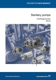
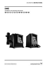
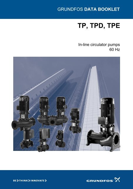
GRUNDFOS DATA BOOKLET<br />
<strong>TP</strong>, <strong>TP</strong>D, <strong>TP</strong>E<br />
In-line circulator pumps<br />
60 Hz
Contents<br />
Pump data<br />
Introduction 4<br />
Type key 5<br />
Performance range<br />
Performance range, 2-pole, PN 6/10/16 6<br />
Performance range, 4-pole, PN 6/10/16 7<br />
Performance range, 2-pole, PN 25 8<br />
Performance range, 4-pole, PN 25 9<br />
Product range<br />
Product range, 2-pole, PN 6/10/16 10<br />
Product range, 4-pole, PN 6/10/16 12<br />
Product range, 2-pole, PN 25 14<br />
Product range, 4-pole, PN 25 15<br />
Operating conditions<br />
Pressure conditions 16<br />
Ambient temperature 16<br />
Pumped liquids<br />
Pumped liquids 17<br />
Liquid temperature 17<br />
List of pumped liquids 18<br />
<strong>TP</strong> Series 200 pumps<br />
Technical data 20<br />
Construction 20<br />
Materials 20<br />
Mechanical shaft seal 21<br />
Connections 21<br />
Features and benefits 21<br />
<strong>TP</strong> Series 300 pumps<br />
Technical data 22<br />
Construction 22<br />
Materials 22<br />
Mechanical shaft seal 22<br />
Connections 23<br />
Features and benefits 23<br />
<strong>TP</strong> Series 400 pumps<br />
Technical data 24<br />
Construction 24<br />
Materials 24<br />
Mechanical shaft seal 25<br />
Connections 25<br />
Features and benefits 25<br />
<strong>TP</strong>E Series 1000 pumps<br />
Technical data 26<br />
Construction 26<br />
Applications 26<br />
Control options 27<br />
Communication<br />
Communication with <strong>TP</strong>E pumps 28<br />
Speed regulation of <strong>TP</strong>E pumps<br />
Affinity equations 29<br />
Motor data<br />
Motor 30<br />
Motor protection 30<br />
Electrical data, standard motors 31<br />
Electrical data, motors with built-in frequency<br />
converter 32<br />
Installation<br />
Mechanical installation 33<br />
Electrical installation 36<br />
Flanges for <strong>TP</strong> pumps<br />
Flange dimensions 38<br />
Curve charts<br />
How to read the curve charts 39<br />
Curve conditions 40<br />
Performance curves/Technical<br />
data<br />
<strong>TP</strong>, <strong>TP</strong>D, <strong>TP</strong>E 2-pole, PN 6/10/16 42<br />
<strong>TP</strong>, <strong>TP</strong>D, <strong>TP</strong>E, 4-pole, PN 6/10/16 58<br />
<strong>TP</strong>, 2-pole, PN 25 84<br />
<strong>TP</strong>, 4-pole, PN 25 86<br />
Weights and shipping volume<br />
<strong>TP</strong>, <strong>TP</strong>D, <strong>TP</strong>E, 2-pole, PN 6/10/16 96<br />
<strong>TP</strong>, <strong>TP</strong>D, <strong>TP</strong>E, 4-pole, PN 6/10/16 97<br />
<strong>TP</strong>, 2-pole, PN 25 98<br />
<strong>TP</strong>, 4-pole, PN 25 99<br />
2
Contents<br />
Accessories<br />
Counter flanges 100<br />
Base plates 103<br />
Blanking flanges 104<br />
Insulating kits 107<br />
Sensors 108<br />
Potentiometer 109<br />
R100 109<br />
G10-LON interface 109<br />
EMC filter 109<br />
Minimum inlet pressure - NPSH<br />
<strong>TP</strong>, <strong>TP</strong>D 2-pole, PN 6/10/16 111<br />
<strong>TP</strong>, <strong>TP</strong>D 4-pole, PN 6/10/16 112<br />
<strong>TP</strong> Series 400, 2-pole, PN 25 112<br />
<strong>TP</strong> Series 400, 4-pole, PN 25 113<br />
Further product documentation<br />
WebCAPS 114<br />
WinCAPS 115<br />
3
Pump data<br />
<strong>TP</strong>, <strong>TP</strong>D, <strong>TP</strong>E<br />
Introduction<br />
<strong>TP</strong> pumps are designed for applications such as<br />
• district heating systems<br />
• heating systems<br />
• air-conditioning systems<br />
• district cooling systems<br />
• water supply<br />
• industrial processes<br />
• industrial cooling.<br />
Most of the pumps are available with either standard<br />
motors (<strong>TP</strong> and <strong>TP</strong>D) or electronically speed-controlled<br />
motors (<strong>TP</strong>E).<br />
The pumps are all single-stage, in-line centrifugal<br />
pumps with standard motor and mechanical shaft seal.<br />
The pumps are of the close-coupled type, i.e. pump and<br />
motor are separate units. Consequently, the pumps are<br />
less sensitive to impurities in the pumped liquid than<br />
similar pumps of the canned rotor type.<br />
<strong>TP</strong> pumps – uncontrolled pumps<br />
The <strong>TP</strong> range is divided into the following four groups<br />
based on their construction: <strong>TP</strong> Series 100, 200, 300<br />
and 400 pumps.<br />
<strong>TP</strong> Series 200 with flange connection<br />
DN 32 to DN 100 and motor sizes from 0.12 to 3 kW.<br />
For further information, see page 20.<br />
<strong>TP</strong> Series 300 with flange connection<br />
DN 32 to DN 200 and motor sizes from 0.55 to 55 kW.<br />
For further information, see page 22.<br />
<strong>TP</strong> Series 400 with flange connection<br />
Grundfos offers two <strong>TP</strong> Series 400 versions:<br />
• 10 bar version with DN 150 to DN 250 flange and<br />
motor sizes from 37 to 132 kW.<br />
• 25 bar version with DN 100 to DN 250 and motor<br />
sizes from 7.5 to 315 kW.<br />
For further information about <strong>TP</strong> Series 400 pumps, see<br />
page 24.<br />
<strong>TP</strong>E pumps – speed-controlled pumps<br />
Based on the construction and choice of material of <strong>TP</strong><br />
pumps, Grundfos offers speed-controlled <strong>TP</strong>E Series<br />
1000 pumps.<br />
<strong>TP</strong>E Series 1000 pumps<br />
The difference between the <strong>TP</strong> and the <strong>TP</strong>E Series<br />
1000 pump range is the motor. The motors of <strong>TP</strong>E<br />
Series 1000 pumps have built-in frequency converter.<br />
Via an external signal (from a sensor or a controller),<br />
<strong>TP</strong>E Series 1000 pumps allow for any configuration and<br />
control method required: Constant pressure, constant<br />
temperature or constant flow.<br />
Note: <strong>TP</strong>E Series 1000 pumps are delivered without a<br />
differential-pressure sensor.<br />
<strong>TP</strong>E Series 1000 pumps are based on <strong>TP</strong> Series 200<br />
and 300 pumps. The pump materials are the same as<br />
those of the <strong>TP</strong> pump range.<br />
For further information, see page 26.<br />
Why select a <strong>TP</strong>E pump?<br />
A <strong>TP</strong>E pump with electronic, speed-controlled adaptation<br />
of performance offers these obvious benefits:<br />
• energy savings<br />
• increased comfort<br />
• control and monitoring of the pump performance<br />
• communication with the pump.<br />
ATEX-approved <strong>TP</strong> pumps<br />
On request, Grundfos offers <strong>TP</strong> and <strong>TP</strong>D pumps with<br />
ATEX-approval.<br />
All ATEX-approved <strong>TP</strong> pumps are in accordance with<br />
Council directive 94/9/EC (Group II, category 3).<br />
High-efficiency motors<br />
<strong>TP</strong> pumps are fitted with high-efficiency motors.<br />
2- and 4-pole <strong>TP</strong> pumps with motor sizes from 1.1 to<br />
90 kW are fitted with high-efficiency motors (EFF1).<br />
EFF1 is the highest efficiency class defined by CEMEP.<br />
4
Pump data<br />
<strong>TP</strong>, <strong>TP</strong>D, <strong>TP</strong>E<br />
Type key<br />
Example <strong>TP</strong> E D 65 -120 /2 -A -F -A -AUUE<br />
Pump range<br />
Electronically speed controlled pump Series 1000<br />
Twin-head pump<br />
Nominal diameter of suction and discharge ports (DN)<br />
Maximum head [dm]<br />
Pole number<br />
Code for pump version:<br />
A = Basic version<br />
I = PN 6 flange<br />
X = Special version<br />
Code for pipework connection:<br />
F = DIN flange<br />
O = Union<br />
Code for materials:<br />
A = Basic version<br />
Z = Bronze pump housing and motor stool<br />
B = Bronze impeller<br />
Code for shaft seal<br />
(incl. other plastic and rubber components in the pump except the neck ring)<br />
Codes for shaft seal<br />
Example B B U E<br />
Grundfos type designation<br />
A = O-ring seal with fixed seal driver<br />
B = Rubber bellows seal<br />
D = O-ring seal, balanced<br />
G = Bellows seal with reduced seal faces<br />
R = O-ring seal with reduced seal faces<br />
Material of rotating face<br />
A = Carbon, antimony-impregnated<br />
B = Carbon, synthetic resin-impregnated<br />
Q = Silicon carbide<br />
U = Tungsten carbide<br />
Material of stationary seat<br />
B = Carbon, synthetic resin-impregnated<br />
Q = Silicon carbide<br />
U = Tungsten carbide<br />
Material of secondary seal<br />
E = EPDM<br />
P = NBR rubber<br />
V = FKM<br />
5
Performance range<br />
<strong>TP</strong>, <strong>TP</strong>D, <strong>TP</strong>E<br />
2-pole, PN 6/10/16<br />
Performance range, 2-pole, PN 6/10/16<br />
(See page 42 for performance curves)<br />
p<br />
[kPa]<br />
H<br />
[m]<br />
1000<br />
900<br />
800<br />
700<br />
600<br />
500<br />
100<br />
80<br />
60<br />
50<br />
400<br />
40<br />
300<br />
30<br />
200<br />
20<br />
15<br />
100<br />
90<br />
80<br />
70<br />
60<br />
50<br />
10<br />
8<br />
6<br />
5<br />
40<br />
4<br />
30<br />
3<br />
TM02 5101 1804<br />
<strong>TP</strong>(D), <strong>TP</strong>E<br />
PN 6-16, 2-pole, 60 Hz<br />
50-1050<br />
65-1050<br />
50-880<br />
40-930<br />
32-820<br />
80-750<br />
100-230<br />
80-640<br />
80-530<br />
80-480<br />
65-260<br />
65-540<br />
80-200<br />
80-290<br />
80-240<br />
65-910<br />
50-790<br />
65-740<br />
50-720<br />
32-680<br />
80-400<br />
65-480<br />
65-630<br />
50-440<br />
65-390<br />
50-410<br />
80-330<br />
50-350<br />
65-340<br />
50-250<br />
40-450<br />
40-740<br />
40-550<br />
50-300<br />
40-850<br />
100-700<br />
32-550<br />
32-450<br />
50-540<br />
40-390<br />
40-370<br />
32-360<br />
32-330<br />
32-300<br />
65-220<br />
32-260<br />
32-220<br />
32-160<br />
40-330<br />
40-240<br />
40-270<br />
40-160<br />
50-240<br />
65-240<br />
100-300<br />
100-350<br />
100-370<br />
100-630<br />
100-530<br />
100-380<br />
50-160<br />
65-160<br />
80-160<br />
32-80<br />
40-80<br />
50-80<br />
65-80<br />
4 5 6 8 10 12 15 20 30 40 50 60 80 100 120 150 200 300<br />
Q [m³/h]<br />
2 3 4 5 6 7 8 9 10 20 30 40 50 60 Q [l/s]<br />
Note: All QH curves apply to single-head pumps. For further information about curve conditions, see page 40.<br />
The hatched area shows the performance range of <strong>TP</strong>E pumps.<br />
6
Performance range<br />
<strong>TP</strong>, <strong>TP</strong>D, <strong>TP</strong>E<br />
4-pole, PN 6/10/16<br />
Performance range, 4-pole, PN 6/10/16<br />
(See page 58 for performance curves)<br />
p<br />
[kPa]<br />
700<br />
600<br />
500<br />
H<br />
[m]<br />
60<br />
50<br />
400<br />
40<br />
300<br />
30<br />
200<br />
20<br />
15<br />
100<br />
10<br />
80<br />
8<br />
60<br />
50<br />
6<br />
5<br />
40<br />
4<br />
30<br />
3<br />
20<br />
2<br />
TM02 8931 1305<br />
<strong>TP</strong>(D), <strong>TP</strong>E<br />
PN 6-16, 4-pole, 60 Hz<br />
125-490<br />
100-470<br />
150-400<br />
80-510<br />
150-550<br />
125-430<br />
100-390<br />
65-330<br />
125-210<br />
150-180<br />
125-160<br />
125-360<br />
100-340<br />
125-320<br />
100-290<br />
125-260<br />
100-240<br />
80-460<br />
80-410<br />
50-340<br />
50-270<br />
40-220<br />
50-240<br />
65-230<br />
80-340<br />
80-280<br />
65-310<br />
32-190<br />
150-210<br />
100-200<br />
100-170<br />
50-190<br />
65-190<br />
50-140<br />
65-150<br />
100-130<br />
80-230<br />
80-170<br />
80-150<br />
40-160<br />
40-190<br />
32-140<br />
150-490<br />
250-580<br />
200-570<br />
200-430<br />
150-420<br />
200-520<br />
150-360<br />
150-380<br />
250-530<br />
200-380<br />
250-450<br />
200-330<br />
200-290<br />
150-300<br />
200-270<br />
150-240<br />
200-350<br />
200-320<br />
200-280<br />
65-130<br />
32-120<br />
50-120<br />
80-110<br />
125-130<br />
40-120<br />
50-110<br />
100-100<br />
40-80<br />
50-80<br />
65-80<br />
80-80 100-80<br />
32-80<br />
32-40<br />
50-40<br />
65-40<br />
80-40 100-40<br />
40-40<br />
4 6 8 10 15 20 30 40 60 80 100 150 200 300 400 600 800 1000 1500<br />
Q [m³/h]<br />
2 3 4 5 6 8 10 20 30 40 50 60 80 100 200 Q [l/s]<br />
Note: All QH curves apply to single-head pumps. For further information about curve conditions, see page 40.<br />
The hatched area shows the performance range of <strong>TP</strong>E pumps.<br />
7
Performance range<br />
<strong>TP</strong><br />
2-pole, PN 25<br />
Performance range, 2-pole, PN 25<br />
(See page 84 for performance curves)<br />
p<br />
[kPa]<br />
H<br />
[m]<br />
3000<br />
300<br />
2000<br />
200<br />
150<br />
1000<br />
900<br />
800<br />
100<br />
90<br />
80<br />
700<br />
70<br />
600<br />
60<br />
500<br />
50<br />
400<br />
40<br />
TM02 6870 0805<br />
<strong>TP</strong><br />
PN 25, 2-pole, 60 Hz<br />
100-2350<br />
100-2100<br />
100-1700<br />
100-1560<br />
100-1450<br />
100-1250<br />
100-1350<br />
100-1100<br />
100-1000<br />
25 30 40 50 60 80 100 150 200 300 400 500<br />
Q [m³/h]<br />
7 8 9 10 20 30 40 50 60 70 80 90 100 Q [l/s]<br />
8
Performance range<br />
<strong>TP</strong><br />
4-pole, PN 25<br />
Performance range, 4-pole, PN 25<br />
(See page 86 for performance curves)<br />
p<br />
[kPa]<br />
H<br />
[m]<br />
1000<br />
900<br />
800<br />
700<br />
100<br />
90<br />
80<br />
70<br />
600<br />
60<br />
500<br />
50<br />
400<br />
40<br />
300<br />
30<br />
200<br />
20<br />
15<br />
100<br />
10<br />
TM02 7003 0805<br />
<strong>TP</strong><br />
PN 25, 4-pole, 60 Hz<br />
250-1020<br />
150-930<br />
200-930<br />
200-840<br />
250-910<br />
150-800<br />
150-710<br />
250-800<br />
200-760<br />
100-590<br />
250-720<br />
200-670<br />
125-620<br />
125-570<br />
200-560<br />
250-550<br />
200-520<br />
150-490<br />
125-500<br />
250-500<br />
150-450<br />
125-440<br />
150-370<br />
125-370<br />
125-350<br />
125-310<br />
100-530<br />
100-450<br />
100-420<br />
100-360<br />
100-330<br />
100-250<br />
150-330<br />
250-430<br />
200-370<br />
125-270<br />
100-210<br />
125-240<br />
200-350<br />
20 30 40 50 60 80 100 150 200 300 400 500 600 800 1000 1500<br />
Q [m³/h]<br />
6 7 8 9 10 20 30 40 50 60 70 80 100 200 300 Q [l/s]<br />
9
Product range<br />
<strong>TP</strong>, <strong>TP</strong>D, <strong>TP</strong>E<br />
Product range, 2-pole, PN 6/10/16<br />
Pump type<br />
Design Shaft seal Pressure stage Materials Standard motor<br />
<strong>TP</strong>E Series 1000 (1<br />
<strong>TP</strong> Series 200<br />
<strong>TP</strong> Series 300<br />
<strong>TP</strong> Series 400<br />
BUBE<br />
AUUE<br />
RUUE<br />
BAQE<br />
BQQE<br />
GQQE<br />
DBUE<br />
PN 6/10 combination flange<br />
PN 10<br />
PN 16<br />
PN 25<br />
Electronically speed<br />
controlled motor<br />
Pump housing Impeller Voltage [V] Voltage [V]<br />
Cast iron<br />
EN-GJL-250<br />
Nodular cast iron<br />
EN-GJS-400-18<br />
Bronze<br />
Stainless steel<br />
Cast iron<br />
Nodular cast iron<br />
EN-GJS-400-15<br />
Bronze<br />
<strong>TP</strong> 32-80/2 • • • • • • • • 0.37<br />
<strong>TP</strong> 32-160/2 • • • • • • • • 0.55<br />
<strong>TP</strong> 32-220/2 • • • • • • • • 0.75<br />
3 x 220-255 ΔV/<br />
3 x 380-440 YV<br />
P 2<br />
[kW]<br />
<strong>TP</strong> 32-260/2 • • • • • • • • 1.1<br />
<strong>TP</strong> 32-330/2 • • • • • • • • 1.5<br />
<strong>TP</strong>, <strong>TP</strong>D 32-300/2 • • • • • • • • • 2.2 2.2 2.2<br />
<strong>TP</strong>, <strong>TP</strong>D 32-360/2 • • • • • • • • • 3.0 3.0 3.0<br />
<strong>TP</strong>, <strong>TP</strong>D 32-450/2 • • • • • • • • • 4.0 4.0 4.0<br />
<strong>TP</strong>, <strong>TP</strong>D 32-550/2 • • • • • • • • • 5.5 5.5 5.5<br />
<strong>TP</strong>, <strong>TP</strong>D 32-680/2 • • • • • • • • • 7.5 7.5 7.5<br />
<strong>TP</strong>, <strong>TP</strong>D 32-820/2 • • • • • • • • • 11.0 11.0 11.0<br />
<strong>TP</strong> 40-80/2 • • • • • • • • 0.55<br />
<strong>TP</strong> 40-160/2 • • • • • • • • 0.75<br />
<strong>TP</strong> 40-240/2 • • • • • • • • 1.1<br />
<strong>TP</strong> 40-270/2 • • • • • • • • 1.5<br />
<strong>TP</strong> 40-330/2 • • • • • • • • 2.2<br />
<strong>TP</strong> 40-390/2 • • • • • • • • 3.0<br />
<strong>TP</strong>, <strong>TP</strong>D 40-370/2 • • • • • • • • • 4.0 4.0 4.0<br />
<strong>TP</strong>, <strong>TP</strong>D 40-450/2 • • • • • • • • • 5.5 5.5 5.5<br />
<strong>TP</strong>, <strong>TP</strong>D 40-550/2 • • • • • • • • • 7.5 7.5 7.5<br />
<strong>TP</strong>, <strong>TP</strong>D 40-740/2 • • • • • • • • • 11.0 11.0 11.0<br />
<strong>TP</strong>, <strong>TP</strong>D 40-850/2 • • • • • • • • • 15.0 15.0 15.0<br />
<strong>TP</strong>, <strong>TP</strong>D 40-930/2 • • • • • • • • • 18.5 18.5 18.5<br />
<strong>TP</strong> 50-80/2 • • • • • • • • 0.55<br />
<strong>TP</strong> 50-160/2 • • • • • • • • 1.1<br />
<strong>TP</strong> 50-240/2 • • • • • • • • 1.5<br />
<strong>TP</strong>, <strong>TP</strong>D 50-250/2 • • • • • • • • • 2.2 2.2 2.2<br />
<strong>TP</strong>, <strong>TP</strong>D 50-300/2 • • • • • • • • • 3.0 3.0 3.0<br />
<strong>TP</strong>, <strong>TP</strong>D 50-350/2 • • • • • • • • • 4.0 4.0 4.0<br />
<strong>TP</strong>, <strong>TP</strong>D 50-410/2 • • • • • • • • • 5.5 5.5 5.5<br />
<strong>TP</strong>, <strong>TP</strong>D 50-440/2 • • • • • • • • • 7.5 7.5 7.5<br />
<strong>TP</strong>, <strong>TP</strong>D 50-540/2 • • • • • • • • • 11.0 11.0 11.0<br />
<strong>TP</strong>, <strong>TP</strong>D 50-720/2 • • • • • • • • • 15.0 15.0 15.0<br />
<strong>TP</strong>, <strong>TP</strong>D 50-790/2 • • • • • • • • • 18.5 18.5 18.5<br />
<strong>TP</strong>, <strong>TP</strong>D 50-880/2 • • • • • • • • • 22.0 22.0 22.0<br />
<strong>TP</strong>, <strong>TP</strong>D 50-1050/2 • • • • • • • • 30.0 30.0<br />
<strong>TP</strong> 65-80/2 • • • • • • • • 1.1<br />
<strong>TP</strong> 65-160/2 • • • • • • • • 1.5<br />
<strong>TP</strong> 65-240/2 • • • • • • • • 2.2<br />
<strong>TP</strong>, <strong>TP</strong>D 65-220/2 • • • • • • • • • 3.0 3.0 3.0<br />
<strong>TP</strong>, <strong>TP</strong>D 65-260/2 • • • • • • • • • 4.0 4.0 4.0<br />
<strong>TP</strong>, <strong>TP</strong>D 65-340/2 • • • • • • • • • 5.5 5.5 5.5<br />
<strong>TP</strong>, <strong>TP</strong>D 65-390/2 • • • • • • • • • 7.5 7.5 7.5<br />
<strong>TP</strong>, <strong>TP</strong>D 65-480/2 • • • • • • • • • 11.0 11.0 11.0<br />
<strong>TP</strong>, <strong>TP</strong>D 65-540/2 • • • • • • • • • 15.0 15.0 15.0<br />
<strong>TP</strong>, <strong>TP</strong>D 65-630/2 • • • • • • • • • 18.5 18.5 18.5<br />
<strong>TP</strong>, <strong>TP</strong>D 65-740/2 • • • • • • • • • 22.0 22.0 22.0<br />
<strong>TP</strong>, <strong>TP</strong>D 65-910/2 • • • • • • • • 30.0 30.0<br />
3 x 220-277 ΔV/<br />
3 x 380-480 YV<br />
P 2<br />
[kW]<br />
3 x 380-480 ΔV<br />
P 2<br />
[kW]<br />
3 x 380-480 ΔV/<br />
3 x 660-690 YV (2<br />
P 2<br />
[kW]<br />
3 x 380-415 V<br />
P 2<br />
[kW]<br />
3 x 380-480 V<br />
P 2<br />
[kW]<br />
10
Product range<br />
<strong>TP</strong>, <strong>TP</strong>D, <strong>TP</strong>E<br />
Pump type<br />
<strong>TP</strong>, <strong>TP</strong>D 65-1050/2 • • • • • • • • 37.0 37.0<br />
<strong>TP</strong> 80-160/2 • • • • • • • • 3.0<br />
<strong>TP</strong>, <strong>TP</strong>D 80-200/2 • • • • • • • • • 4.0 4.0 4.0<br />
<strong>TP</strong>, <strong>TP</strong>D 80-240/2 • • • • • • • • • 5.5 5.5 5.5<br />
<strong>TP</strong>, <strong>TP</strong>D 80-290/2 • • • • • • • • • 7.5 7.5 7.5<br />
<strong>TP</strong>, <strong>TP</strong>D 80-330/2 • • • • • • • • • 11.0 11.0 11.0<br />
<strong>TP</strong>, <strong>TP</strong>D 80-400/2 • • • • • • • • • 15.0 15.0 15.0<br />
<strong>TP</strong>, <strong>TP</strong>D 80-480/2 • • • • • • • • • 18.5 18.5 18.5<br />
<strong>TP</strong>, <strong>TP</strong>D 80-530/2 • • • • • • • • • 22.0 22.0 22.0<br />
<strong>TP</strong>, <strong>TP</strong>D 80-640/2 • • • • • • • • 30.0 30.0<br />
<strong>TP</strong>, <strong>TP</strong>D 80-750/2 • • • • • • • • 37.0 37.0<br />
<strong>TP</strong>, <strong>TP</strong>D 100-230/2 • • • • • • • • • 7.5 7.5 7.5<br />
<strong>TP</strong>, <strong>TP</strong>D 100-300/2 • • • • • • • • • 11.0 11.0 11.0<br />
<strong>TP</strong>, <strong>TP</strong>D 100-370/2 • • • • • • • • • 15.0 15.0 15.0<br />
<strong>TP</strong>, <strong>TP</strong>D 100-350/2 • • • • • • • • • 18.5 18.5 18.5<br />
<strong>TP</strong>, <strong>TP</strong>D 100-380/2 • • • • • • • • • 22.0 22.0 22.0<br />
<strong>TP</strong>, <strong>TP</strong>D 100-530/2 • • • • • • • • 30.0 30.0<br />
<strong>TP</strong>, <strong>TP</strong>D 100-630/2 • • • • • • • • 37.0 37.0<br />
<strong>TP</strong>, <strong>TP</strong>D 100-700/2 • • • • • • • • 45.0 45.0<br />
• Standard<br />
Design Shaft seal Pressure stage Materials Standard motor<br />
<strong>TP</strong>E Series 1000 (1<br />
<strong>TP</strong> Series 200<br />
<strong>TP</strong> Series 300<br />
<strong>TP</strong> Series 400<br />
BUBE<br />
AUUE<br />
RUUE<br />
BAQE<br />
BQQE<br />
GQQE<br />
DBUE<br />
PN 6/10 combination flange<br />
PN 10<br />
PN 16<br />
PN 25<br />
1 <strong>TP</strong>E pumps are not available in twin-head versions.<br />
2 2-pole motors above 7.5 kW can be operated at 3 x 660-690 YV. Smaller motor sizes cannot.<br />
Electronically speed<br />
controlled motor<br />
Pump housing Impeller Voltage [V] Voltage [V]<br />
Cast iron<br />
EN-GJL-250<br />
Nodular cast iron<br />
EN-GJS-400-18<br />
Bronze<br />
Stainless steel<br />
Cast iron<br />
Nodular cast iron<br />
EN-GJS-400-15<br />
Bronze<br />
3 x 220-255 ΔV/<br />
3 x 380-440 YV<br />
P 2<br />
[kW]<br />
3 x 220-277 ΔV/<br />
3 x 380-480 YV<br />
P 2<br />
[kW]<br />
3 x 380-480 ΔV<br />
P 2<br />
[kW]<br />
3 x 380-480 ΔV/<br />
3 x 660-690 YV (2<br />
P 2<br />
[kW]<br />
3 x 380-415 V<br />
P 2<br />
[kW]<br />
3 x 380-480 V<br />
P 2<br />
[kW]<br />
11
Product range<br />
<strong>TP</strong>, <strong>TP</strong>D, <strong>TP</strong>E<br />
Product range, 4-pole, PN 6/10/16<br />
Pump type<br />
Design Shaft seal Pressure stage Materials Standard motor<br />
<strong>TP</strong>E Series 1000 (1<br />
<strong>TP</strong> Series 200<br />
<strong>TP</strong> Series 300<br />
<strong>TP</strong> Series 400<br />
BUBE<br />
AUUE<br />
RUUE<br />
BAQE<br />
BQQE<br />
GQQE<br />
DBUE<br />
PN 6/10 combination flange<br />
PN 10<br />
PN 16<br />
PN 25<br />
Electronically<br />
speed controlled<br />
motor<br />
Pump housing Impeller Voltage [V] Voltage [V]<br />
Cast iron<br />
EN-GJL-250<br />
Nodular cast iron<br />
EN-GJS-400-18<br />
Bronze<br />
Stainless steel<br />
Cast iron<br />
<strong>TP</strong> 32-40/4 • • • • • • • • 0.12<br />
<strong>TP</strong> 32-80/4 • • • • • • • • 0.25<br />
<strong>TP</strong>, <strong>TP</strong>D 32-120/4 • • • • • • • • 0.55<br />
<strong>TP</strong>, <strong>TP</strong>D 32-140/4 • • • • • • • • 0.75<br />
<strong>TP</strong>, <strong>TP</strong>D 32-190/4 • • • • • • • • • 1.1 1.1<br />
<strong>TP</strong> 40-40/4 • • • • • • • • 0.25<br />
<strong>TP</strong> 40-80/4 • • • • • • • • 0.55<br />
<strong>TP</strong>, <strong>TP</strong>D 40-120/4 • • • • • • • • 0.75<br />
<strong>TP</strong>, <strong>TP</strong>D 40-160/4 • • • • • • • • • 1.1 1.1<br />
<strong>TP</strong>, <strong>TP</strong>D 40-190/4 • • • • • • • • • 1.5 1.5<br />
<strong>TP</strong>, <strong>TP</strong>D 40-220/4 • • • • • • • • • 2.2 2.2 2.2<br />
<strong>TP</strong> 50-40/4 • • • • • • • • 0.25<br />
<strong>TP</strong> 50-80/4 • • • • • • • • 0.55<br />
<strong>TP</strong>, <strong>TP</strong>D 50-110/4 • • • • • • • • 0.75<br />
<strong>TP</strong>, <strong>TP</strong>D 50-120/4 • • • • • • • • • 1.1 1.1<br />
<strong>TP</strong>, <strong>TP</strong>D 50-140/4 • • • • • • • • • 1.5 1.5<br />
<strong>TP</strong>, <strong>TP</strong>D 50-190/4 • • • • • • • • • 2.2 2.2 2.2<br />
<strong>TP</strong>, <strong>TP</strong>D 50-240/4 • • • • • • • • • 3.0 3.0 3.0<br />
<strong>TP</strong>, <strong>TP</strong>D 50-270/4 • • • • • • • • • 4.0 4.0 4.0<br />
<strong>TP</strong>, <strong>TP</strong>D 50-340/4 • • • • • • • • • 5.5 5.5 5.5<br />
<strong>TP</strong> 65-40/4 • • • • • • • • 0.37<br />
Nodular cast iron<br />
EN-GJS-400-15<br />
Bronze<br />
3 x 220-255 ΔV/<br />
3 x 380-440 YV<br />
P 2<br />
[kW]<br />
<strong>TP</strong> 65-80/4 • • • • • • • • 1.1<br />
<strong>TP</strong>, <strong>TP</strong>D 65-130/4 • • • • • • • • • 1.5 1.5<br />
<strong>TP</strong>, <strong>TP</strong>D 65-150/4 • • • • • • • • • 2.2 2.2 2.2<br />
<strong>TP</strong>, <strong>TP</strong>D 65-190/4 • • • • • • • • • 3.0 3.0 3.0<br />
<strong>TP</strong>, <strong>TP</strong>D 65-230/4 • • • • • • • • • 4.0 4.0 4.0<br />
<strong>TP</strong>, <strong>TP</strong>D 65-310/4 • • • • • • • • • 5.5 5.5 5.5<br />
<strong>TP</strong>, <strong>TP</strong>D 65-330/4 • • • • • • • • • 7.5 7.5 7.5<br />
<strong>TP</strong> 80-40/4 • • • • • • • • 0.75<br />
<strong>TP</strong> 80-80/4 • • • • • • • • 1.5 1.5<br />
<strong>TP</strong>, <strong>TP</strong>D 80-110/4 • • • • • • • • • 2.2 2.2 2.2<br />
<strong>TP</strong>, <strong>TP</strong>D 80-150/4 • • • • • • • • • 3.0 3.0 3.0<br />
<strong>TP</strong>, <strong>TP</strong>D 80-170/4 • • • • • • • • • 4.0 4.0 4.0<br />
<strong>TP</strong>, <strong>TP</strong>D 80-230/4 • • • • • • • • • 5.5 5.5 5.5<br />
<strong>TP</strong>, <strong>TP</strong>D 80-280/4 • • • • • • • • • 7.5 7.5 7.5<br />
<strong>TP</strong>, <strong>TP</strong>D 80-340/4 • • • • • • • • • 11.0 11.0 11.0<br />
<strong>TP</strong>, <strong>TP</strong>D 80-410/4 • • • • • • • • • 15.0 15.0 15.0<br />
<strong>TP</strong>, <strong>TP</strong>D 80-460/4 • • • • • • • • • 18.5 18.5 18.5<br />
<strong>TP</strong>, <strong>TP</strong>D 80-510/4 • • • • • • • • • 22.0 22.0 22.0<br />
<strong>TP</strong> 100-40/4 • • • • • • • • 1.1 1.1<br />
<strong>TP</strong> 100-80/4 • • • • • • • • 2.2 2.2<br />
<strong>TP</strong>, <strong>TP</strong>D 100-100/4 • • • • • • • • • 3.0 3.0 3.0<br />
<strong>TP</strong>, <strong>TP</strong>D 100-130/4 • • • • • • • • • 4.0 4.0 4.0<br />
<strong>TP</strong>, <strong>TP</strong>D 100-170/4 • • • • • • • • • 5.5 5.5 5.5<br />
<strong>TP</strong>, <strong>TP</strong>D 100-200/4 • • • • • • • • • 7.5 7.5 7.5<br />
<strong>TP</strong>, <strong>TP</strong>D 100-240/4 • • • • • • • • • 11.0 11.0 11.0<br />
<strong>TP</strong>, <strong>TP</strong>D 100-290/4 • • • • • • • • • 15.0 15.0 15.0<br />
<strong>TP</strong>, <strong>TP</strong>D 100-340/4 • • • • • • • • • 18.5 18.5 18.5<br />
3 x 220-277 ΔV/<br />
3 x 380-480 YV<br />
P 2<br />
[kW]<br />
3 x 380-480 ΔV<br />
P 2<br />
[kW]<br />
3 x 380-480 ΔV/<br />
3 x 660-690 YV(2<br />
P 2<br />
[kW]<br />
3 x 380-415 V<br />
P 2<br />
[kW]<br />
3 x 380-480 V<br />
P 2<br />
[kW]<br />
12
Product range<br />
<strong>TP</strong>, <strong>TP</strong>D, <strong>TP</strong>E<br />
Pump type<br />
<strong>TP</strong>, <strong>TP</strong>D 100-390/4 • • • • • • • • • 22.0 22.0 22.0<br />
<strong>TP</strong>, <strong>TP</strong>D 100-470/4 • • • • • • • • 30.0 30.0<br />
<strong>TP</strong>, <strong>TP</strong>D 125-130/4 • • • • • • • • • 5.5 5.5 5.5<br />
<strong>TP</strong>, <strong>TP</strong>D 125-160/4 • • • • • • • • • 7.5 7.5 7.5<br />
<strong>TP</strong>, <strong>TP</strong>D 125-210/4 • • • • • • • • • 11.0 11.0 11.0<br />
<strong>TP</strong>, <strong>TP</strong>D 125-260/4 • • • • • • • • • 15.0 15.0 15.0<br />
<strong>TP</strong>, <strong>TP</strong>D 125-320/4 • • • • • • • • • 18.5 18.5 18.5<br />
<strong>TP</strong>, <strong>TP</strong>D 125-360/4 • • • • • • • • • 22.0 22.0 22.0<br />
<strong>TP</strong>, <strong>TP</strong>D 125-430/4 • • • • • • • • 30.0 30.0<br />
<strong>TP</strong>, <strong>TP</strong>D 125-490/4 • • • • • • • • 37.0 37.0<br />
<strong>TP</strong>, <strong>TP</strong>D 150-180/4 • • • • • • • • • 15.0 15.0 15.0<br />
<strong>TP</strong>, <strong>TP</strong>D 150-210/4 • • • • • • • • • 18.5 18.5 18.5<br />
<strong>TP</strong>, <strong>TP</strong>D 150-240/4 • • • • • • • • • 22.0 22.0 22.0<br />
<strong>TP</strong>, <strong>TP</strong>D 150-300/4 • • • • • • • • 30.0<br />
<strong>TP</strong> 150-360/4 • • • • • • • 30.0<br />
<strong>TP</strong> 150-380/4 • • • • • • • • 37.0<br />
<strong>TP</strong> 150-400/4 • • • • • • • 37.0<br />
<strong>TP</strong> 150-420/4 • • • • • • • • 45.0<br />
<strong>TP</strong> 150-490/4 • • • • • • • • 55.0<br />
<strong>TP</strong> 150-550/4 • • • • • • • • 75.0<br />
<strong>TP</strong> 200-270/4 • • • • • • • 37.0<br />
<strong>TP</strong> 200-280/4 • • • • • • • • 30.0<br />
<strong>TP</strong> 200-290/4 • • • • • • • 45.0<br />
<strong>TP</strong> 200-320/4 • • • • • • • • 37.0<br />
<strong>TP</strong> 200-330/4 • • • • • • • 55.0<br />
<strong>TP</strong> 200-350/4 • • • • • • • • 45.0<br />
<strong>TP</strong> 200-380/4 • • • • • • • • 55.0<br />
<strong>TP</strong> 200-430/4 • • • • • • • 55.0<br />
<strong>TP</strong> 200-520/4 • • • • • • • • 75.0<br />
<strong>TP</strong> 200-570/4 • • • • • • • • 90.0<br />
<strong>TP</strong> 250-450/4 • • • • • • • • 90.0<br />
<strong>TP</strong> 250-530/4 • • • • • • • • 110.0<br />
<strong>TP</strong> 250-580/4 • • • • • • • • 132.0<br />
• Standard<br />
Design Shaft seal Pressure stage Materials Standard motor<br />
<strong>TP</strong>E Series 1000 (1<br />
<strong>TP</strong> Series 200<br />
<strong>TP</strong> Series 300<br />
<strong>TP</strong> Series 400<br />
BUBE<br />
AUUE<br />
RUUE<br />
BAQE<br />
BQQE<br />
GQQE<br />
DBUE<br />
PN 6/10 combination flange<br />
PN 10<br />
PN 16<br />
PN 25<br />
1 <strong>TP</strong>E pumps are not available in twin-head versions.<br />
2 4-pole motors above 4 kW can be operated at 3 x 660-690 YV. Smaller motor sizes cannot.<br />
Electronically<br />
speed controlled<br />
motor<br />
Pump housing Impeller Voltage [V] Voltage [V]<br />
Cast iron<br />
EN-GJL-250<br />
Nodular cast iron<br />
EN-GJS-400-18<br />
Bronze<br />
Stainless steel<br />
Cast iron<br />
Nodular cast iron<br />
EN-GJS-400-15<br />
Bronze<br />
3 x 220-255 ΔV/<br />
3 x 380-440 YV<br />
P 2<br />
[kW]<br />
3 x 220-277 ΔV/<br />
3 x 380-480 YV<br />
P 2<br />
[kW]<br />
3 x 380-480 ΔV<br />
P 2<br />
[kW]<br />
3 x 380-480 ΔV/<br />
3 x 660-690 YV(2<br />
P 2<br />
[kW]<br />
3 x 380-415 V<br />
P 2<br />
[kW]<br />
3 x 380-480 V<br />
P 2<br />
[kW]<br />
13
Product range<br />
<strong>TP</strong>, <strong>TP</strong>D, <strong>TP</strong>E<br />
Product range, 2-pole, PN 25<br />
Pump type<br />
• Standard<br />
Electronically speed<br />
Design Shaft seal Pressure stage Materials Standard motor<br />
controlled motor<br />
Pump housing Impeller Voltage [V] Voltage [V]<br />
<strong>TP</strong>E Series 1000 (1<br />
<strong>TP</strong> Series 200<br />
<strong>TP</strong> Series 300<br />
<strong>TP</strong> Series 400<br />
BUBE<br />
AUUE<br />
RUUE<br />
BAQE<br />
BQQE<br />
GQQE<br />
DBUE<br />
PN 6/10 combination flange<br />
PN 10<br />
PN 16<br />
PN 25<br />
Cast iron<br />
EN-GJL-250<br />
Nodular cast iron<br />
EN-GJS-400-18<br />
Bronze<br />
Stainless steel<br />
Cast iron<br />
Nodular cast iron<br />
EN- GJS-400-15<br />
Bronze<br />
<strong>TP</strong> 100-1000/2 • • • • • • 75.0<br />
<strong>TP</strong> 100-1100/2 • • • • • • 90.0<br />
<strong>TP</strong> 100-1250/2 • • • • • • 110.0<br />
<strong>TP</strong> 100-1350/2 • • • • • • 132.0<br />
<strong>TP</strong> 100-1450/2 • • • • • • 110.0<br />
<strong>TP</strong> 100-1560/2 • • • • • • 132.0<br />
<strong>TP</strong> 100-1700/2 • • • • • • 160.0<br />
<strong>TP</strong> 100-2100/2 • • • • • • 20.00<br />
<strong>TP</strong> 100-2350/2 • • • • • • 250.0<br />
3 x 220-255 ΔV/<br />
3 x 380-440 YV<br />
P 2<br />
[kW]<br />
3 x 220-277 ΔV/<br />
3 x 380-480 YV<br />
P 2<br />
[kW]<br />
3 x 380-480 ΔV<br />
P 2<br />
[kW]<br />
3 x 380-480 ΔV/<br />
3 x 660-690 YV<br />
P 2<br />
[kW]<br />
3 x 380-415 V<br />
P 2<br />
[kW]<br />
3 x 380-480 V<br />
P 2<br />
[kW]<br />
14
Product range<br />
<strong>TP</strong>, <strong>TP</strong>D, <strong>TP</strong>E<br />
Product range, 4-pole, PN 25<br />
Pump type<br />
• Standard<br />
Design Shaft seal Pressure stage Materials Standard motor<br />
T<strong>TP</strong>E Series 1000 (1<br />
<strong>TP</strong> Series 200<br />
<strong>TP</strong> Series 300<br />
<strong>TP</strong> Series 400<br />
BUBE<br />
AUUE<br />
RUUE<br />
BAQE<br />
BQQE<br />
GQQE<br />
DBUE<br />
PN 6/10 combination flange<br />
PN 10<br />
PN 16<br />
PN 25<br />
Electronically speed<br />
controlled motor<br />
Pump housing Impeller Voltage [V] Voltage [V]<br />
Cast iron<br />
EN-GJL-250<br />
Nodular cast iron<br />
EN-GJS-400-18<br />
Bronze<br />
Stainless steel<br />
Cast iron<br />
<strong>TP</strong> 100-210/4 • • • • • • 7.5<br />
<strong>TP</strong> 100-250/4 • • • • • • 11.0<br />
<strong>TP</strong> 100-330/4 • • • • • • 15.0<br />
<strong>TP</strong> 100-360/4 • • • • • • 18.5<br />
<strong>TP</strong> 100-420/4 • • • • • • 18.5<br />
<strong>TP</strong> 100-450/4 • • • • • • 22.0<br />
<strong>TP</strong> 100-530/4 • • • • • • 30.0<br />
<strong>TP</strong> 100-590/4 • • • • • • 37.0<br />
<strong>TP</strong> 125-240/4 • • • • • • 15.0<br />
<strong>TP</strong> 125-270/4 • • • • • • 18.5<br />
<strong>TP</strong> 125-310/4 • • • • • • 22.0<br />
<strong>TP</strong> 125-370/4 • • • • • • 30.0<br />
<strong>TP</strong> 125-350/4 • • • • • • 22.0<br />
<strong>TP</strong> 125-440/4 • • • • • • 30.0<br />
<strong>TP</strong> 125-500/4 • • • • • • 37.0<br />
<strong>TP</strong> 125-570/4 • • • • • • 45.0<br />
<strong>TP</strong> 125-620/4 • • • • • • 55.0<br />
<strong>TP</strong> 150-330/4 • • • • • • 30.0<br />
<strong>TP</strong> 150-370/4 • • • • • • 37.0<br />
<strong>TP</strong> 150-450/4 • • • • • • 45.0<br />
<strong>TP</strong> 150-490/4 • • • • • • 55.0<br />
<strong>TP</strong> 150-710/4 • • • • • • 90.0<br />
<strong>TP</strong> 150-800/4 • • • • • • 110.0<br />
<strong>TP</strong> 150-930/4 • • • • • • 132.0<br />
<strong>TP</strong> 200-350/4 • • • • • • 45.0<br />
<strong>TP</strong> 200-370/4 • • • • • • 55.0<br />
<strong>TP</strong> 200-520/4 • • • • • • 75.0<br />
<strong>TP</strong> 200-560/4 • • • • • • 90.0<br />
<strong>TP</strong> 200-670/4 • • • • • • 110.0<br />
<strong>TP</strong> 200-760/4 • • • • • • 132.0<br />
<strong>TP</strong> 200-840/4 • • • • • • 160.0<br />
<strong>TP</strong> 200-930/4 • • • • • • 200.0<br />
<strong>TP</strong> 250-430/4 • • • • • • 90.0<br />
<strong>TP</strong> 250-500/4 • • • • • • 110.0<br />
<strong>TP</strong> 250-550/4 • • • • • • 132.0<br />
<strong>TP</strong> 250-720/4 • • • • • • 160.0<br />
<strong>TP</strong> 250-800/4 • • • • • • 200.0<br />
<strong>TP</strong> 250-910/4 • • • • • • 250.0<br />
<strong>TP</strong> 250-1020/4 • • • • • • 315.0<br />
Nodular cast iron<br />
EN- GJS-400-15<br />
Bronze<br />
3 x 220-255 ΔV/<br />
3 x 380-440 YV<br />
P 2<br />
[kW]<br />
3 x 220-277 ΔV/<br />
3 x 380-480 YV<br />
P 2<br />
[kW]<br />
3 x 380-480 ΔV<br />
P 2<br />
[kW]<br />
3 x 380-480 ΔV/<br />
3 x 660-690 YV<br />
P 2<br />
[kW]<br />
3 x 380-415 V<br />
P 2<br />
[kW]<br />
3 x 380-480 V<br />
P 2<br />
[kW]<br />
15
Operating conditions<br />
<strong>TP</strong>, <strong>TP</strong>D, <strong>TP</strong>E<br />
Pressure conditions<br />
System and test pressures<br />
Pressure<br />
System pressure Test pressure<br />
[bar] [MPa] [bar] [MPa]<br />
PN 6 6 0.6 10 1.0<br />
PN 6 / PN 10 10 1.0 16 1.6<br />
PN 16 16 1.6 24 2.4<br />
PN 25 25 2.5 38 3.8<br />
Sound pressure level<br />
Max. sound pressure level [dB(A)] - ISO 3743<br />
Motor<br />
[kW]<br />
Three-phase motors<br />
2-pole<br />
4-pole<br />
0.12 - -<br />
0.25 - 45<br />
0.37 57 45<br />
0.55 56 45<br />
0.75 57 49<br />
1.1 63 53<br />
1.5 64 53<br />
2.2 65 55<br />
3.0 64 55<br />
4.0 68 57<br />
5.5 67 62<br />
7.5 73 62<br />
11.0 70 66<br />
15.0 70 66<br />
18.5 70 63<br />
22.0 70 63<br />
30.0 71 65<br />
37.0 71 65<br />
45.0 75 65<br />
55.0 75 68<br />
75.0 77 71<br />
90.0 77 71<br />
110.0 81 75<br />
132.0 81 75<br />
160.0 81 75<br />
200.0 81 75<br />
250.0 86 77<br />
315.0 - 77<br />
The audible noise from <strong>TP</strong> pumps is primarily noise<br />
from the motor fan. The selection of <strong>TP</strong>E pumps will<br />
reduce the noise at partial load, as the motor, and consequently,<br />
the motor fan runs at a lower speed. Possible<br />
flow noise from control valves is also reduced at<br />
partial load in the case of the <strong>TP</strong>E pump.<br />
Ambient temperature<br />
MG – EFF1-motors:<br />
1.1-11 kW motors, 2-pole<br />
1.1-4 kW, 4-pole<br />
Siemens – EFF1-motors:<br />
15-90 kW motors, 2-pole<br />
5.5-90 kW motors, 4-pole<br />
Other motor sizes:<br />
Storage:<br />
If the ambient temperature exceeds above maximum<br />
values or if the motor is located more than 1000 metres<br />
above sea level, the motor output (P2) must be reduced<br />
due to the low density and consequent low cooling<br />
effect of the air. In such cases, it may be necessary to<br />
use an oversize motor with a higher rated output.<br />
Key<br />
–30 to +60°C<br />
–30 to +55°C<br />
–30 to +40°C<br />
Down to –30°C<br />
P2<br />
[%]<br />
1<br />
100<br />
2<br />
90<br />
80<br />
3<br />
70<br />
60<br />
50<br />
20 25 30 35 40 45 50 55 60 65 70 75 80<br />
t [°C]<br />
1000 2250 3500 4750 m<br />
Fig. 1 Relationship between motor output (P 2 )<br />
and altitude<br />
Pos<br />
1<br />
Description<br />
Siemens – EFF1-motors:<br />
15-90 kW motors, 2-pole<br />
5.5-90 kW motors, 4-pole<br />
MG – EFF1-motors:<br />
2 1.1-11 kW motors, 2-pole<br />
1.1-4 kW, 4-pole<br />
3 Other motor sizes<br />
TM03 2479 4405<br />
16
Pumped liquids<br />
<strong>TP</strong>, <strong>TP</strong>D, <strong>TP</strong>E, <strong>TP</strong>ED<br />
Pumped liquids<br />
Thin, clean, non-aggressive and non-explosive liquids,<br />
not containing solid particles or fibres that may<br />
mechanically or chemically attack the pump, please<br />
see "List of pumped liquids" page 18.<br />
Examples of liquids:<br />
• central heating system water (the water should<br />
meet the requirements of accepted standards on<br />
water quality in heating systems)<br />
• cooling liquids<br />
• domestic hot water<br />
• industrial liquids<br />
• softened water.<br />
If glycol or another antifreeze agent is added to the<br />
pumped liquid, the pump must have a shaft seal of the<br />
type RUUE or GQQE.<br />
The pumping of liquids with densities or kinematic viscosities<br />
higher than those of water can cause<br />
• a considerable pressure drop<br />
• a drop in the hydraulic performance<br />
• a rise in the power consumption.<br />
In these situations, equip the pump with an oversize<br />
motor. If in doubt, contact Grundfos.<br />
If the water contains mineral oils or chemicals, or if<br />
other liquids than water are pumped, the O-rings should<br />
be chosen accordingly.<br />
Liquid temperature<br />
Liquid temperature: –25°C to +150°C.<br />
Please note that shaft seals operating close to their<br />
maximum temperature will require regular maintenance,<br />
i.e. replacement.<br />
Pump type Shaft seal Temperature<br />
<strong>TP</strong> Series 100<br />
<strong>TP</strong> Series 200<br />
<strong>TP</strong> Series 300<br />
<strong>TP</strong> Series 400,<br />
10 bar version<br />
<strong>TP</strong> Series 400,<br />
25 bar version<br />
BUBE<br />
BQQE<br />
GQQE<br />
0°C to +110°C<br />
0°C to +90°C<br />
–25°C to +90°C<br />
BUBE 0°C to +140°C<br />
AUUE 0°C to +90°C<br />
RUUE –25°C to +90°C<br />
BAQE 0°C to +120°C (140°C) (1<br />
BQQE<br />
GQQE<br />
BAQE<br />
BQQE<br />
GQQE<br />
0°C to +90°C<br />
–25°C to +90°C<br />
0°C to +120°C<br />
0°C to +90°C<br />
–25°C to +90°C<br />
DBUE 0°C to +150°C (2<br />
1) <strong>TP</strong> Series 300 pumps are designed for a maximum operating temperature<br />
of 140°C. For operation above 120°C, an alternative shaft seal is<br />
to be selected. Contact Grundfos.<br />
2) At +120 to +150°C, the maximum operating pressure ≤23 bar.<br />
Depending on the type of cast iron used and the pump<br />
application, the maximum liquid temperature may be<br />
limited by local regulations and laws.<br />
17
Pumped liquids<br />
<strong>TP</strong>, <strong>TP</strong>D, <strong>TP</strong>E, <strong>TP</strong>ED<br />
List of pumped liquids<br />
Grundfos <strong>TP</strong> and <strong>TP</strong>D pumps are designed for circulation<br />
systems with constant flow; <strong>TP</strong>E pumps for systems<br />
with variable flow.<br />
Thanks to their design, the pumps can be used in a<br />
wider liquid temperature range than pumps of the<br />
canned rotor type.<br />
A number of typical liquids are listed below.<br />
Other pump versions may be used, but we consider the<br />
ones stated in the list to be the best choices.<br />
The list is intended as a general guide only, and it cannot<br />
replace actual testing of the pumped liquids and<br />
pump materials under specific working conditions. If in<br />
doubt, contact Grundfos.<br />
Use the list with some caution, as factors such as<br />
• concentration of the pumped liquid<br />
• liquid temperature or<br />
• pressure<br />
may affect the chemical resistance of a specific pump<br />
version.<br />
Legend<br />
A<br />
B<br />
C<br />
D<br />
E<br />
F<br />
G<br />
H<br />
May contain additives or impurities that may cause shaft seal<br />
problems.<br />
The density and/or viscosity differ from those of water. Consider<br />
this when calculating motor and pump performance.<br />
The liquid must be oxygen-free (anaerobic).<br />
Risk of crystallisation/precipitation in shaft seal.<br />
Insoluble in water.<br />
The shaft seal rubber parts must be replaced with FKM rubber.<br />
Bronze housing/impeller required.<br />
Risk of formation of ice on the standby pump.<br />
(The risk only applies to <strong>TP</strong>, <strong>TP</strong>E Series 200 pumps).<br />
Pumped liquids<br />
Water<br />
Groundwater<br />
Notes<br />
Additional<br />
information<br />
Shaft seal<br />
<strong>TP</strong> Series 100 <strong>TP</strong> Series 200 <strong>TP</strong> Series 300<br />
+90°C BUBE BUBE<br />
BAQE 1)<br />
BBQE 3)<br />
<strong>TP</strong> Series 400<br />
PN 10<br />
BAQE<br />
<strong>TP</strong> Series 400<br />
PN 25<br />
Boiler-feed water<br />
Pumped liquids<br />
<strong>TP</strong>, <strong>TP</strong>D, <strong>TP</strong>E, <strong>TP</strong>ED<br />
Pumped liquids<br />
Vegetable oils<br />
Corn oil<br />
(1 BAQE must not be used for potable water. For potable water, Grundfos recommends a BBQE shaft seal.<br />
(2 BAQE can be used in air-condition applications at temperatures above 0°C.<br />
(3 The shaft seal is not standard, but available on request.<br />
(4 Maximum +110°C.<br />
B, F, E<br />
Olive oil B, F, E
<strong>TP</strong> Series 200 pumps<br />
<strong>TP</strong>, <strong>TP</strong>D, <strong>TP</strong>E<br />
Materials<br />
<strong>TP</strong>, <strong>TP</strong>E Series 200<br />
5 4<br />
3<br />
Fig. 2 <strong>TP</strong> Series 200<br />
Technical data<br />
Flow rate: up to 90 m 3 /h<br />
Head:<br />
up to 27 m<br />
Liquid temperature: –25 to +140 °C<br />
Max. operating pressure:<br />
up to 16 bar<br />
Direction of rotation:<br />
Construction<br />
Counter-clockwise<br />
Grundfos <strong>TP</strong> Series 200 pumps are single-stage, closecoupled<br />
pumps with inline suction and discharge ports<br />
of identical diameter.<br />
The pumps are equipped with a fan-cooled asynchronous<br />
motor. Motor and pump shafts are connected via<br />
a rigid two-part coupling.<br />
<strong>TP</strong> Series 200 pumps are available as single-head (<strong>TP</strong>)<br />
and twin-head (<strong>TP</strong>D) models.<br />
<strong>TP</strong> Series 200 pumps have flange connection and are<br />
equipped with PN 6 or PN 10 flanges.<br />
The pumps are equipped with an unbalanced mechanical<br />
shaft seal.<br />
The pumps are of the top-pull-out design, i.e. the power<br />
head (motor, pump head and impeller) can be removed<br />
for maintenance or service while the pump housing<br />
remains in the pipework.<br />
The twin-head pumps are designed with two parallel<br />
power heads. A non-return flap valve in the common<br />
discharge port is opened by the flow of the pumped liquid<br />
and prevents backflow of liquid into the idle pump<br />
head.<br />
As radial and axial forces are absorbed by the fixed<br />
bearing in the motor drive-end, the pump requires no<br />
bearing.<br />
<strong>TP</strong> and <strong>TP</strong>D Series 200 pumps are equipped with highefficiency<br />
motors.<br />
Pumps with bronze pump housing (version B) are suitable<br />
circulation of domestic hot water.<br />
GR8261<br />
Fig. 3 Sectional drawing of a <strong>TP</strong>E Series 200 (flanged<br />
model)<br />
Material specification Series 200<br />
Pos. Component Material EN/DIN<br />
1 Pump housing<br />
Cast iron EN-GJL-250,<br />
bronze CuSn10<br />
0.6020<br />
2.1093<br />
2 Impeller Stainless steel 1.4301<br />
3 Shaft Stainless steel 1.4305<br />
4 Coupling Cast iron EN-GJL-400 0.7040<br />
5 Pump head<br />
Secondary<br />
seals<br />
Rotating seal<br />
face<br />
Stationary seat<br />
Cast iron EN-GJL-250,<br />
bronze<br />
EPDM<br />
Tungsten carbide<br />
2<br />
1<br />
Carbon (synthetic resinimpregnated)<br />
silicon carbide<br />
0.6025<br />
2.1093<br />
TM03 1211 1405<br />
20
<strong>TP</strong> Series 200 pumps<br />
<strong>TP</strong>, <strong>TP</strong>D, <strong>TP</strong>E<br />
Mechanical shaft seal<br />
Three types of unbalanced mechanical shaft seals are<br />
available as standard:<br />
• BUBE<br />
The BUBE shaft seal is a Grundfos rubber bellows<br />
seal with tungsten carbide/carbon seal faces and<br />
secondary seals of EPDM.<br />
• RUUE/GQQE<br />
The RUUE shaft seal is a Grundfos O-ring seal with<br />
reduced tungsten carbide/tungsten carbide seal<br />
faces and secondary seals of EPDM.<br />
The GQQE shaft seal is a Grundfos rubber bellows<br />
seal with reduced seal faces and silicon carbide/<br />
silicon carbide seal faces and secondary seals of<br />
EPDM.<br />
• AUUE/BQQE<br />
The AUUE shaft seal is a Grundfos O-ring seal with<br />
fixed seal driver, tungsten carbide/tungsten carbide<br />
seal faces and secondary seals of EPDM.<br />
The BQQE shaft seal is a Grundfos rubber bellows<br />
seal with silicon carbide/silicon carbide seal faces<br />
and secondary seals of EPDM.<br />
Information on a selection of common pumped liquids<br />
with recommended shaft seals is shown on page 18.<br />
Shaft seal specification<br />
Unbalanced shaft<br />
seal<br />
Shaft diameter<br />
Rubber bellows<br />
Seal faces<br />
<strong>TP</strong>, <strong>TP</strong>D<br />
Series 200<br />
version NU according to<br />
EN 12756<br />
12 and 16 mm<br />
EPDM<br />
Tungsten carbide/carbon<br />
Tungsten carbide/<br />
tungsten carbide<br />
Silicon carbide/<br />
silicon carbide<br />
Special shaft seals are available for partly conditioned<br />
water or other liquids containing abrasive or crystallising<br />
particles. See page 18.<br />
Features and benefits<br />
<strong>TP</strong> Series 200 pumps have the following product features<br />
and benefits:<br />
Optimised hydraulics for high efficiency<br />
- reduced power consumption.<br />
High-efficiency motors<br />
- <strong>TP</strong> pumps are fitted with high-efficiency motors.<br />
High-efficiency motors offer reduced energy consumption.<br />
2-pole and 4-pole <strong>TP</strong> pumps from 1.1 kW and<br />
above have EFF1 motors fitted.<br />
Top-pull-out design<br />
- easy dismantling in case of service.<br />
In-line design<br />
- contrary to end-suction pumps, in-line pumps<br />
allow a straight pipework and thus often reduced<br />
installation costs.<br />
Pump housing and pump head are electrocoated to<br />
improve the corrosion resistance<br />
- Electrocoating includes:<br />
1. Alkaline cleaning<br />
2. Pre-treatment with zinc phosphate coating<br />
3. Cathodic electrocoating (epoxy)<br />
4. Curing of paint film at 200-250°C.<br />
For low-temperature applications at a high humidity,<br />
Grundfos offers <strong>TP</strong> pumps with extra surface<br />
treatment to avoid corrosion. These pumps are<br />
available on request.<br />
Stainless steel impeller and neck ring<br />
- wear-free operation with high efficiency.<br />
Connections<br />
<strong>TP</strong> Series 200 pumps up to DN 65 are equipped with<br />
combination flanges PN 6/PN 10. DN 80 or DN 100<br />
pumps have either PN 6 or PN 10 flanges. All flanges<br />
can be connected to flanges in accordance with<br />
EN 1092-2 and ISO 7005-2.<br />
21
<strong>TP</strong> Series 300 pumps<br />
<strong>TP</strong>, <strong>TP</strong>D, <strong>TP</strong>E<br />
<strong>TP</strong>, <strong>TP</strong>D, <strong>TP</strong>E Series 300 pumps are equipped with<br />
high-efficiency motors.<br />
<strong>TP</strong> Series 300 pumps with bronze impeller are suitable<br />
for pumping brine.<br />
Materials<br />
4<br />
Fig. 4 <strong>TP</strong> Series 300<br />
Technical data<br />
Flow rate: up to 850 m 3 /h<br />
Head: up to 93 m<br />
Liquid temperature: –25 to +140 °C<br />
Max. operating pressure: 16 bar<br />
GR8259<br />
3<br />
2<br />
1<br />
Fig. 5 Sectional drawing of <strong>TP</strong> Series 300<br />
Material specification<br />
TM03 1212 1405<br />
Direction of rotation:<br />
Construction<br />
Clockwise<br />
Grundfos <strong>TP</strong>, <strong>TP</strong>D Series 300 pumps are single-stage,<br />
close-coupled pumps with in-line suction and discharge<br />
ports of identical diameter.<br />
The pumps are equipped with a fan-cooled asynchronous<br />
motor. Motor and pump shafts are connected via<br />
a rigid sleeve coupling.<br />
Most <strong>TP</strong> Series 300 pumps are available as singlehead<br />
(<strong>TP</strong>) and twin-head (<strong>TP</strong>D) models.<br />
<strong>TP</strong> Series 300 pumps have flange connection and are<br />
equipped with PN 16 flanges.<br />
The pumps are equipped with an unbalanced mechanical<br />
shaft seal.<br />
The pumps are of the top-pull-out design, i.e. the power<br />
head (motor, pump head and/or motor stool and impeller)<br />
can be removed for maintenance or service while<br />
the pump housing remains in the pipework.<br />
The twin-head pumps are designed with two parallel<br />
power heads. A non-return flap valve in the common<br />
discharge port is opened by the flow of the pumped liquid<br />
and prevents backflow of liquid into the idle pump<br />
head.<br />
As radial and axial forces are absorbed by the fixed<br />
bearing in the motor drive-end, the pump requires no<br />
bearing.<br />
The impeller is hydraulically balanced to minimize axial<br />
forces.<br />
Pos. Component Material EN/DIN<br />
1 Pump housing Cast iron EN-GJL-250 EN-JL 1040<br />
2 Impeller<br />
3<br />
4<br />
Shaft/sleeve<br />
coupling<br />
Pump head/<br />
motor stool<br />
Secondary seals<br />
Rotating seal<br />
face<br />
Stationary seat<br />
Cast iron EN-GJL-200,<br />
bronze CuSn5Zn5Pb<br />
Steel/stainless steel<br />
Mechanical shaft seal<br />
EN-JL 1030<br />
2.1096.01<br />
Cast iron EN-GJL-250 EN-JL 1040<br />
EPDM<br />
Metal-impregnated carbon,<br />
silicon carbide<br />
Silicon carbide<br />
Three types of unbalanced mechanical shaft seal are<br />
available as standard:<br />
• BAQE<br />
The BAQE shaft seal is a Grundfos rubber bellows<br />
seal with carbon/silicon carbide seal faces and secondary<br />
seals of EPDM.<br />
• GQQE<br />
The GQQE shaft seal is a Grundfos rubber bellows<br />
seal with reduced silicon carbide/silicon carbide<br />
seal faces and secondary seals of EPDM.<br />
• BQQE<br />
The BQQE shaft seal is a Grundfos rubber bellows<br />
seal with silicon carbide/silicon carbide seal faces<br />
and secondary seals of EPDM.<br />
Information on a selection of common pumped liquids<br />
with recommended shaft seals is shown on page 18.<br />
22
<strong>TP</strong> Series 300 pumps<br />
<strong>TP</strong>, <strong>TP</strong>D, <strong>TP</strong>E<br />
Shaft seal specification<br />
Unbalanced shaft seal version NU according to EN 12756<br />
Shaft diameter<br />
28, 38, 48 and 55 mm<br />
Rubber bellows<br />
EPDM<br />
Seal faces<br />
Special shaft seals are available for partly conditioned<br />
water or other liquids containing abrasive or crystallising<br />
particles. See page 18.<br />
Connections<br />
Carbon/silicon carbide<br />
Silicon carbide/silicon carbide<br />
<strong>TP</strong>, <strong>TP</strong>D Series 300 pumps are equipped with PN 16<br />
flanges. All dimensions are according to ISO 7005-2 or<br />
EN 1092-2.<br />
Features and benefits<br />
<strong>TP</strong> Series 300 pumps have the following features and<br />
benefits:<br />
Optimised hydraulics for high efficiency<br />
- reduced power consumption.<br />
High-efficiency motors<br />
- <strong>TP</strong> pumps are fitted with high-efficiency motors.<br />
High-efficiency motors offer reduced energy consumption.<br />
2-pole and 4-pole <strong>TP</strong> pumps from 1.1 kW to 90 kW<br />
have EFF1 motors fitted.<br />
Top-pull-out design<br />
- easy dismantling in case of service.<br />
In-line design<br />
- contrary to end-suction pumps, in-line pumps<br />
allow a straight pipework and thus often reduced<br />
installation costs.<br />
Motor-pump shaft with sleeve coupling<br />
-<br />
-<br />
Stable and quiet operation.<br />
Easy dismantling in case of service.<br />
Hydraulically and mechanically balanced impeller<br />
- The impeller is hydraulically and mechanically<br />
balanced to increase the life of motor bearings<br />
and shaft seal.<br />
Pump housing and motor stool are electrocoated to<br />
improve the corrosion resistance<br />
- Electrocoating includes:<br />
1. Alkaline cleaning<br />
2. Pre-treatment with zinc phosphate coating<br />
3. Cathodic electrocoating (epoxy)<br />
4. Curing of paint film at 200-250°C.<br />
For low-temperature applications at a high humidity,<br />
Grundfos offers <strong>TP</strong> pumps with extra surface<br />
treatment to avoid corrosion. These pumps are<br />
available on request.<br />
<strong>TP</strong>E - pumps with built-in frequency converter<br />
- 2-pole and 4-pole <strong>TP</strong> pumps from 1.1 to 22 kW are<br />
available as <strong>TP</strong>E pumps with built-in frequency<br />
converter. For further information, see page 10.<br />
23
<strong>TP</strong> Series 400 pumps<br />
<strong>TP</strong>, <strong>TP</strong>D, <strong>TP</strong>E<br />
Materials<br />
3<br />
2<br />
5<br />
4<br />
1<br />
GR7539<br />
Fig. 7 Sectional drawing of <strong>TP</strong> Series 400<br />
TM02 8492 0204<br />
Fig. 6 <strong>TP</strong> Series 400<br />
Technical data<br />
Flow rate:<br />
Head:<br />
Liquid temperature:<br />
Construction<br />
PN 10 version:<br />
PN 25 version:<br />
PN 10 version:<br />
PN 25 version:<br />
PN 10 version:<br />
up to 1230 m 3 /h<br />
up to 4500 m 3 /h<br />
up to 55 m<br />
up to 170 m<br />
–25 to +120°C<br />
PN 25 version: 0 to +150°C<br />
From +120 to +150°C, max. 23 bar<br />
Max. operating pressure:<br />
10 bar version: 10 bar<br />
25 bar version: 25 bar<br />
Direction of rotation: Clockwise<br />
Grundfos <strong>TP</strong> Series 400 pumps are single-stage, closecoupled<br />
pumps with in-line suction and discharge ports.<br />
The pumps are equipped with a fan-cooled asynchronous<br />
motor. Motor and pump shafts are connected via<br />
a rigid flange coupling.<br />
Material specification<br />
<strong>TP</strong> Series 400, PN 10<br />
Pos. Component Material EN/DIN<br />
1 Pump housing Cast iron EN-GJL-250 EN-JL1040<br />
2 Impeller<br />
Ductile cast iron EN-GJS-400 EN-JL1030<br />
Bronze 2.1096.01<br />
3 Pump shaft Stainless steel 1.4436<br />
4 Coupling Cast iron EN-GJL-250 EN-JL1040<br />
5 Motor stool Cast iron EN-GJL-250 EN-JL1040<br />
Secondary seals EPDM rubber<br />
Rotating seal face<br />
Stationary seat<br />
<strong>TP</strong> Series 400, PN 25<br />
Carbon, metal-impregnated<br />
Silicon carbide<br />
Silicon carbide<br />
Pos. Component Material EN/DIN<br />
1 Pump housing<br />
Ductile cast iron<br />
EN-GJS-400-18 (A-LT)<br />
EN-JS1020<br />
2<br />
Impeller Ductile cast iron EN-GJS-400 EN-JS1030<br />
Bronze 2.1096.01<br />
3 Pump shaft Stainless steel 1.4436<br />
4 Coupling Cast iron EN-GJL-250 EN-JL1040<br />
5 Motor stool Cast iron EN-GJL-250 EN-JL1040<br />
Secondary seals EPDM rubber<br />
Rotating seal face<br />
Stationary seat<br />
Carbon, synthetic resin-impregated<br />
Tungsten carbide<br />
<strong>TP</strong> Series 400 pumps are available as single-head (<strong>TP</strong>)<br />
models. All <strong>TP</strong> Series 400 pumps have flange connection<br />
PN 10 or PN 25. The largest pumps have DN 400,<br />
PN 40 discharge flanges and a maximum operating<br />
pressure of 25 bar.<br />
The pumps are equipped with an unbalanced mechanical<br />
shaft seal.<br />
The pumps are of the top-pull-out design, i.e. the power<br />
head (motor, motor stool, pump head and impeller) can<br />
be removed for maintenance or service while the pump<br />
housing remains in the pipework. As radial and axial<br />
forces are absorbed by the fixed bearing in the motor<br />
drive-end, the pump requires no bearing.<br />
<strong>TP</strong> Series 400 pumps are equipped with high-efficiency<br />
motors.<br />
24
<strong>TP</strong> Series 400 pumps<br />
<strong>TP</strong>, <strong>TP</strong>D, <strong>TP</strong>E<br />
Mechanical shaft seal<br />
For 10 bar versions, the following three types of unbalanced<br />
mechanical shaft seals are available as standard:<br />
• BAQE<br />
The BAQE shaft seal is a Grundfos rubber bellows<br />
seal with carbon/silicon carbide seal faces and secondary<br />
seals of EPDM.<br />
• GQQE<br />
The GQQE shaft seal is a Grundfos rubber bellows<br />
seal with reduced silicon carbide/silicon carbide<br />
seal faces and secondary seals of EPDM.<br />
• BQQE<br />
The BQQE shaft seal is a Grundfos rubber bellows<br />
seal with silicon carbide/silicon carbide seal faces<br />
and secondary seals of EPDM.<br />
For 25 bar versions, the following mechanical shaft seal<br />
is available as standard:<br />
• DBUE<br />
The DBUE shaft seal is a Grundfos balanced O-ring<br />
seal with carbon/tungsten carbide seal faces and<br />
secondary seals of EPDM.<br />
Information on a selection of common pumped liquids<br />
with recommended shaft seals is shown on page 18.<br />
Special shaft seals are available for partly conditioned<br />
water or other liquids containing abrasive or crystallising<br />
particles. See page 18.<br />
Connections<br />
<strong>TP</strong> Series 400 pumps are the only <strong>TP</strong> pumps with suction<br />
and discharge ports of different diameters. The<br />
suction port is one dimension larger than the discharge<br />
port in order to obtain a low inlet velocity. This reduces<br />
risk of cavitation and noise.<br />
From DN 100 to DN 300 <strong>TP</strong> Series 400 pumps have<br />
flanges according to ISO 7005-2 or EN 1092-2.<br />
Features and benefits<br />
<strong>TP</strong> Series 400 pumps have the following features and<br />
benefits:<br />
Optimised hydraulics for high efficiency<br />
- reduced power consumption.<br />
High-efficiency motors<br />
- <strong>TP</strong> pumps are fitted with high-efficiency motors.<br />
High-efficiency motors offer reduced energy consumption.<br />
2-pole and 4-pole pumps from 4 kW to 90 kW have<br />
EFF1 motors fitted.<br />
Top-pull-out design<br />
- easy dismantling in case of service.<br />
In-line design<br />
- contrary to end-suction pumps, in-line pumps<br />
allow a straight pipework and thus often reduced<br />
installation costs.<br />
Motor-pump shaft with flanged coupling<br />
-<br />
-<br />
stable and quiet operation<br />
easy dismantling in case of service.<br />
Supported flange connection<br />
- The pump housing have flange connections with<br />
integrated feet in order to stabilize the pump.<br />
Surface treatment<br />
<strong>TP</strong> Series 400 pumps are given the following<br />
surface treatment:<br />
Pump type Electrocoating Spray painting<br />
<strong>TP</strong> Series 400<br />
(from DN 100 to DN 300)<br />
x<br />
x<br />
<strong>TP</strong> Series 400 (DN 400)<br />
2x<br />
Electrocoating includes:<br />
1. Alkaline cleaning<br />
2. Pre-treatment with zinc phosphate coating<br />
3. Cathodic electrocoating (epoxy)<br />
4. Curing of paint film at 200-250°C.<br />
For low-temperature applications at a high humidity,<br />
Grundfos offers <strong>TP</strong> pumps with extra surface<br />
treatment to avoid corrosion. These pumps are<br />
available on request.<br />
25
<strong>TP</strong>E Series 1000 pumps<br />
<strong>TP</strong>, <strong>TP</strong>D, <strong>TP</strong>E<br />
Fig. 8 <strong>TP</strong>E Series 1000<br />
Technical data<br />
Flow rate: up to 380m 3 /h<br />
Head: up to 90 m<br />
Liquid temperature: –25 up to +140°C<br />
Max. operating pressure: 16 bar<br />
Motor sizes (three-phase): 1.1 to 22 kW<br />
Construction<br />
<strong>TP</strong>E Series 1000 pumps are based on <strong>TP</strong> Series 200<br />
and 300 pumps.<br />
The main difference between the <strong>TP</strong> and the <strong>TP</strong>E<br />
Series 1000 pump range is the motor. The motor of <strong>TP</strong>E<br />
Series 1000 pumps a has built-in frequency converter<br />
for continuous adjustment of the pressure to the flow<br />
rate.<br />
<strong>TP</strong>E Series 1000 pumps are suitable for applications<br />
where the pressure, temperature, flow rate or another<br />
parameter is to be controlled on the basis of signals<br />
from a sensor at some point in the system.<br />
Note: <strong>TP</strong>E Series 1000 pumps are not fitted with a sensor<br />
from factory.<br />
For further information on construction and materials of<br />
<strong>TP</strong>E Series 1000 pumps, see page 20 to 23.<br />
TM03 0503 0105<br />
Applications<br />
<strong>TP</strong>E Series 1000 pumps have integrated speed control<br />
for automatic adaptation of performance to current conditions.<br />
This ensures that the energy consumption is kept at a<br />
minimum.<br />
<strong>TP</strong>E pumps can operate in any duty point in the range<br />
between 25% and 100% speed.<br />
H<br />
[m]<br />
0<br />
25%<br />
100%<br />
0 Q [m³/h]<br />
Fig. 9 Duty range of <strong>TP</strong>E Series 1000 pumps<br />
In the QH-chart the 100%-curve corresponds to the<br />
curve for a pump fitted with a standard fixed speed<br />
motor.<br />
Depending on the nature of the application, <strong>TP</strong>E Series<br />
1000 pumps offer energy-savings, increased comfort or<br />
improved processing.<br />
The pumps can be fitted with sensor types meeting the<br />
requirements mentioned in the data booklet titled<br />
‘Grundfos E-pumps’.<br />
TM01 4916 1099<br />
26
<strong>TP</strong>E Series 1000 pumps<br />
<strong>TP</strong>, <strong>TP</strong>D, <strong>TP</strong>E<br />
The charts below show possible control modes of <strong>TP</strong>E<br />
Series 1000 pumps in different applications.<br />
Control mode<br />
Constant curve<br />
Application<br />
Single-pipe heating system<br />
Systems with three-way valves<br />
Heating and cooling surfaces<br />
Chiller pumps<br />
Constant differential pressure<br />
Systems with two-way valves<br />
(Sensor is needed)<br />
Control options<br />
Communication with <strong>TP</strong>E Series 1000 pumps is possible<br />
via<br />
• a central building management system<br />
• remote control (Grundfos R100) or<br />
• a control panel.<br />
The purpose of controlling a <strong>TP</strong>E Series 1000 pump is<br />
to monitor and control the pressure, temperature, flow<br />
and liquid level of the system.<br />
For further information about control options of <strong>TP</strong>E<br />
pumps, see page 28.<br />
Temperature control<br />
Constant flow<br />
Single-pipe heating system<br />
Systems with three-way valves<br />
Cooling towers<br />
Chiller pumps<br />
Domestic hot water recirculation<br />
(Sensor is needed)<br />
Heating and cooling surfaces<br />
Cooling towers<br />
Flow filters<br />
(Sensor is needed)<br />
Proportional differential pressure (measured)<br />
System with two-way valves<br />
(Differential pressure sensor is located in<br />
the system)<br />
27
Communication<br />
<strong>TP</strong>, <strong>TP</strong>D, <strong>TP</strong>E<br />
Communication with <strong>TP</strong>E pumps<br />
Communication with <strong>TP</strong>E pumps is possible via a central<br />
building management system, remote control<br />
(Grundfos R100) or control panel.<br />
Central building management system<br />
The operator can communicate with a <strong>TP</strong>E pump at a<br />
distance. Communication can take place via a central<br />
building management system allowing the operator to<br />
monitor and change control modes and setpoint settings.<br />
Remote control<br />
The R100 remote control produced by Grundfos is<br />
available as an accessory.<br />
The operator can communicate with the <strong>TP</strong>E pump by<br />
pointing the IR-signal transmitter at the control panel of<br />
the terminal box.<br />
TM03 0141 4104<br />
LON-bus connection<br />
Fig. 11 R100 remote control<br />
The operator can monitor and change control modes<br />
and settings of the <strong>TP</strong>E pump via the R100 display.<br />
Control panel<br />
The operator can change the setpoint settings manually<br />
on the control panel of the <strong>TP</strong>E pump terminal box.<br />
G10-LON<br />
Inteface<br />
GENIbus connection<br />
<strong>TP</strong>E pump<br />
TM02 6592 1103<br />
Fig. 12 Control panel of a <strong>TP</strong>E pump<br />
TM00 7600 0404<br />
Fig. 10 Structure of a central building management<br />
system<br />
28
H<br />
[m]<br />
Speed regulation of<br />
<strong>TP</strong>E pumps<br />
<strong>TP</strong>, <strong>TP</strong>D, <strong>TP</strong>E<br />
Affinity equations<br />
Normally, <strong>TP</strong>E pumps are used in applications characterised<br />
by a variable flow. Consequently, it is not possible<br />
to select a pump that is constantly operating at its<br />
optimum efficiency.<br />
H<br />
H n<br />
Q n n n<br />
------- = ------<br />
Q x<br />
n x<br />
In order to achieve optimum operating economy, the<br />
pump should be selected at the flow rate at the duty<br />
point close to the optimum efficiency (eta) for most<br />
operating hours.<br />
Between the min. and max. performance curves, <strong>TP</strong>E<br />
pumps have an infinite number of performance curves<br />
each representing a specific speed. It may therefore not<br />
be possible to select a duty point close to the max.<br />
curve.<br />
Max. curve<br />
Eta<br />
P<br />
P n<br />
Q x<br />
n n<br />
n x<br />
Q n<br />
n x<br />
n n<br />
n n<br />
Q<br />
Q<br />
H n ⎛n n ⎞ 2<br />
------- = ⎜------<br />
⎟<br />
H x ⎝n x ⎠<br />
η n<br />
---- ≈ 1<br />
η x<br />
P n n ⎛ n ⎞ 3<br />
------ = ⎜------<br />
⎟<br />
P n x ⎝ x ⎠<br />
H x<br />
Q x Q n<br />
0<br />
Min. curve<br />
0 Q [m³/h]<br />
Fig. 13 Min. and max. performance curves<br />
In situations where it is not possible to select a duty<br />
point close to the max. curve, use the affinity equations<br />
below. The head (H), the flow rate (Q) and the input<br />
power (P) are the appropriate variables you need for<br />
calculating the motor speed (n).<br />
Note: The approximated formulas apply on condition<br />
that the system characteristic remains unchanged for<br />
n n and n x , and that it is based on the formula H = k x Q 2<br />
where k is a constant.<br />
The power equation implies that the pump efficiency is<br />
unchanged at the two speeds. In practice this is not<br />
quite correct.<br />
Finally, it is worth noting that the efficiency of the frequency<br />
converter and the motor must be taken into<br />
account if a precise calculation of the power saving<br />
resulting from a reduction of the pump speed is wanted.<br />
TM01 4916 4803<br />
Px<br />
Fig. 14 Affinity equations<br />
Legend<br />
H n Rated head in metres<br />
H x Current head in metres<br />
Q n Rated flow rate in m 3 /h<br />
Q x Current flow rate in m 3 /h<br />
n n Rated motor speed in min -1<br />
n x Current motor speed in min -1<br />
η n Rated efficiency in %<br />
η x Current efficiency in %<br />
WinCAPS and WebCAPS<br />
WinCAPS and WebCAPS are selection programs<br />
offered by Grundfos.<br />
n x<br />
The two programs make it possible to calculate the specific<br />
duty point and energy consumption of a <strong>TP</strong>E pump.<br />
When you enter the dimensions of the pump, WinCAPS<br />
and WebCAPS can calculate the exact duty point and<br />
energy consumption. For further information, see<br />
page 114.<br />
Q<br />
TM00 8720 3496<br />
29
Motor data<br />
<strong>TP</strong>, <strong>TP</strong>D, <strong>TP</strong>E<br />
Motor<br />
The motor fitted on <strong>TP</strong> pumps is a totally enclosed, fancooled<br />
standard motor with main dimensions to IEC<br />
and DIN standards. Electrical tolerances to IEC 34.<br />
Mounting designation<br />
Pump type Mounting designation - IEC 34-7<br />
<strong>TP</strong> Series 100<br />
<strong>TP</strong> Series 200<br />
IM 3601 (IM B 14) /IM 3611 (IM V 18)<br />
<strong>TP</strong> Series 300<br />
IM 3601 (IM B 14) /IM 3611 (IM V 18)<br />
IM 3001 (IM B 5) /IM 3011 (IM V 1)<br />
<strong>TP</strong> Series 400 IM 3001 (IM B 5) /IM 3011 (IM V 1)<br />
Relative humidity: Max. 95%<br />
Enclosure class: IP 55<br />
Insulation class: F, to IEC 85<br />
Ambient temperature: Max. +55°C (EFF1 motors)<br />
Max. +40°C (other motor sizes)<br />
Min. –30°C.<br />
If the pump is installed in humid locations, open the lowest<br />
drain hole in the motor. This will reduce the motor<br />
enclosure class to IP 44.<br />
Motor range<br />
kW<br />
0.25<br />
0.37<br />
0.55<br />
0.75<br />
1.1<br />
1.5<br />
2.2<br />
3.0<br />
4.0<br />
5.5<br />
7.5<br />
11.0<br />
Electronic speed controlled<br />
Standard motors<br />
motors<br />
2-pole 4-pole 2-pole 4-pole<br />
MG<br />
MG<br />
MGE<br />
MGE<br />
15.0<br />
MMGE<br />
MMGE<br />
18.5<br />
22.0<br />
30.0<br />
37.0<br />
45.0<br />
55.0<br />
75.0<br />
Siemens Siemens<br />
90.0<br />
110.0<br />
132.0<br />
160.0<br />
200.0<br />
250.0<br />
315.0<br />
MG and MGE are Grundfos motor brands.<br />
Siemens and MMGE are sourced high-quality motor brands.<br />
The grey-shaded areas indicate non-available motors.<br />
High-efficiency motors<br />
<strong>TP</strong> pumps are fitted with high-efficiency motors.<br />
<strong>TP</strong>, <strong>TP</strong>D pumps with 2- and 4-pole three-phase motors<br />
from 1.1 to 90 kW are equipped with EFF1 motors.<br />
<strong>TP</strong>E pumps with three-phase motors, 2-pole from 1.1 to<br />
7.5 kW and 4-pole from 1.1 to 4.0 kW, are equipped<br />
with motors equivalent to EFF1.<br />
EFF1 is the highest efficiency class defined by CEMEP<br />
(European Committee of Manufactures of Electrica<br />
Machines and Power Electronics).<br />
Motor protection<br />
MG/Siemens<br />
Three-phase motors must be connected to a motor<br />
starter.<br />
All three-phase standard motors can be connected to<br />
an external frequency converter.<br />
If you connect a frequency converter the motor insulation<br />
system will often be overloaded, and the motor will<br />
be more noisy than in normal operation. In addition,<br />
large motors will be exposed to bearing currents<br />
caused by the frequency converter.<br />
If you operate the motor via a frequency converter, considered<br />
the following:<br />
• In 2-, 4- and 6-pole motors of 75 kW (frame size<br />
250) and upwards, isolate one of the motor bearings<br />
electrically to prevent damaging currents from passing<br />
through the motor bearings.<br />
• If you have noise-sensitive applications, you can reduce<br />
the motor noise by fitting a dU/dt filter between<br />
the motor and the frequency converter.<br />
In particularly noise-sensitive applications, we recommend<br />
you to fit a sinusoidal filter.<br />
• The length of the cable between motor and frequency<br />
converter affects the motor load. Therefore,<br />
check that the cable length meets the specifications<br />
laid down by the frequency converter supplier.<br />
• For supply voltages between 500 and 690 V, fit<br />
either a dU/dt filter to reduce voltage peaks or use a<br />
motor with reinforced insulation.<br />
• For supply voltages of 690 V, use a motor with reinforced<br />
insulation and fit a dU/dt filter.<br />
MGE/MMGE<br />
MGE, MMGE motors with built-in frequency converter<br />
do not require protection by a motor-protective circuit<br />
breaker.<br />
30
Motor data<br />
<strong>TP</strong>, <strong>TP</strong>D, <strong>TP</strong>E<br />
Electrical data, standard motors<br />
Electrical data, 4-pole<br />
3 x 220-255/380-440 V<br />
Electrical data, 2-pole<br />
Motor<br />
[kW]<br />
Electrical data, 2-pole<br />
Electrical data, 2-pole<br />
3 x 220-255/380-440 V<br />
I 1/1 [A] Cos ϕ 1/1 η [%] n [min -1 ]<br />
0.37 1.5-1.44/0.87-0.83 0.85-0.76 78-79 3410-3470 5.5-6.5<br />
0.55 2.15-2.05/1.25-1.2 0.85-0.76 80.5-82 3390-3460 5-6<br />
0.75 2.85-2.7/1.65-1.55 0.86-0.78 82-84 3400-3470 6-7.4<br />
Motor<br />
[kW]<br />
1.1<br />
1.5<br />
2.2<br />
3.0<br />
4.0<br />
5.5<br />
3 x 220-277/380-480 V<br />
I 1/1 [A] Cos ϕ 1/1 η[%] n [min -1 ]<br />
4.15-3.55/<br />
2.40-2.05<br />
5.35-4.7/<br />
3.10-2.7<br />
7.70-6.35/<br />
4.45-3.7<br />
10.2-8.65/<br />
5.9-5<br />
13.6-11.8/<br />
7.8-6.8<br />
18.8-16.4/<br />
10.8-9.45<br />
0.90-0.81 81-83 3470-3530 6-8.8<br />
0.90-0.81 84-85 3470-3530 7.8-10.5<br />
0.91-0.85 84-87 3470-3530 7.8-11<br />
0.91-0.84 87.5-88.5 3490-3540 8.6-13<br />
0.90-0.82 88-89.5 3510-3540 10.2-15<br />
0.90-0.82 89-89 3510-3540 10-14.6<br />
7.5<br />
25.5-23.2/<br />
14.8-13.4<br />
0.90-0.79 89-89.5 3490-3530 9.3-13<br />
11.0 35.5/20 0.94 88.7 3510 6.4<br />
15.0 46.5/27 0.94 89.9 3510 6.8<br />
18.5 56/32.5 0.94 91 3540 6.5<br />
22.0 69/40 0.92 91.5 3530 6.7<br />
30.0 93/54 0.91 92.6 3550 6.7<br />
37.0 114/66 0.91 93.3 3540 6.6<br />
45.0 140/81 0.9 94.3 3550 5.7<br />
Motor<br />
[kW]<br />
3 x 380-480/660-690 V<br />
I 1/1 [A] Cos ϕ 1/1 η [%] n [min -1 ]<br />
I<br />
------------ Start<br />
I 1/1<br />
I<br />
------------ Start<br />
I 1/1<br />
I<br />
------------ Start<br />
I 1/1<br />
2.2 4.45-3.7 0.91-0.85 84-87 3470-3530 7.8-11<br />
3.0 5.9-5 0.91-0.84 87.5-88.5 3490-3540 8.6-13<br />
4.0 7.8-6.8 0.9-0.82 88-89.5 3510-3540 10.2-15<br />
5.5 10.8-9.45 0.9-0.82 89-89 3510-3540 10-14.6<br />
7.5 14.8-13.4 0.9-0.79 89-89.5 3490-3530 9.3-13<br />
11.0 20/11.6 0.94 88.7 3510 6.4<br />
15.0 27/15.6 0.94 89.9 3510 6.8<br />
18.5 32.5/18.8 0.94 91 3510 6.5<br />
22.0 40/23 0.92 91.5 3530 6.7<br />
30.0 54/31 0.91 92.6 3350 6.7<br />
37.0 66/38 0.91 93.3 3540 6.6<br />
45.0 81/46.5 0.9 94.3 3550 5.7<br />
55.0 97/56 0.91 94.6 3570 5.4<br />
75.0 134/77 0.9 94.8 3570 5.5<br />
90.0 160/92 0.9 95.2 3570 5.9<br />
110.0 192/111 0.91 95.2 3580 5.4<br />
132.0 230/134 0.91 95.3 3580 5.6<br />
160.0 275/158 0.92 95.8 3580 5.5<br />
200.0 345/198 0.92 95.9 3580 5.3<br />
250.0 415 0.90 96.2 3579 7<br />
Motor<br />
[kW]<br />
Electrical data, 4-pole<br />
Electrical data, 4-pole<br />
I 1/1 [A] Cos ϕ 1/1 η [%] n [min -1 ]<br />
0.12 0.37 - - - -<br />
0.25 1.21/0.7 0.8-0.69 71-72 1680-1720 4-4.7<br />
0.37 1.72/0.99 0.82-0.72 73-74 1680-1720 4-4.7<br />
0.55 2.4/1.4 0.83-0.75 77-80 1660-1710 3.9-4.5<br />
0.75 3.1/1.8 0.84-0.76 77-81 1660-1710 3.9-4.7<br />
Motor<br />
[kW]<br />
3 x 220-277/380-480 V<br />
I 1/1 [A] Cos ϕ 1/1 η [%] n [min -1 ]<br />
1.1 4.5-3.8/2.6-2.2 0.8-0.75 81.0 1705-1730 6.2<br />
1.5 6.1-5.2/3.5-3.3 0.8-0.75 82.2 1705-1730 6.5<br />
2.2 9.4-7.9/5.4-4.6 0.75-0.7 83.5 1730-1755 6.1<br />
3.0 11.7-9.9/6.8-5.7 0.81-0.76 84.5 1720-1740 6.4<br />
4.0 15.3-13/8.8-7.5 0.81-0.76 85.3 1730-1755 6.2<br />
5.5 19-16.1/11-9.3 0.86-0.79 88.2 1730-1760 6<br />
7.5 15-12.5/8.7-8.7 0.86-0.8 88.6 1725-1760 6<br />
11.0 36/20.8 0.89 90.5 1750 6.2<br />
15.0 49.5/28.5 0.89 90.9 1750 6.2<br />
18.5 60/35.5 0.88 91.7 1760 7.2<br />
22.0 71/41 0.88 92.3 1760 7.6<br />
Motor<br />
[kW]<br />
3 x 380-480/660-690 V<br />
I 1/1 [A] Cos ϕ 1/1 η [%] n [min -1 ]<br />
I<br />
------------ Start<br />
I 1/1<br />
I<br />
------------ Start<br />
I 1/1<br />
I<br />
------------ Start<br />
I 1/1<br />
2.2 5.4-4.6/3.1-3.2 0.75-0.7 83.5 1730-1755 6.1<br />
3.0 6.8-5.7/3.9-4 0.8 1-0.76 84.5 1720-1740 6.4<br />
4.0 8.8-7.5/5.1-5.2 0.81-0.76 85.3 1730-1755 6.2<br />
5.5 11-9.3/6.4-6.4 0.86-0.79 88.2 1730-1760 6<br />
7.5 15-12.5/8.7-8.7 0.86-0.8 88.6 1725-1760 6<br />
11.0 20.8/12 0.89 90.5 1750 6.1<br />
15.0 28.5/16.6 0.89 90.9 1750 6.2<br />
18.5 34.5/20 0.88 91.7 1760 7.2<br />
22.0 41/23.6 0.88 92.3 1760 7.6<br />
30.0 55/31.5 0.9 92.1 1760 6.8<br />
37.0 69/39.5 0.87 93.8 1770 5.0<br />
45.0 83/48 0.87 94.2 1770 5.1<br />
55.0 100/58 0.88 94.9 1770 5.5<br />
75.0 136/79 0.88 94.8 1770 5.0<br />
90.0 164/94 0.88 95.1 1780 5.5<br />
110.0 198/114 0.88 95.6 1780 5.2<br />
132.0 236/136 0.88 95.8 1780 5.3<br />
160.0 285/164 0.89 96.0 1780 5.4<br />
200.0 355/206 0.89 96.1 1780 5.5<br />
250.0 425 0.88 96 1788 6.5<br />
315.0 540 0.88 96.3 1788 6.8<br />
31
Motor data<br />
<strong>TP</strong>, <strong>TP</strong>D, <strong>TP</strong>E<br />
Electrical data, motors with built-in<br />
frequency converter<br />
Electrical data, 2-pole 3x380-480 V, 2900 min -1<br />
Motor [kW]<br />
I 1/1 [A]<br />
0.75 2.0-1.8<br />
1.1 2.6-2.3<br />
1.5 3.3-2.7<br />
2.2 4.6-3.8<br />
3.0 6.2-5.0<br />
4.0 8.1-6.6<br />
5.5 11.0-8.8<br />
7.5 15.0-12.0<br />
Electrical data, 2-pole 3x380-415 V, 2900 min -1<br />
Motor [kW]<br />
I 1/1 [A]<br />
11.0 21.4<br />
15.0 28.0<br />
18.5 34.0<br />
22.0 42.0<br />
Electrical data, 4-pole 3x380-480 V, 1450 min -1<br />
Motor [kW]<br />
I 1/1 [A]<br />
0.75 1.8-1.9<br />
1.1 2.5-2.2<br />
1.5 3.3-2.9<br />
2.2 4.6-3.8<br />
3.0 6.2-5.0<br />
4.0 8.1-6.6<br />
Electrical data, 4-pole 3x380-415 V, 1450 min -1<br />
Motor [kW]<br />
I 1/1 [A]<br />
5.5 11.3-10.5<br />
7.5 14.7<br />
11.0 21.7<br />
15.0 28.5<br />
18.5 34.7<br />
22.0 41.0<br />
32
Installation<br />
<strong>TP</strong>, <strong>TP</strong>D, <strong>TP</strong>E<br />
Mechanical installation<br />
<strong>TP</strong>, <strong>TP</strong>D, <strong>TP</strong>E pumps up to 11 kW can be installed in<br />
horizontal and vertical pipes.<br />
Twin-head pump housings have two Rp 1/4 tappings<br />
(<strong>TP</strong> Series 200) or four Rp 1/8 tappings (<strong>TP</strong> Series 300)<br />
for mounting of automatic air vents.<br />
Fig. 15 Installation of motor sizes up to 11 kW<br />
<strong>TP</strong>, <strong>TP</strong>D, <strong>TP</strong>E pumps from 11 kW and upwards can<br />
only be installed in horizontal pipes.<br />
Fig. 16 Installation of motor sizes from 11 kW and<br />
upwards<br />
Note: The motor must never point downwards.<br />
Install the pumps in such a way that strain from the<br />
pipework is not transferred to the pump housing.<br />
Pumps with motors up to 11 kW may be suspended<br />
direct in the pipes, provided the pipework can support<br />
the pump. If not, install the pump on a mounting bracket<br />
or base plate.<br />
Pumps with motors larger than 11 kW can only be<br />
installed in horizontal pipes with the motor placed in<br />
vertical position. Always install the pump on an even<br />
and rigid foundation.<br />
When installing a twin-head pump in a horizontal pipe<br />
and with horizontal shaft, fit the upper pump housing<br />
with an automatic air vent.<br />
TM00 3734 0897<br />
TM00 3735 0897<br />
Fig. 17 Tappings for mounting of automatic air vents in<br />
<strong>TP</strong> Series 200 and <strong>TP</strong> Series 300<br />
For further information about identification of<br />
<strong>TP</strong> Series 200 and <strong>TP</strong> Series 300 models, see page 20<br />
to 22.<br />
Cooling<br />
To ensure sufficient cooling of motor and electronics,<br />
observe the following:<br />
• Place the pump in such a way that sufficient cooling<br />
is ensured.<br />
• Make sure that the temperature of the cooling air<br />
does not exceed +40°C.<br />
• Keep the motor cooling fins, holes in fan cover and<br />
fan blades clean.<br />
• Make sure the frequency for the motor is at least<br />
6 Hz (12% of maximum speed).<br />
TM02 7533 3703<br />
33
•••••••••••••••••••••••••••••••••••••••••••••••••••••••••••••••••••••••••••••••••••••••••••••••••••••••••••••••••••••••••••••••••••••••••••••••••••••<br />
•••••••••••••••••••••<br />
•••••••••••••••••••••<br />
•••••••••••••••••••••<br />
•••••••••••••••••••••<br />
•••••••••••••••••••••<br />
•••••••••••••••••••••<br />
•••••••••••••••••••••<br />
•••••••••••••••••••••<br />
•••••••••••••••••••••<br />
•••••••••••••••••••••<br />
•••••••••••••••••••••<br />
•••••••••••••••••••••<br />
•••••••••••••••••••••<br />
•••••••••••••••••••••<br />
•••••••••••••••••••••<br />
•••••••••••••••••••••<br />
•••••••••••••••••••••<br />
•••••••••••••••••••••<br />
Installation<br />
<strong>TP</strong>, <strong>TP</strong>D, <strong>TP</strong>E<br />
Condensation cover for <strong>TP</strong>E pumps<br />
When installing <strong>TP</strong>E pumps outdoors, provide the<br />
motor with a suitable cover to avoid condensation on<br />
the electronic components and to protect the pump and<br />
motor against the direct effects of the elements.<br />
When mounting the condensation cover on top of the<br />
motor, make sure to leave enough space for the air to<br />
cool the motor.<br />
Fig. 18 MGE and MMGE motors with condensation cover<br />
Elimination of noise and vibrations<br />
In order to achieve optimum operation and minimum<br />
noise and vibration, consider vibration dampening of<br />
the pump. Generally, always consider this for pumps<br />
with motors above 11 kW. Smaller motor sizes, however,<br />
may also cause undesirable noise and vibration.<br />
Noise and vibration are generated by the revolutions of<br />
the motor and pump and by the flow in pipes and fittings.<br />
The effect on the environment is subjective and<br />
depends on correct installation and the state of the<br />
remaining system.<br />
Elimination of noise and vibrations is best achieved by<br />
means of a concrete foundation, vibration dampers and<br />
expansion joints.<br />
Concrete<br />
foundation<br />
Expansion joint<br />
TM03 0372 5004<br />
Vibration dampers<br />
To prevent the transmission of vibrations to buildings,<br />
we recommend you to isolate the pump foundation from<br />
building parts by means of vibration dampers.<br />
The selection of the right vibration damper requires the<br />
following data:<br />
• forces transmitted through the damper<br />
• motor speed considering speed control, if any<br />
• required dampening in % (suggested value is 70%).<br />
Which is the right damper varies from installation to<br />
installation, and a wrong damper may increase the<br />
vibration level. Vibration dampers should therefore be<br />
sized by the supplier.<br />
If you install the pump on a foundation with vibration<br />
dampers, always fit expansion joints on the pump<br />
flanges. This is important to prevent the pump from<br />
"hanging" in the flanges.<br />
Expansion joints<br />
Install expansion joints to<br />
• absorb expansions/contractions in the pipework<br />
caused by changing liquid temperature<br />
• reduce mechanical strains in connection with pressure<br />
surges in the pipework<br />
• isolate mechanical structure-borne noise in the<br />
pipework (only rubber bellows expansion joints).<br />
Note: Do not install expansion joints to compensate for<br />
inaccuracies in the pipework such as centre displacement<br />
of flanges.<br />
Fit expansion joints at a distance of minimum 1 to 1½<br />
times the nominal flange diameter away from the pump<br />
on the suction as well as on the discharge side. This will<br />
prevent the development of turbulence in the expansion<br />
joints, resulting in better suction conditions and a minimum<br />
pressure loss on the pressure side. At high water<br />
velocities (> 5 m/s) we recommend you to install larger<br />
expansion joints corresponding to the pipework.<br />
The illustration below shows examples of rubber bellows<br />
expansion joints with or without limit rods.<br />
Vibration dampers<br />
•••••••••••••••••••••••••••••••••••••••••••••••••••••••••••••••••••••••••••••••••••••••••••••••••••••••••••••••••••••••••••••••••••••••••••••••••••••<br />
••••••••••••••••••••••••••••••••••••••••••••••••••••••••••••••••••••••••••••••••••••••••••••••••••••••••••••••••••••••••••••••••••••••••••••••••••••<br />
Fig. 19 Foundation of <strong>TP</strong> pump<br />
Concrete foundation<br />
Install the pump on a plane and rigid concrete foundation.<br />
This is the optimum solution for vibration dampening.<br />
As a rule of thumb, the weight of a concrete<br />
foundation should be 1.5 times the pump weight.<br />
TM02 4993 2102<br />
Fig. 20 Examples of rubber bellows expansion joints<br />
TM02 4979 1902 - TM02 4981 1902<br />
34
Installation<br />
<strong>TP</strong>, <strong>TP</strong>D, <strong>TP</strong>E<br />
Expansion joints with limit rods can be used to reduce<br />
the effects of the expansion/contraction forces on the<br />
pipework. We always recommend expansion joints with<br />
limit rods for flanges larger than DN 100.<br />
Anchor the pipes in such a way that they do not stress<br />
the expansion joints and the pump. Follow the supplier’s<br />
instructions and pass them on to advisers or pipe<br />
installers.<br />
The illustration below shows an example of a metal bellows<br />
expansion joint with limit rods.<br />
TM02 4980 1902<br />
Fig. 21 Example of metal expansion joint<br />
Due to the risk of rupture of the rubber bellows, metal<br />
bellows expansion joints may be preferred at temperatures<br />
above +100°C combined with high pressure.<br />
Terminal box positions<br />
<strong>TP</strong> single-head pumps<br />
As standard, the terminal boxes of <strong>TP</strong> and <strong>TP</strong>E pumps<br />
are mounted in position 9 o’clock.<br />
The possible terminal box positions are shown below.<br />
Position<br />
Stellung 3<br />
3o’clock<br />
Position<br />
6 o’clock<br />
Position<br />
9 o’clock<br />
Standard<br />
Position<br />
12 o’clock<br />
Stellung 6 Stellung 9 Stellung 12<br />
TM03 0565 2005<br />
Fig. 22 Possible terminal box positions<br />
Note: Due to the motor construction the terminal boxes<br />
of some <strong>TP</strong> pumps with motor sizes above 250 kW are<br />
mounted in position 10.30.<br />
<strong>TP</strong>D twin-head pumps<br />
As standard, the terminal boxes of all <strong>TP</strong>D pumps are<br />
mounted in position 12 o’clock, see above.<br />
35
Installation<br />
<strong>TP</strong>, <strong>TP</strong>D, <strong>TP</strong>E<br />
Electrical installation<br />
Electrical connection<br />
Carry out electrical connection and protection in<br />
accordance with local regulations.<br />
• The pump must be connected to an external mains<br />
switch with a minimum contact gap of 3 mm in all<br />
poles.<br />
• Electronically speed-controlled pumps must always<br />
be correctly earthed.<br />
Note: The 4.0 - 22 kW motors must be connected to<br />
especially reliable/sturdy earth connections to avoid<br />
earth leakage currents above 3.5 mA.<br />
• Three-phase standard motors must be connected to<br />
a motor-protective circuit breaker.<br />
• Motors as from 3 kW incorporate thermistors (PTC).<br />
The thermistors are designed according to<br />
DIN 44 082.<br />
• When the pump is switched on via the mains, the<br />
pump will start after approx. 5 seconds.<br />
Note: Carry out the mains connection of the pump as<br />
shown in the diagram inside the terminal box cover.<br />
Do not start the pump until it has been filled with liquid<br />
and vented.<br />
Protection<br />
Protection against fault currents<br />
If the pump is connected to an electric installation<br />
where an earth leakage circuit breaker (ELCB) is used<br />
as additional protection, the earth leakage circuit<br />
breaker must be marked with the following symbols.<br />
• Three-phase:<br />
The earth leakage circuit breaker must trip out<br />
when earth fault currents with DC content (pulsating<br />
DC) and smooth DC earth fault currents occur.<br />
Protection against voltage peaks<br />
If you use speed controllers or frequency converters of<br />
other makes than Grundfos, you may have the following<br />
problems:<br />
• increased motor noise<br />
• detrimental voltage peaks<br />
• additional motor losses.<br />
Pumps with voltage peaks exceeding 650 V (maximum<br />
value) must therefore be protected. The voltage<br />
increase rate dU/dt must not exceed 500 Vμs. Noise<br />
and detrimental voltage peaks can be prevented by fitting<br />
an LC filter between the speed controller and the<br />
motor.<br />
Communication cables for <strong>TP</strong>E<br />
Use screened cables (min. 0.5 mm 2 ) for external on/off<br />
switch, digital input, sensor and setpoint signals. The<br />
screens of the cables should be connected to frame at<br />
both ends.<br />
The screen of the cable must have good frame connection<br />
which must be as close as possible to the terminals.<br />
Screen<br />
Fig. 23 External start/stop cable connection of <strong>TP</strong>E<br />
Use a screened 2-core cable for the bus connection.<br />
Connect the screen to terminal Y at both ends.<br />
Screen<br />
Y<br />
TM02 1325 0901<br />
TM02 1343 1001<br />
Fig. 24 Bus connection of <strong>TP</strong>E<br />
36
Installation<br />
<strong>TP</strong>, <strong>TP</strong>D, <strong>TP</strong>E<br />
Other connections, <strong>TP</strong>E<br />
See the wiring diagrams for instructions on how to connect<br />
external potential-free contacts for start/stop and<br />
digital function, external setpoint signal and fault signal.<br />
Wiring diagram, three-phase, 11 - 22 kW, 2-pole and<br />
7.5 - 22 kW, 4-pole<br />
Connect the wires to the following terminal groups:<br />
Group 1:<br />
Group 2:<br />
Inputs (external start/stop, digital function,<br />
setpoint and sensor signals, terminals 1-9<br />
and bus connection, A, Y, B).<br />
All inputs are separated from the mains<br />
conducting parts by reinforced insulation.<br />
Output (signal relay).<br />
The output, terminals C, NO and NC, are<br />
galvanically separated from other circuits.<br />
Therefore, the supply voltage or protective<br />
extra-low voltage can be connected to the<br />
output as desired.<br />
8: +24 V<br />
7: Sensor input<br />
6: GND (frame)<br />
5: +5 V<br />
4: Setpoint input<br />
3: GND (frame)<br />
2: Start/stop<br />
1: Digital input<br />
A: RS-485A<br />
Y: Screen<br />
B: RS-485B<br />
Group 1 Group 2 Group 3<br />
Group 3:<br />
Mains supply.<br />
Note:<br />
• As a precaution, separate the wires from each other<br />
by reinforced insulation in their entire lengths.<br />
• If no external on/off switch is connected, maintain<br />
the connection across terminals 2 and 3.<br />
Wiring diagram, three-phase, 2.2 - 7.5 kW, 2-pole and<br />
1.1 - 5.5 kW, 4-pole<br />
Fig. 26 Wiring diagram, three-phase <strong>TP</strong>E pumps<br />
TM02 1952 2601<br />
NC C NO<br />
Group 2<br />
L1 L2 L3<br />
Group 3<br />
0-10 V<br />
0/4-20 mA 4-20 mA<br />
1/0<br />
1 9 8 7 B Y A<br />
Group 1<br />
STOP<br />
RUN<br />
0/4-20 mA 0-10 V<br />
10K<br />
6 5 4 3 2<br />
TM02 8414 5103<br />
Fig. 25 Wiring diagram, three-phase <strong>TP</strong>E pumps<br />
37
Flanges for <strong>TP</strong> pumps<br />
<strong>TP</strong>, <strong>TP</strong>D, <strong>TP</strong>E<br />
Flange dimensions<br />
PN 6 and PN 10 flanges<br />
D 1<br />
D 2<br />
D 3<br />
S<br />
TM02 7720 3803<br />
EN 1092-2 PN 6 (0.6 MPa)<br />
EN 1092-2 PN 10 (1.0 MPa)<br />
Nominal diameter (DN)<br />
Nominal diameter (DN)<br />
32 40 50 65 80 100 32 40 50 65 80 100 125 150 200 250<br />
D 1 32 40 50 65 80 100 32 40 50 65 80 100 125 150 200 250<br />
D 2 90 100 110 130 150 170 100 110 125 145 160 180 210 240 295 350<br />
D 3 120 130 140 160 190 210 140 150 165 185 200 220 250 285 340 395<br />
S 4x14 4x14 4x14 4x14 4x19 4x19 4x19 4x19 4x19 4x19 8x19 8x19 8x19 8x23 8x23 12x23<br />
PN 16 and PN 25 flanges<br />
D 1<br />
D 2<br />
D 3<br />
S<br />
TM02 7720 3803<br />
EN 1092-2 PN 16 (1.6 MPa)<br />
EN 1092-2 PN 25 (2.5 MPa)<br />
Nominal diameter (DN)<br />
Nominal diameter (DN)<br />
32 40 50 65 80 100 125 150 200 65 80 100 125 150 200 250 300<br />
D 1 32 40 50 65 80 100 125 150 200 65 80 100 125 150 200 250 300<br />
D 2 100 110 125 145 160 180 210 240 295 145 160 190 220 250 310 370 430<br />
D 3 140 150 165 185 200 220 250 285 340 185 200 235 270 300 360 425 485<br />
S 4x19 4x19 4x19 4x19 8x19 8x19 8x19 8x23 12x23 8x19 8x19 8x23 8x28 8x28 12x28 12x31 16x31<br />
PN 40 flanges<br />
D 1<br />
D 2<br />
D 3<br />
S<br />
TM02 7720 3803<br />
EN/DIN 2635 PN 40<br />
(4.0 MPa)<br />
Nominal diameter (DN)<br />
400 500<br />
D 1 400 500<br />
D 2 585 585<br />
D 3 660 660<br />
S 16x42 20x42<br />
38
Curve charts<br />
<strong>TP</strong>, <strong>TP</strong>D, <strong>TP</strong>E<br />
How to read the curve charts<br />
H<br />
[m]<br />
110<br />
100<br />
-1050/2<br />
<strong>TP</strong>, <strong>TP</strong>E 50<br />
60 Hz<br />
Pump type and frequency<br />
90<br />
80<br />
70<br />
60<br />
-880/2<br />
-790/2<br />
-720/2<br />
-540/2<br />
QH curve for the individual single-head pump.<br />
The bold curve indicates the recommended<br />
performance range.<br />
50<br />
40<br />
-440/2<br />
30<br />
20<br />
P2<br />
[kW]<br />
28<br />
24<br />
20<br />
16<br />
12<br />
8<br />
4<br />
0<br />
0 10 20 30 40 50 60 70 80 Q [m³/h]<br />
-720/2<br />
-540/2<br />
-440/2<br />
-880/2<br />
-790/2<br />
-1050/2<br />
0 10 20 30 40 50 60 70 80 Q [m³/h]<br />
NPSH<br />
[m]<br />
14<br />
12<br />
10<br />
8<br />
6<br />
4<br />
2<br />
0<br />
0 10 20 30 40 50 60 70 80 Q [m³/h]<br />
Eta<br />
[%]<br />
65<br />
60<br />
55<br />
50<br />
45<br />
40<br />
35<br />
30<br />
-720/2<br />
-440/2 -540/2<br />
-1050/2<br />
-790/2 -880/2<br />
0 10 20 30 40 50 60 70 80 Q [m³/h]<br />
The power curve indicates pump<br />
input power [P 2 ].<br />
The NPSH(3%) curve shows the<br />
required net positive suction head<br />
(NPSH) to ensure that the pump<br />
head is not reduced by more than<br />
3%. The available system pressure<br />
at the pump inlet must be according<br />
to the NPSH(3%) curve + a safety<br />
margin of at least 0.5 m.<br />
The eta curve shows<br />
the pump efficiency.<br />
0 5 10 15 20 Q [l/s]<br />
0 2 4 6 8 10 v [m/s]<br />
TM02 5039 0504<br />
39
Curve charts<br />
<strong>TP</strong>, <strong>TP</strong>D, <strong>TP</strong>E<br />
Curve conditions<br />
The guidelines below apply to the curves shown on the<br />
following pages:<br />
1. Tolerances to ISO 9906, Annex A.<br />
2. The curves apply to the performance of singlehead<br />
three-phase pumps. For other pump versions,<br />
please see the exact curves in WinCAPS or<br />
WebCAPS. For other pump versions, the performance<br />
may differ for the following reasons:<br />
- The valve in twin-head pumps may cause losses.<br />
Note: Grundfos does not recommend continuous<br />
parallel operation of twin-head pumps due to the increased<br />
flow in the pump. A too high flow results in<br />
noisy operation, increased wear of the impeller due<br />
to cavitation, etc.<br />
3. QH curves of the individual single-head pumps are<br />
shown with expected speed of a three-phase standard<br />
motor. For further information, see the tables of<br />
technical data on the following pages.<br />
4. Curves of <strong>TP</strong>E Series 1000 pumps are shown as<br />
max. curves (100% curves) only. Please refer to<br />
WinCAPS for the exact curves.<br />
5. Measurements have been made with airless water<br />
at a temperature of +20°C.<br />
6. The curves apply to a kinematic viscosity of<br />
υ =1mm 2 /s (1 cSt).<br />
7. Due to the risk overheating, the pump must not run<br />
constantly below the minimum flow rate indicated by<br />
the bold curves.<br />
8. If the pumped liquid density and/or viscosity are<br />
higher than those of water, it may be necessary to<br />
use a motor with a higher performance.<br />
40
Performance curves/<br />
Technical data<br />
DN 32<br />
2-pole, PN 6/10/16<br />
<strong>TP</strong>, <strong>TP</strong>D, <strong>TP</strong>E 2-pole, PN 6/10/16<br />
<strong>TP</strong>, <strong>TP</strong>D, <strong>TP</strong>E 32-XX/2<br />
H<br />
[m]<br />
32<br />
28<br />
-330/2<br />
<strong>TP</strong> 32<br />
60 Hz<br />
H<br />
[m]<br />
90<br />
80<br />
-820/2<br />
<strong>TP</strong>, <strong>TP</strong>E 32<br />
60 Hz<br />
24<br />
-260/2<br />
70<br />
-680/2<br />
20<br />
-220/2<br />
60<br />
-550/2<br />
16<br />
-160/2<br />
50<br />
-450/2<br />
12<br />
40<br />
-360/2<br />
8<br />
-80/2<br />
30<br />
-300/2<br />
4<br />
20<br />
0<br />
P2<br />
[kW]<br />
1.2<br />
1.0<br />
0.8<br />
0.6<br />
0.4<br />
0.2<br />
0.0<br />
0 2 4 6 8 10 12 14 Q [m³/h]<br />
-330/2<br />
-260/2<br />
-220/2 -160/2<br />
-80/2<br />
0 2 4 6 8 10 12 14 Q [m³/h]<br />
NPSH<br />
[m]<br />
-160/2<br />
10<br />
-220/2, -260/2, -330/2<br />
8<br />
6<br />
4<br />
2<br />
0<br />
Eta<br />
[%]<br />
70<br />
60<br />
50<br />
40<br />
30<br />
-80/2<br />
0 2 4 6 8 10 12 14 Q [m³/h]<br />
-220/2<br />
-260/2<br />
-80/2<br />
-330/2<br />
-160/2<br />
10<br />
P2<br />
[kW]<br />
10<br />
8<br />
6<br />
4<br />
2<br />
0<br />
0 4 8 12 16 20 24 28 32 Q [m³/h]<br />
-450/2<br />
-360/2<br />
-300/2<br />
-550/2<br />
-820/2<br />
-680/2<br />
0 4 8 12 16 20 24 28 32 Q [m³/h]<br />
NPSH<br />
[m]<br />
14<br />
12<br />
10<br />
8<br />
6<br />
4<br />
2<br />
0<br />
Eta<br />
[%]<br />
50<br />
45<br />
40<br />
35<br />
30<br />
0 4 8 12 16 20 24 28 32 Q [m³/h]<br />
-550/2 -680/2 -820/2<br />
-450/2<br />
-300/2 -360/2<br />
20<br />
0 2 4 6 8 10 12 14 Q [m³/h]<br />
0 1 2 3 4 Q [l/s]<br />
0 1 2 3 4 v [m/s]<br />
Note: All QH-curves apply to single-head pumps. For further information, see page 40.<br />
TM02 5034 0504<br />
25<br />
0 4 8 12 16 20 24 28 32 Q [m³/h]<br />
0 2 4 6 8 Q [l/s]<br />
0 2 4 6 8 v [m/s]<br />
TM02 5035 0504<br />
42
Technical data<br />
DN 32<br />
2-pole, PN 6/10/16<br />
B4<br />
AD<br />
AD<br />
B4<br />
P<br />
AC<br />
B4<br />
AC<br />
B3<br />
B4<br />
P<br />
AD<br />
H3<br />
H3<br />
Rp 1/4<br />
H2<br />
AF<br />
AE<br />
D1<br />
B1<br />
B2<br />
M<br />
L1<br />
C5<br />
H4 H1 H2<br />
C1<br />
B1<br />
D1<br />
B2<br />
AE AF AE AF<br />
M<br />
M<br />
L1<br />
C6<br />
C5<br />
H4 H1<br />
C1<br />
TM02 8632 5004 - TM02 8631 5004<br />
Technical data<br />
<strong>TP</strong> 32 -80/2 -160/2 -220/2 -260/2 -330/2 -300/2 -360/2 -450/2 -550/2 -680/2 -820/2<br />
<strong>TP</strong>D - - - - - • • • • • •<br />
<strong>TP</strong>E - - - - - • • • • • •<br />
<strong>TP</strong>ED - - - - - - - - - - -<br />
Series 200 200 200 200 200 300 300 300 300 300 300<br />
1-phase <strong>TP</strong> - - - - - - - - - - -<br />
IEC size<br />
3-phase <strong>TP</strong> 71 71 80 90 90 90 100 112 132 132 160<br />
1-phase <strong>TP</strong>E - - - - - - - - - - -<br />
3-phase <strong>TP</strong>E - - - - - 90 100 112 132 132 160<br />
P2<br />
1-/3-phase <strong>TP</strong>* [kW] -/0.37 -/0.55 -/0.75 -/1.1 -/1.5 -/2.2 -/3 -/4 -/5.5 -/7.5 -/11<br />
1-/3-phase <strong>TP</strong>E [kW] -/- -/- -/- -/- -/- -/2.2 -/3 -/4 -/5.5 -/7.5 -/11<br />
PN PN6/10 PN6/10 PN6/10 PN6/10 PN6/10 PN 16 PN 16 PN 16 PN 16 PN 16 PN 16<br />
T min ; T max [°C] [-25;140] [-25;140] [-25;140] [-25;140] [-25;140] [-25;120] [-25;120] [-25;120] [-25;120] [-25;120] [-25;120]<br />
D1 [mm] 32 32 32 32 32 32 32 32 32 32 32<br />
AC<br />
1-/3-phase <strong>TP</strong> [mm] -/142 -/142 -/142 -/142 -/178 -/178 -/198 -/220 -/220 -/220 -/260<br />
1-/3-phase <strong>TP</strong>E [mm] -/- -/- -/- -/- -/- -/178 -/178 -/198 -/220 -/220 -/258<br />
AD<br />
1-/3-phase <strong>TP</strong> [mm] -/109 -/109 -/109 -/109 -/110 -/110 -/120 -/134 -/134 -/134 -/172<br />
1-/3-phase <strong>TP</strong>E [mm] -/- -/- -/- -/- -/- -/167 -/167 -/177 -/188 -/188 -/389<br />
AE 1-/3-phase <strong>TP</strong>E [mm] - - - - - 132 132 132 145 145 148<br />
AF 1-/3-phase <strong>TP</strong>E [mm] - - - - - 132 132 132 145 145 148<br />
P [mm] - - - - - 200 250 250 300 300 350<br />
B1** [mm] 75/- 75/- 102/- 102/- 102/- 144/321 144/321 144/321 144/321 144/321 144/321<br />
B2** [mm] 75/- 75/- 102/- 102/- 102/- 144/321 144/321 144/321 144/321 144/321 144/321<br />
B3 [mm] - - - - - 355 355 355 355 355 355<br />
B4**<br />
<strong>TP</strong> [mm] 109/- 109/- 109/- 109/- 110/- 144/321 144/321 144/321 150/328 150/328 175/353<br />
<strong>TP</strong>E [mm] -/- -/- -/- -/- -/- 167/- 167/- 177/- 188/- 188/- 389/-<br />
C1** [mm] 80/- 80/- 80/- 80/- 80/- 144/435 144/435 144/435 144/435 144/435 144/435<br />
C5** [mm] 110 110 140 140 140 220/46 220/46 220/46 220/46 220/46 220/46<br />
C6 [mm] - - - - - 175 175 175 175 175 175<br />
L1 [mm] 220 220 280 280 280 440 440 440 440 440 440<br />
H1 [mm] 68 68 79 79 79 100 100 100 100 100 100<br />
H2 [mm] 125 125 137 137 147 156 184 184 223 223 253<br />
H3<br />
1-/3-phase <strong>TP</strong> [mm] -/395 -/395 -/447 -/497 -/507 -/577 -/619 -/656 -/714 -/714 -/817<br />
1-/3-phase <strong>TP</strong>E [mm] -/- -/- -/- -/- -/- -/537 -/605 -/619 -/695 -/711 -/802<br />
H4 [mm] - - - - - - - - - - 35<br />
M M12 M12 M12 M12 M12 M16 M16 M16 M16 M16 M16<br />
2- and 4-pole <strong>TP</strong> and <strong>TP</strong>D pumps from 1.1 to 90 kW are fitted with motors as standard.<br />
The dimension before the slash applies to the single-head pump and the dimension after the slash applies to the twin-head pump.<br />
43
Performance curves<br />
DN 40<br />
2-pole, PN 6/10/16<br />
<strong>TP</strong>, <strong>TP</strong>D, <strong>TP</strong>E 40-XX/2<br />
H<br />
[m]<br />
40<br />
36<br />
32<br />
28<br />
24<br />
20<br />
16<br />
12<br />
8<br />
4<br />
0<br />
P2<br />
[kW]<br />
2.4<br />
2.0<br />
1.6<br />
1.2<br />
0.8<br />
0.4<br />
0.0<br />
-390/2<br />
-330/2<br />
-270/2<br />
-240/2<br />
-160/2<br />
-80/2<br />
<strong>TP</strong>, <strong>TP</strong>E 40<br />
60 Hz<br />
0 2 4 6 8 10 12 14 16 Q [m³/h]<br />
-390/2<br />
-330/2<br />
-270/2<br />
-240/2<br />
-160/2<br />
-80/2<br />
0 2 4 6 8 10 12 14 16 Q [m³/h]<br />
NPSH<br />
[m]<br />
10<br />
-270/2, -330/2, -390/2<br />
H<br />
[m]<br />
100<br />
90<br />
80<br />
70<br />
60<br />
50<br />
40<br />
30<br />
20<br />
14<br />
12<br />
10<br />
8<br />
6<br />
4<br />
2<br />
0<br />
-930/2<br />
-850/2<br />
-740/2<br />
-550/2<br />
-450/2<br />
-370/2<br />
<strong>TP</strong>, <strong>TP</strong>E 40<br />
60 Hz<br />
P2<br />
0 5 10 15 20 25 30 35 40 Q [m³/h]<br />
[kW]<br />
16<br />
-930/2<br />
-740/2<br />
-550/2<br />
-450/2<br />
-370/2<br />
-850/2<br />
0 5 10 15 20 25 30 35 40 Q [m³/h]<br />
NPSH<br />
[m]<br />
10<br />
8<br />
6<br />
4<br />
-240/2<br />
-160/2<br />
8<br />
6<br />
4<br />
2<br />
-80/2<br />
0<br />
0 2 4 6 8 10 12 14 16 Q [m³/h]<br />
Eta<br />
[%]<br />
70<br />
-240/2<br />
65<br />
60<br />
55<br />
-160/2<br />
-330/2<br />
-80/2<br />
50<br />
-390/2<br />
-270/2<br />
45<br />
40<br />
35<br />
30<br />
0 2 4 6 8 10 12 14 16 Q [m³/h]<br />
0 1 2 3 4 5 Q [l/s]<br />
0 1 2 3 v [m/s]<br />
Note: All QH-curves apply to single-head pumps. For further information, see page 40.<br />
TM02 5036 0504<br />
2<br />
0<br />
0 5 10 15 20 25 30 35 40 Q [m³/h]<br />
Eta<br />
[%]<br />
55<br />
-930/2<br />
50<br />
-450/2<br />
45<br />
-740/2<br />
-850/2<br />
40<br />
-370/2<br />
-550/2<br />
35<br />
30<br />
25<br />
20<br />
0 5 10 15 20 25 30 35 40 Q [m³/h]<br />
0 2 4 6 8 10 12 Q [l/s]<br />
0 2 4 6 8 v [m/s]<br />
TM02 5037 0504<br />
44
Technical data<br />
DN 40<br />
2-pole, PN 6/10/16<br />
B4<br />
AD<br />
AD<br />
B4<br />
P<br />
AC<br />
B4<br />
AC<br />
B3<br />
B4<br />
P<br />
AD<br />
H3<br />
H3<br />
Rp 1/4<br />
H2<br />
AF<br />
AE<br />
D1<br />
B1<br />
B2<br />
M<br />
L1<br />
C5<br />
H4 H1 H2<br />
C1<br />
B1<br />
D1<br />
B2<br />
AE AF AE AF<br />
M<br />
M<br />
L1<br />
C6<br />
C5<br />
H4 H1<br />
C1<br />
TM02 8632 5004 - TM02 8631 5004<br />
Technical data<br />
<strong>TP</strong> 40 -80/2 -160/2 -240/2 -270/2 -330/2 -390/2 -370/2 -450/2 -550/2 -740/2 -850/2 -930/2<br />
<strong>TP</strong>D - - - - - - • • • • • •<br />
<strong>TP</strong>E - - - - - - • • • • • •<br />
<strong>TP</strong>ED - - - - - - - - - - - -<br />
Series 200 200 200 200 200 200 300 300 300 300 300 300<br />
1-phase <strong>TP</strong> - - - - - - - - - - - -<br />
IEC size<br />
3-phase <strong>TP</strong> 71 80 90 90 90 100 112 132 132 160 160 160<br />
1-phase <strong>TP</strong>E - - - - - - - - - - - -<br />
3-phase <strong>TP</strong>E - - - - - - 112 132 132 160 160 160<br />
P2<br />
1-/3-phase <strong>TP</strong>* [kW] -/0.55 -/0.75 -/1.1 -/1.5 -/2.2 -/3 -/4 -/5.5 -/7.5 -/11 -/15 -/18.5<br />
1-/3-phase <strong>TP</strong>E [kW] -/- -/- -/- -/- -/- -/- -/4 -/5.5 -/7.5 -/11 -/15 -/18.5<br />
PN PN 6/10 PN 6/10 PN 6/10 PN 16 PN 16 PN 16 PN 16 PN 16 PN 16 PN 16 PN 16 PN 16<br />
T min ; T max [°C] [-25;140] [-25;140] [-25;140] [-25;140] [-25;140] [-25;140] [-25;120] [-25;120] [-25;120] [-25;120] [-25;120] [-25;120]<br />
D1 [mm] 40 40 40 40 40 40 40 40 40 40 40 40<br />
AC<br />
1-/3-phase <strong>TP</strong> [mm] -/142 -/142 -/142 -/178 -/178 -/178 -/220 -/220 -/220 -/260 -/335 -/335<br />
1-/3-phase <strong>TP</strong>E [mm] -/- -/- -/- -/- -/- -/- -/198 -/220 -/220 -/258 -/313 -/313<br />
AD<br />
1-/3-phase <strong>TP</strong> [mm] -/109 -/109 -/109 -/110 -/110 -/110 -/134 -/134 -/134 -/172 -/241 -/241<br />
1-/3-phase <strong>TP</strong>E [mm] -/- -/- -/- -/- -/- -/- -/177 -/188 -/188 -/389 -/417 -/417<br />
AE 1-/3-phase <strong>TP</strong>E [mm] - - - - - - 132 145 145 148 148 148<br />
AF 1-/3-phase <strong>TP</strong>E [mm] - - - - - - 132 145 145 148 148 148<br />
P [mm] - - - - - - 250 300 300 350 350 350<br />
B1** [mm] 85/- 75/- 101/- 102/- 102/- 102/- 149/325 149/325 149/325 149/325 149/325 149/325<br />
B2** [mm] 75/- 75/- 101/- 102/- 102/- 102/- 144/321 144/321 144/321 144/321 144/321 144/321<br />
B3 [mm] - - - - - - 355 355 355 355 355 355<br />
B4**<br />
<strong>TP</strong> [mm] 109/- 109/- 109/- 110/- 110/- 110/- 149/325 150/328 150/328 175/353 241/353 241/353<br />
<strong>TP</strong>E [mm] -/- -/- -/- -/- -/- -/- 177/- 188/- 188/- 389/- 417/- 417/-<br />
C1** [mm] 120/- 80/- 80/- 120/- 120/- 120/- 144/435 144/435 144/435 144/435 144/435 144/435<br />
C5** [mm] 125 125 125 160 160 160 220/108 220/108 220/108 220/108 220/108 220/108<br />
C6 [mm] - - - - - - 175 175 175 175 175 175<br />
L1 [mm] 250 250 250 320 320 320 440 440 440 440 440 440<br />
H1 [mm] 67 67 68 68 68 68 110 110 110 110 110 110<br />
H2 [mm] 132 139 144 150 150 160 186 225 225 255 255 255<br />
H3<br />
1-/3-phase <strong>TP</strong> [mm] -/390 -/437 -/493 -/500 -/540 -/564 -/668 -/726 -/726 -/829 -/868 -/912<br />
1-/3-phase <strong>TP</strong>E [mm] -/- -/- -/- -/- -/- -/- -/631 -/707 -/723 -/814 -/826 -/864<br />
H4 [mm] - - - - - - - - - 35 35 35<br />
M M12 M12 M12 M12 M12 M12 M16 M16 M16 M16 M16 M16<br />
2- and 4-pole <strong>TP</strong> and <strong>TP</strong>D pumps from 1.1 to 90 kW are fitted with motors as standard.<br />
The dimension before the slash applies to the single-head pump and the dimension after the slash applies to the twin-head pump.<br />
45
Performance curves<br />
DN 50<br />
2-pole, PN 6/10/16<br />
<strong>TP</strong>, <strong>TP</strong>D, <strong>TP</strong>E 50-XX/2<br />
H<br />
[m]<br />
40<br />
35<br />
30<br />
25<br />
20<br />
15<br />
10<br />
5<br />
-410/2<br />
-350/2<br />
-300/2<br />
-250/2<br />
-240/2<br />
-160/2<br />
-80/2<br />
<strong>TP</strong>, <strong>TP</strong>E 50<br />
60 Hz<br />
0<br />
P2<br />
[kW]<br />
0 5 10 15 20 25 30 35 40 Q [m³/h]<br />
5<br />
4<br />
-350/2<br />
-410/2<br />
3<br />
2<br />
1<br />
0<br />
-250/2<br />
-300/2<br />
-240/2<br />
-160/2<br />
-80/2<br />
0 5 10 15 20 25 30 35 40 Q [m³/h]<br />
NPSH<br />
[m]<br />
10<br />
8<br />
6<br />
4<br />
2<br />
0<br />
Eta<br />
[%]<br />
75<br />
70<br />
65<br />
60<br />
55<br />
50<br />
45<br />
40<br />
35<br />
30<br />
-80/2<br />
-240/2<br />
-160/2<br />
-250/2, 300/2, 350/2, 410/2<br />
0 5 10 15 20 25 30 35 40 Q [m³/h]<br />
-240/2<br />
-250/2<br />
-80/2<br />
-300/2<br />
-160/2<br />
-350/2<br />
-410/2<br />
0 5 10 15 20 25 30 35 40 Q [m³/h]<br />
0 2 4 6 8 10 Q [l/s]<br />
0 1 2 3 4 5 v [m/s]<br />
TM02 5038 0504<br />
Note: All QH-curves apply to single-head pumps. For further information, see page 40.<br />
46
Technical data<br />
DN 50<br />
2-pole, PN 6/10/16<br />
B4<br />
AD<br />
AD<br />
B4<br />
P<br />
AC<br />
B4<br />
AC<br />
B3<br />
B4<br />
P<br />
AD<br />
H3<br />
H3<br />
Rp 1/4<br />
H2<br />
AF<br />
AE<br />
D1<br />
B1<br />
B2<br />
M<br />
L1<br />
C5<br />
H4 H1 H2<br />
C1<br />
B1<br />
D1<br />
B2<br />
AE AF AE AF<br />
M<br />
M<br />
L1<br />
C6<br />
C5<br />
H4 H1<br />
C1<br />
TM02 8632 5004 - TM02 8631 5004<br />
Technical data<br />
<strong>TP</strong> 50 -80/2 -160/2 -240/2 -250/2 -300/2 -350/2 -410/2<br />
<strong>TP</strong>D - - - • • • •<br />
<strong>TP</strong>E - - - • • • •<br />
<strong>TP</strong>ED - - - - - - -<br />
Series 200 200 200 300 300 300 300<br />
1-phase <strong>TP</strong> - - - - - - -<br />
IEC size<br />
3-phase <strong>TP</strong> 71 90 90 90 100 112 132<br />
1-phase <strong>TP</strong>E - - - - - - -<br />
3-phase <strong>TP</strong>E - - - 90 100 112 132<br />
P2<br />
1-/3-phase <strong>TP</strong>* [kW] -/0.55 -/1.1 -/1.5 -/2.2 -/3 -/4 -/5.5<br />
1-/3-phase <strong>TP</strong>E [kW] -/- -/- -/- -/2.2 -/3 -/4 -/5.5<br />
PN PN6/10 PN 6/10 PN 6/10 PN 16 PN 16 PN 16 PN 16<br />
T min ; T max [°C] [-25;140] [-25;140] [-25;140] [-25;120] [-25;120] [-25;120] [-25;120]<br />
D1 [mm] 50 50 50 50 50 50 50<br />
AC<br />
1-/3-phase <strong>TP</strong> [mm] -/142 -/142 -/175 -/178 -/198 -/220 -/220<br />
1-/3-phase <strong>TP</strong>E [mm] -/- -/- -/- -/178 -/178 -/198 -/220<br />
AD<br />
1-/3-phase <strong>TP</strong> [mm] -/109 -/109 -/110 -/110 -/120 -/134 -/134<br />
1-/3-phase <strong>TP</strong>E [mm] -/- -/- -/- -/167 -/167 -/177 -/188<br />
AE 1-/3-phase <strong>TP</strong>E [mm] - - - 132 132 132 145<br />
AF 1-/3-phase <strong>TP</strong>E [mm] - - - 132 132 132 145<br />
P [mm] - - - 200 250 250 300<br />
B1** [mm] 95/- 100/- 100/- 117/252 117/252 133/290 133/290<br />
B2** [mm] 83/- 100/- 100/- 117/252 117/252 119/284 119/284<br />
B3 [mm] - - - 270 270 320 320<br />
B4**<br />
<strong>TP</strong> [mm] 109/- 109/- 110/- 117/252 125/260 134/290 150/310<br />
<strong>TP</strong>E [mm] -/- -/- -/- 167/- 167/- 177/- 188/-<br />
C1** [mm] 120/- 120/- 120/- 144/350 144/350 144/400 144/400<br />
C5** [mm] 140 140 140 170/60 170/60 170/52 170/52<br />
C6 [mm] - - - 175 175 175 175<br />
L1 [mm] 280 280 280 340 340 340 340<br />
H1 [mm] 75 75 75 115 115 115 115<br />
H2 [mm] 137 135 145 152 180 189 228<br />
H3<br />
1-/3-phase <strong>TP</strong> [mm] -/403 -/491 -/501 -/588 -/630 -/676 -/734<br />
1-/3-phase <strong>TP</strong>E [mm] -/- -/- -/- -/548 -/616 -/639 -/715<br />
H4 [mm] - - - - - - -<br />
M M12 M12 M12 M16 M16 M16 M16<br />
2- and 4-pole <strong>TP</strong> and <strong>TP</strong>D pumps from 1.1 to 90 kW are fitted with motors as standard.<br />
The dimension before the slash applies to the single-head pump and the dimension after the slash applies to the twin-head pump.<br />
47
Performance curves<br />
DN 50<br />
2-pole, PN 6/10/16<br />
<strong>TP</strong>, <strong>TP</strong>D, <strong>TP</strong>E 50-XX/2<br />
H<br />
[m]<br />
110<br />
100<br />
90<br />
80<br />
70<br />
60<br />
50<br />
40<br />
30<br />
-1050/2<br />
-880/2<br />
-790/2<br />
-720/2<br />
-540/2<br />
-440/2<br />
<strong>TP</strong>, <strong>TP</strong>E 50<br />
60 Hz<br />
20<br />
P2<br />
[kW]<br />
28<br />
24<br />
20<br />
16<br />
12<br />
8<br />
4<br />
0<br />
0 10 20 30 40 50 60 70 80 Q [m³/h]<br />
-720/2<br />
-540/2<br />
-440/2<br />
-880/2<br />
-790/2<br />
-1050/2<br />
0 10 20 30 40 50 60 70 80 Q [m³/h]<br />
NPSH<br />
[m]<br />
14<br />
12<br />
10<br />
8<br />
6<br />
4<br />
2<br />
0<br />
Eta<br />
[%]<br />
65<br />
60<br />
55<br />
50<br />
45<br />
40<br />
35<br />
30<br />
0 10 20 30 40 50 60 70 80 Q [m³/h]<br />
-720/2<br />
-440/2 -540/2<br />
-1050/2<br />
-790/2 -880/2<br />
0 10 20 30 40 50 60 70 80 Q [m³/h]<br />
0 5 10 15 20 Q [l/s]<br />
0 2 4 6 8 10 v [m/s]<br />
TM02 5039 0504<br />
Note: All QH-curves apply to single-head pumps. For further information, see page 40.<br />
48
Technical data<br />
DN 50<br />
2-pole, PN 6/10/16<br />
B4<br />
AD<br />
AD<br />
B4<br />
P<br />
AC<br />
B4<br />
AC<br />
B3<br />
B4<br />
P<br />
AD<br />
H3<br />
H3<br />
Rp 1/4<br />
H2<br />
AF<br />
AE<br />
D1<br />
B1<br />
B2<br />
M<br />
L1<br />
C5<br />
H4 H1 H2<br />
C1<br />
B1<br />
D1<br />
B2<br />
AE AF AE AF<br />
M<br />
M<br />
L1<br />
C6<br />
C5<br />
H4 H1<br />
C1<br />
TM02 8632 5004 - TM02 8631 5004<br />
Technical data<br />
<strong>TP</strong> 50 -440/2 -540/2 -720/2 -790/2 -880/2 -1050/2<br />
<strong>TP</strong>D • • • • • •<br />
<strong>TP</strong>E • • • • • -<br />
<strong>TP</strong>ED - - - - - -<br />
Series 300 300 300 300 300 300<br />
1-phase <strong>TP</strong> - - - - - -<br />
IEC size<br />
3-phase <strong>TP</strong> 132 160 160 160 180 200<br />
1-phase <strong>TP</strong>E - - - - - -<br />
3-phase <strong>TP</strong>E 132 160 160 160 180 -<br />
P2<br />
1-/3-phase <strong>TP</strong>* [kW] -/7.5 -/11 -/15 -/18.5 -/22 -/30<br />
1-/3-phase <strong>TP</strong>E [kW] -/7.5 -/11 -/15 -/18.5 -/22 -/-<br />
PN PN 16 PN 16 PN 16 PN 16 PN 16 PN 16<br />
T min ; T max [°C] [-25;120] [-25;120] [-25;120] [-25;120] [-25;120] [-25;120]<br />
D1 [mm] 50 50 50 50 50 50<br />
AC<br />
1-/3-phase <strong>TP</strong> [mm] -/220 -/260 -/335 -/335 -/366 -/405<br />
1-/3-phase <strong>TP</strong>E [mm] -/220 -/258 -/313 -/313 -/350 -/-<br />
AD<br />
1-/3-phase <strong>TP</strong> [mm] -/134 -/172 -/241 -/241 -/285 -/327<br />
1-/3-phase <strong>TP</strong>E [mm] -/188 -/389 -/417 -/417 -/439 -/-<br />
AE 1-/3-phase <strong>TP</strong>E [mm] 145 148 148 148 164 -<br />
AF 1-/3-phase <strong>TP</strong>E [mm] 145 148 148 148 164 -<br />
P [mm] 300 350 350 350 350 400<br />
B1** [mm] 180/386 180/386 180/386 180/386 180/386 180/386<br />
B2** [mm] 164/379 164/379 164/379 164/379 164/379 164/379<br />
B3 [mm] 420 420 420 420 420 420<br />
B4**<br />
<strong>TP</strong> [mm] 180/386 180/386 241/386 241/386 285/393 327/413<br />
<strong>TP</strong>E [mm] 188/- 389/- 417/- 417/- 439/- -/-<br />
C1** [mm] 144/500 144/500 144/500 144/500 144/500 144/500<br />
C5** [mm] 220/123 220/123 220/123 220/123 220/123 220/123<br />
C6 [mm] 175 175 175 175 175 175<br />
L1 [mm] 440 440 440 440 440 440<br />
H1 [mm] 115 115 115 115 115 115<br />
H2 [mm] 234 264 264 264 264 264<br />
H3<br />
1-/3-phase <strong>TP</strong> [mm] -/740 -/843 -/882 -/926 -/981 -/1048<br />
1-/3-phase <strong>TP</strong>E [mm] -/737 -/828 -/840 -/878 -/904 -/-<br />
H4 [mm] - 35 35 35 35 35<br />
M M16 M16 M16 M16 M16 M16<br />
2- and 4-pole <strong>TP</strong> and <strong>TP</strong>D pumps from 1.1 to 90 kW are fitted with motors as standard.<br />
The dimension before the slash applies to the single-head pump and the dimension after the slash applies to the twin-head pump.<br />
49
Performance curves<br />
DN 65<br />
2-pole, PN 6/10/16<br />
<strong>TP</strong>, <strong>TP</strong>D, <strong>TP</strong>E 65-XX/2<br />
H<br />
[m]<br />
40<br />
35<br />
30<br />
25<br />
20<br />
15<br />
10<br />
5<br />
-390-2<br />
-340/2<br />
-260/2<br />
-220/2<br />
-160/2<br />
-80/2<br />
<strong>TP</strong>, <strong>TP</strong>E 65<br />
60 Hz<br />
-240/2<br />
0<br />
P2<br />
0 10 20 30 40 50 60 Q [m³/h]<br />
[kW]<br />
8<br />
-390/2<br />
7<br />
6<br />
5<br />
4<br />
3<br />
2<br />
1<br />
0<br />
-80/2<br />
-260/2<br />
-340/2<br />
-220/2<br />
-240/2<br />
-160/2<br />
0 10 20 30 40 50 60 Q [m³/h]<br />
NPSH<br />
[m]<br />
10<br />
-160/2<br />
8<br />
6<br />
4<br />
2<br />
0<br />
Eta<br />
[%]<br />
75<br />
70<br />
65<br />
60<br />
55<br />
50<br />
45<br />
40<br />
35<br />
-240/2<br />
-80/2<br />
-220/2, -260/2, -340/2, -390/2<br />
0 10 20 30 40 50 60 Q [m³/h]<br />
-160/2<br />
-340/2<br />
-390/2<br />
-220/2<br />
-260/2<br />
-80/2<br />
-240/2<br />
0 10 20 30 40 50 60 Q [m³/h]<br />
0 5 10 15 Q [l/s]<br />
0 1 2 3 4 5 v [m/s]<br />
TM02 5040 0504<br />
Note: All QH-curves apply to single-head pumps. For further information, see page 40.<br />
50
Technical data<br />
DN 65<br />
2-pole, PN 6/10/16<br />
B4<br />
AD<br />
AD<br />
B4<br />
P<br />
AC<br />
B4<br />
AC<br />
B3<br />
B4<br />
P<br />
AD<br />
H3<br />
H3<br />
Rp 1/4<br />
H2<br />
AF<br />
AE<br />
D1<br />
B1<br />
B2<br />
M<br />
L1<br />
C5<br />
H4 H1 H2<br />
C1<br />
B1<br />
D1<br />
B2<br />
AE AF AE AF<br />
M<br />
M<br />
L1<br />
C6<br />
C5<br />
H4 H1<br />
C1<br />
TM02 8632 5004 - TM02 8631 5004<br />
Technical data<br />
<strong>TP</strong> 65 -80/2 -160/2 -240/2 -220/2 -260/2 -340/2 -390/2<br />
<strong>TP</strong>D - - - • • • •<br />
<strong>TP</strong>E - - - • • • •<br />
<strong>TP</strong>ED - - - - - - -<br />
Series 200 200 200 300 300 300 300<br />
1-phase <strong>TP</strong> - - - - - - -<br />
IEC size<br />
3-phase <strong>TP</strong> 90 90 90 100 112 132 132<br />
1-phase <strong>TP</strong>E - - - - - - -<br />
3-phase <strong>TP</strong>E - - - 100 112 132 132<br />
P2<br />
1-/3-phase <strong>TP</strong>* [kW] -/1.1 -/1.5 -/2.2 -/3 -/4 -/5.5 -/7.5<br />
1-/3-phase <strong>TP</strong>E [kW] -/- -/- -/- -/3 -/4 -/5.5 -/7.5<br />
PN PN6/10 PN6/10 PN6/10 PN 16 PN 16 PN 16 PN 16<br />
T min ; T max [°C] [-25;140] [-25;140] [-25;140] [-25;120] [-25;120] [-25;120] [-25;120]<br />
D1 [mm] 65 65 65 65 65 65 65<br />
AC<br />
1-/3-phase <strong>TP</strong> [mm] -/142 -/175 -/175 -/198 -/220 -/220 -/220<br />
1-/3-phase <strong>TP</strong>E [mm] -/- -/- -/- -/178 -/198 -/220 -/220<br />
AD<br />
1-/3-phase <strong>TP</strong> [mm] -/109 -/110 -/110 -/120 -/134 -/134 -/134<br />
1-/3-phase <strong>TP</strong>E [mm] -/- -/- -/- -/167 -/177 -/188 -/188<br />
AE 1-/3-phase <strong>TP</strong>E [mm] - - - 132 132 145 145<br />
AF 1-/3-phase <strong>TP</strong>E [mm] - - - 132 132 145 145<br />
P [mm] - - - 250 250 300 300<br />
B1** [mm] 93/- 100/- 100/- 142/298 142/298 142/298 142/298<br />
B2** [mm] 93/- 100/- 100/- 124/290 124/290 124/290 124/290<br />
B3 [mm] - - - 320 320 320 320<br />
B4**<br />
<strong>TP</strong> [mm] 109/- 110/- 110/- 142/298 142/298 150/310 150/310<br />
<strong>TP</strong>E [mm] -/- -/- -/- 167/- 177/- 188/- 188/-<br />
C1** [mm] 120/- 120/- 120/- 144/400 144/400 144/400 144/400<br />
C5** [mm] 170 170 170 180/65 180/65 180/65 180/65<br />
C6 [mm] - - - 175 175 175 175<br />
L1 [mm] 340 340 340 360 360 360 360<br />
H1 [mm] 82 82 82 105 105 105 105<br />
H2 [mm] 156 154 154 201 201 239 239<br />
H3<br />
1-/3-phase <strong>TP</strong> [mm] -/519 -/517 -/557 -/641 -/678 -/735 -/735<br />
1-/3-phase <strong>TP</strong>E [mm] -/- -/- -/- -//627 -//641 -/716 -/732<br />
H4 [mm] - - - - - - -<br />
M M12 M12 M12 M16 M16 M16 M16<br />
2- and 4-pole <strong>TP</strong> and <strong>TP</strong>D pumps from 1.1 to 90 kW are fitted with motors as standard.<br />
The dimension before the slash applies to the single-head pump and the dimension after the slash applies to the twin-head pump.<br />
51
Performance curves<br />
DN 65<br />
2-pole, PN 6/10/16<br />
<strong>TP</strong>, <strong>TP</strong>D, <strong>TP</strong>E 65-XX/2<br />
H<br />
[m]<br />
110<br />
100<br />
90<br />
80<br />
70<br />
60<br />
50<br />
40<br />
-1050/2<br />
-910/2<br />
-740/2<br />
-630/2<br />
-540/2<br />
-480/2<br />
<strong>TP</strong>, <strong>TP</strong>E 65<br />
60 Hz<br />
30<br />
P2<br />
0 20 40 60 80 100 Q [m³/h]<br />
[kW]<br />
40<br />
35<br />
-1050/2<br />
30<br />
25<br />
20<br />
15<br />
10<br />
5<br />
0<br />
-630/2<br />
-540/2<br />
-480/2<br />
-740/2<br />
-910/2<br />
0 20 40 60 80 100 Q [m³/h]<br />
NPSH<br />
[m]<br />
10<br />
8<br />
6<br />
4<br />
2<br />
0<br />
Eta<br />
[%]<br />
70<br />
65<br />
60<br />
55<br />
50<br />
45<br />
40<br />
35<br />
0 20 40 60 80 100 Q [m³/h]<br />
-480/2<br />
-540/2<br />
-630/2<br />
-740/2<br />
-910/2<br />
-1050/2<br />
0 20 40 60 80 100 Q [m³/h]<br />
0 10 20 30 Q [l/s]<br />
0 2 4 6 8 v [m/s]<br />
TM02 5041 0504<br />
Note: All QH-curves apply to single-head pumps. For further information, see page 40.<br />
52
Technical data<br />
DN 65<br />
2-pole, PN 6/10/16<br />
B4<br />
AD<br />
AD<br />
B4<br />
P<br />
AC<br />
B4<br />
AC<br />
B3<br />
B4<br />
P<br />
AD<br />
H3<br />
H3<br />
Rp 1/4<br />
H2<br />
AF<br />
AE<br />
D1<br />
B1<br />
B2<br />
M<br />
L1<br />
C5<br />
H4 H1 H2<br />
C1<br />
B1<br />
D1<br />
B2<br />
AE AF AE AF<br />
M<br />
M<br />
L1<br />
C6<br />
C5<br />
H4 H1<br />
C1<br />
TM02 8632 5004 - TM02 8631 5004<br />
Technical data<br />
<strong>TP</strong> 65 -480/2 -540/2 -630/2 -740/2 -910/2 -1050/2<br />
<strong>TP</strong>D • • • • • •<br />
<strong>TP</strong>E • • • • - -<br />
<strong>TP</strong>ED - - - - - -<br />
Series 300 300 300 300 300 300<br />
1-phase <strong>TP</strong> - - - - - -<br />
IEC size<br />
3-phase <strong>TP</strong> 160 160 160 180 200 200<br />
1-phase <strong>TP</strong>E - - - - - -<br />
3-phase <strong>TP</strong>E 160 160 160 180 - -<br />
P2<br />
1-/3-phase <strong>TP</strong>* [kW] -/11 -/15 -/18.5 -/22 -/30 -/37<br />
1-/3-phase <strong>TP</strong>E [kW] -/11 -/15 -/18.5 -/22 -/- -/-<br />
PN PN 16 PN 16 PN 16 PN 16 PN 16 PN 16<br />
T min ; T max [°C] [-25;120] [-25;120] [-25;120] [-25;120] [-25;120] [-25;120]<br />
D1 [mm] 65 65 65 65 65 65<br />
AC<br />
1-/3-phase <strong>TP</strong> [mm] -/260 -/335 -/335 -/366 -/405 -/405<br />
1-/3-phase <strong>TP</strong>E [mm] -/258 -/313 -/313 -/350 -/- -/-<br />
AD<br />
1-/3-phase <strong>TP</strong> [mm] -/172 -/241 -/241 -/285 -/327 -/327<br />
1-/3-phase <strong>TP</strong>E [mm] -/389 -/417 -/417 -/439 -/- -/-<br />
AE 1-/3-phase <strong>TP</strong>E [mm] 148 148 148 164 - -<br />
AF 1-/3-phase <strong>TP</strong>E [mm] 148 148 148 164 - -<br />
P [mm] 350 350 350 350 400 400<br />
B1** [mm] 178/349 178/349 178/349 178/349 178/349 178/349<br />
B2** [mm] 164/383 164/383 164/383 164/383 164/383 164/383<br />
B3 [mm] 440 440 440 440 440 440<br />
B4**<br />
<strong>TP</strong> [mm] 178/395 241/395 241/395 285/403 327/423 327/423<br />
<strong>TP</strong>E [mm] 389/- 417/- 417/- 439/- -/- -/-<br />
C1** [mm] 144/520 144/520 144/520 144/520 144/520 144/520<br />
C5** [mm] 238/111 238/111 238/111 238/111 238/111 238/111<br />
C6 [mm] 175 175 175 175 175 175<br />
L1 [mm] 475 475 475 475 475 475<br />
H1 [mm] 125 125 125 125 125 125<br />
H2 [mm] 263 263 263 263 263 263<br />
H3<br />
1-/3-phase <strong>TP</strong> [mm] -/852 -/891 -/935 -/990 -/1057 -/1057<br />
1-/3-phase <strong>TP</strong>E [mm] -/837 -/849 -/887 -/913 -/- -/-<br />
H4 [mm] 35 35 35 35 35 35<br />
M M16 M16 M16 M16 M16 M16<br />
2- and 4-pole <strong>TP</strong> and <strong>TP</strong>D pumps from 1.1 to 90 kW are fitted with motors as standard.<br />
The dimension before the slash applies to the single-head pump and the dimension after the slash applies to the twin-head pump.<br />
53
Performance curves<br />
DN 80<br />
2-pole, PN 6/10/16<br />
<strong>TP</strong>, <strong>TP</strong>D, <strong>TP</strong>E 80-XX/2<br />
H<br />
[m]<br />
32<br />
28<br />
24<br />
20<br />
16<br />
12<br />
-290/2<br />
-240/2<br />
-200/2<br />
-160/2<br />
<strong>TP</strong>, <strong>TP</strong>E 80<br />
60 Hz<br />
H<br />
[m]<br />
80<br />
70<br />
60<br />
50<br />
40<br />
-750/2<br />
-640/2<br />
-530/2<br />
-480/2<br />
-400/2<br />
-330/2<br />
<strong>TP</strong>, <strong>TP</strong>E 80<br />
60 Hz<br />
8<br />
30<br />
4<br />
20<br />
0<br />
P2<br />
[kW]<br />
8<br />
7<br />
6<br />
5<br />
4<br />
3<br />
2<br />
1<br />
0 10 20 30 40 50 60 70 80 Q [m³/h]<br />
-200/2<br />
-160/2<br />
-290/2<br />
-240/2<br />
0 10 20 30 40 50 60 70 80 Q [m³/h]<br />
NPSH<br />
[m]<br />
-160/2<br />
12<br />
10<br />
P2<br />
0 20 40 60 80 100 120 140 Q [m³/h]<br />
[kW]<br />
36<br />
-750/2<br />
32<br />
28<br />
24<br />
20<br />
16<br />
12<br />
8<br />
4<br />
-330/2<br />
-530/2<br />
-480/2<br />
-400/2<br />
-640/2<br />
0 20 40 60 80 100 120 140 160Q [m³/h]<br />
NPSH<br />
[m]<br />
12<br />
10<br />
8<br />
6<br />
4<br />
2<br />
-200/2<br />
-240/2, -290/2<br />
10<br />
8<br />
6<br />
4<br />
2<br />
-330/2, -400/2<br />
-480/2, -530/2, -640/2, -750/2<br />
0<br />
Eta<br />
[%]<br />
75<br />
70<br />
65<br />
60<br />
55<br />
50<br />
0 10 20 30 40 50 60 70 80 Q [m³/h]<br />
-290/2<br />
-240/2<br />
-200/2<br />
-160/2<br />
0<br />
Eta<br />
[%]<br />
80<br />
75<br />
70<br />
65<br />
60<br />
55<br />
0 20 40 60 80 100 120 140 Q [m³/h]<br />
-750/2<br />
-640/2<br />
-330/2 -530/2<br />
-400/2<br />
-480/2<br />
45<br />
50<br />
40<br />
0 10 20 30 40 50 60 70 80 Q [m³/h]<br />
45<br />
0 20 40 60 80 100 120 140 160Q [m³/h]<br />
0 5 10 15 20 25 Q [l/s]<br />
0 1 2 3 4 5 v [m/s]<br />
TM02 5042 1604<br />
0 10 20 30 40 Q [l/s]<br />
0 2 4 6 8 v [m/s]<br />
TM02 8769 1604<br />
Note: All QH-curves apply to single-head pumps. For further information, see page 40.<br />
54
Technical data<br />
DN 80<br />
2-pole, PN 6/10/16<br />
B4<br />
AD<br />
AD<br />
B4<br />
P<br />
AC<br />
B4<br />
AC<br />
B3<br />
B4<br />
P<br />
AD<br />
Rp 1/4<br />
H3<br />
H2<br />
H3<br />
AF<br />
AE<br />
D1<br />
B1<br />
B2<br />
M<br />
L1<br />
C5<br />
H4 H1 H2<br />
C1<br />
B1<br />
D1<br />
B2<br />
AE AF AE AF<br />
M<br />
M<br />
L1<br />
C6<br />
C5<br />
H4 H1<br />
C1<br />
TM03 5348 3406 - TM03 5348 3406<br />
Technical data<br />
<strong>TP</strong> 80 -160/2 -200/2 -240/2 -290/2 -330/2 -400/2 -480/2 -530/2 -640/2 -750/2<br />
<strong>TP</strong>D - • • • • • • • • •<br />
<strong>TP</strong>E - • • • • • • • - -<br />
<strong>TP</strong>ED - - - - - - - - - -<br />
Series 200 300 300 300 300 300 300 300 300 300<br />
1-phase <strong>TP</strong> - - - - - - - - - -<br />
IEC size<br />
3-phase <strong>TP</strong> 100 112 132 132 160 160 160 180 200 200<br />
1-phase <strong>TP</strong>E - - - - - - - - - -<br />
3-phase <strong>TP</strong>E - 112 132 132 160 160 160 180 - -<br />
P2<br />
1-/3-phase <strong>TP</strong>* [kW] -/3 -/4 -/5.5 -/7.5 -/11 -/15 -/18.5 -/22 -/30 -/37<br />
1-/3-phase <strong>TP</strong>E [kW] -/- -/4 -/5.5 -/7.5 -/11 -/15 -/18.5 -/22 -/- -/-<br />
PN PN 6/PN 10 PN 16 PN 16 PN 16 PN 16 PN 16 PN 16 PN 16 PN 16 PN 16<br />
T min ; T max [°C] [-25;140] [-25;120] [-25;120] [-25;120] [-25;120] [-25;120] [-25;120] [-25;120] [-25;120] [-25;120]<br />
D1 [mm] 80 80 80 80 80 80 80 80 80 80<br />
AC<br />
1-/3-phase <strong>TP</strong> [mm] -/175 -/220 -/220 -/220 -/260 -/320 -/335 -/366 -/405 -/405<br />
1-/3-phase <strong>TP</strong>E [mm] -/- -/198 -/220 -/220 -/258 -/313 -/313 -/350 -/- -/-<br />
AD<br />
1-/3-phase <strong>TP</strong> [mm] -/110 -/134 -/134 -/134 -/172 -/197 -/241 -/285 -/327 -/327<br />
1-/3-phase <strong>TP</strong>E [mm] -/- -/177 -/188 -/188 -/389 -/417 -/417 -/439 -/- -/-<br />
AE 1-/3-phase <strong>TP</strong>E [mm] - 132 145 145 148 148 148 164 - -<br />
AF 1-/3-phase <strong>TP</strong>E [mm] - 132 145 145 148 148 148 164 - -<br />
P [mm] - 250 300 300 350 350 350 350 400 400<br />
B1** [mm] 125/- 125/260 125/260 125/260 144/366 144/366 162/416 162/416 162/416 162/416<br />
B2** [mm] 100/- 133/290 133/290 133/290 176/354 176/354 187/405 187/405 187/405 187/405<br />
B3 [mm] - 340 340 340 400 400 470 470 470 470<br />
B4**<br />
<strong>TP</strong> [mm] 110/- 134/295 150/320 150/320 176/375 197/375 241/416 285/418 327/438 327/438<br />
<strong>TP</strong>E [mm] -/- 177/- 188/- 188/- 389/- 417/- 417/- 439/- -/- -/-<br />
C1** [mm] 160/- 144/420 144/420 144/420 144/480 144/480 144/550 144/550 144/550 144/550<br />
C5** [mm] 180 180/78 180/78 180/78 220/93 220/93 250/133 250/133 250/133 250/133<br />
C6 [mm] - 175 175 175 175 175 175 175 175 175<br />
L1 [mm] 360 360 360 360 440 440 500 500 500 500<br />
H1 [mm] 97 105 105 105 115 115 115 115 115 115<br />
H2 [mm] 174 204 243 243 273 273 273 273 273 273<br />
H3<br />
1-/3-phase <strong>TP</strong> [mm] -/606 -/681 -/739 -/739 -/852 -/866 -/935 -/990 -/1057 -/1057<br />
1-/3-phase <strong>TP</strong>E [mm] -/- -/644 -/720 -/720 -/837 -/849 -/887 -/913 -/- -/-<br />
H4 [mm] - - - - 35 35 35 35 35 35<br />
M M16 M16 M16 M16 M16 M16 M16 M16 M16 M16<br />
2- and 4-pole <strong>TP</strong> and <strong>TP</strong>D pumps from 1.1 to 90 kW are fitted with motors as standard.<br />
The dimension before the slash applies to the single-head pump and the dimension after the slash applies to the twin-head pump.<br />
55
Performance curves<br />
DN 100<br />
2-pole, PN 6/10/16<br />
<strong>TP</strong>, <strong>TP</strong>D, <strong>TP</strong>E 100-XX/2<br />
H<br />
[m]<br />
40<br />
36<br />
32<br />
28<br />
24<br />
20<br />
16<br />
12<br />
8<br />
P2<br />
[kW]<br />
16<br />
14<br />
12<br />
10<br />
8<br />
6<br />
4<br />
-370/2<br />
-300/2<br />
-230/2<br />
<strong>TP</strong>, <strong>TP</strong>E 100<br />
60 Hz<br />
0 20 40 60 80 100 120 140 Q [m³/h]<br />
-230/2<br />
-370/2<br />
-300/2<br />
0 20 40 60 80 100 120 140 Q [m³/h]<br />
NPSH<br />
[m]<br />
10<br />
8<br />
6<br />
4<br />
2<br />
-230/2<br />
-300/2, -370/2<br />
H<br />
[m]<br />
75<br />
70<br />
65<br />
60<br />
55<br />
50<br />
45<br />
40<br />
35<br />
30<br />
25<br />
20<br />
P2<br />
[kW]<br />
45<br />
40<br />
35<br />
30<br />
25<br />
20<br />
15<br />
10<br />
-700/2<br />
-630/2<br />
-530/2<br />
-380/2<br />
-350/2<br />
<strong>TP</strong>, <strong>TP</strong>E 100<br />
60 Hz<br />
0 40 80 120 160 200 Q [m³/h]<br />
-630/2<br />
-530/2<br />
-700/2<br />
-380/2<br />
-350/2<br />
0 40 80 120 160 200 Q [m³/h]<br />
NPSH<br />
[m]<br />
24<br />
-530/2, -630/2, -700/2<br />
20<br />
16<br />
12<br />
8<br />
4<br />
-350/2, -380/2<br />
0<br />
Eta<br />
[%]<br />
80<br />
75<br />
0 20 40 60 80 100 120 140 Q [m³/h]<br />
0<br />
Eta<br />
[%]<br />
80<br />
75<br />
0 40 80 120 160 200 Q [m³/h]<br />
-700/2<br />
70<br />
65<br />
60<br />
55<br />
-370/2<br />
-300/2<br />
-230/2<br />
70<br />
65<br />
60<br />
55<br />
-350/2<br />
-380/2<br />
-630/2<br />
-530/2<br />
50<br />
50<br />
45<br />
0 20 40 60 80 100 120 140 Q [m³/h]<br />
45<br />
0 40 80 120 160 200 Q [m³/h]<br />
0 10 20 30 40 Q [l/s]<br />
0 1 2 3 4 v [m/s]<br />
TM02 8770 1604<br />
0 10 20 30 40 50 60 Q [l/s]<br />
0 1 2 3 4 5 6 7 v [m/s]<br />
TM02 8771 1604<br />
Note: All QH-curves apply to single-head pumps. For further information, see page 40.<br />
56
Technical data<br />
DN 100<br />
2-pole, PN 6/10/16<br />
B4<br />
AD<br />
AD<br />
B4<br />
P<br />
AC<br />
B4<br />
AC<br />
B3<br />
B4<br />
P<br />
AD<br />
Rp 1/4<br />
H3<br />
H2<br />
H3<br />
AF<br />
AE<br />
D1<br />
B1<br />
B2<br />
M<br />
L1<br />
C5<br />
H4 H1 H2<br />
C1<br />
B1<br />
D1<br />
B2<br />
AE AF AE AF<br />
M<br />
M<br />
L1<br />
C6<br />
C5<br />
H4 H1<br />
C1<br />
TM03 5348 3406 - TM03 5349 3406<br />
Technical data<br />
<strong>TP</strong> 100 -230/2 -300/2 -370/2 -350/2 -380/2 -530/2 -630/2 -700/2<br />
<strong>TP</strong>D • • • • • • • •<br />
<strong>TP</strong>E • • • • • - - -<br />
<strong>TP</strong>ED - - - - - - - -<br />
Series 300 300 300 300 300 300 300 300<br />
1-phase <strong>TP</strong> - - - - - - - -<br />
IEC size<br />
3-phase <strong>TP</strong> 132 160 160 160 180 200 200 225<br />
1-phase <strong>TP</strong>E - - - - - - - -<br />
3-phase <strong>TP</strong>E 132 160 160 160 180 - - -<br />
P2<br />
1-/3-phase <strong>TP</strong>* [kW] -/7.5 -/11 -/15 -/18.5 -/22 -/30 -/37 -/45<br />
1-/3-phase <strong>TP</strong>E [kW] -/7.5 -/11 -/15 -/18.5 -/22 -/- -/- -/-<br />
PN PN 16 PN 16 PN 16 PN 16 PN 16 PN 16 PN 16 PN 16<br />
T min ; T max [°C] [-25;120] [-25;120] [-25;120] [-25;120] [-25;120] [-25;120] [-25;120] [-25;120]<br />
D1 [mm] 100 100 100 100 100 100 100 100<br />
AC<br />
1-/3-phase <strong>TP</strong> [mm] -/220 -/260 -/320 -/320 -/363 -/402 -/402 -/442<br />
1-/3-phase <strong>TP</strong>E [mm] -/220 -/258 -/313 -/313 -/350 -/- -/- -/-<br />
AD<br />
1-/3-phase <strong>TP</strong> [mm] -/134 -/172 -/197 -/197 -/258 -/305 -/305 -/325<br />
1-/3-phase <strong>TP</strong>E [mm] -/188 -/389 -/417 -/417 -/439 -/- -/- -/-<br />
AE 1-/3-phase <strong>TP</strong>E [mm] 145 148 148 148 164 - - -<br />
AF 1-/3-phase <strong>TP</strong>E [mm] 145 148 148 148 164 - - -<br />
P [mm] 300 350 350 350 350 400 400 450<br />
B1** [mm] 124/347 124/347 124/347 151/414 151/414 173/443 173/443 173/443<br />
B2** [mm] 156/332 156/332 156/332 190/395 190/395 201/429 201/429 201/429<br />
B3 [mm] 400 400 400 470 470 500 500 500<br />
B4**<br />
<strong>TP</strong> [mm] 156/350 175/375 197/375 197/414 258/417 305/451 305/451 325/475<br />
<strong>TP</strong>E [mm] 188/- 389/- 417/- 417/- 439/- -/- -/- -/-<br />
C1** [mm] 144/480 144/480 144/480 230/550 230/550 230/550 230/550 230/550<br />
C5** [mm] 250/104 250/104 250/104 275/110 275/110 275/110 275/110 275/110<br />
C6 [mm] 175 175 175 230 230 230 230 230<br />
L1 [mm] 500 500 500 550 550 550 550 550<br />
H1 [mm] 140 140 140 140 140 140 140 140<br />
H2 [mm] 245 275 275 270 270 307 307 337<br />
H3<br />
1-/3-phase <strong>TP</strong> [mm] -/776 -/879 -/893 -/928 -/1012 -/1106 -/1106 -/1186<br />
1-/3-phase <strong>TP</strong>E [mm] -/757 -/864 -/876 -/909 -/935 -/- -/- -/-<br />
H4 [mm] - 35 35 35 35 35 35 35<br />
M M16 M16 M16 M16 M16 M16 M16 M16<br />
2- and 4-pole <strong>TP</strong> and <strong>TP</strong>D pumps from 1.1 to 90 kW are fitted with motors as standard.<br />
The dimension before the slash applies to the single-head pump and the dimension after the slash applies to the twin-head pump.<br />
57
Performance curves<br />
DN 32<br />
4-pole, PN 6/10/16<br />
<strong>TP</strong>, <strong>TP</strong>D, <strong>TP</strong>E, 4-pole, PN 6/10/16<br />
<strong>TP</strong>, <strong>TP</strong>D, <strong>TP</strong>E 32-XXX/4<br />
H<br />
[m]<br />
9<br />
8<br />
7<br />
6<br />
5<br />
-80/4<br />
<strong>TP</strong>, <strong>TP</strong>E 32<br />
60 Hz<br />
H<br />
[m]<br />
20<br />
18<br />
16<br />
14<br />
-190/4<br />
-140/4<br />
<strong>TP</strong>, <strong>TP</strong>E 32<br />
60 Hz<br />
4<br />
3<br />
2<br />
1<br />
-40/4<br />
12<br />
10<br />
8<br />
-120/4<br />
0<br />
P2<br />
0 2 4 6 8 10 Q [m³/h]<br />
[kW]<br />
0.16<br />
0.14<br />
-80/4<br />
0.12<br />
0.10<br />
0.08<br />
0.06<br />
0.04<br />
0.02<br />
0.00<br />
-40/4<br />
0 2 4 6 8 10 Q [m³/h]<br />
NPSH<br />
[m]<br />
3.5<br />
3.0<br />
-40/4 -80/4<br />
2.5<br />
2.0<br />
1.5<br />
1.0<br />
0.5<br />
6<br />
P2<br />
[kW]<br />
1.2<br />
1.0<br />
0.8<br />
0.6<br />
0.4<br />
0.2<br />
0.0<br />
0 2 4 6 8 10 12 14 Q [m³/h]<br />
0 2 4 6 8 10 12 14 Q [m³/h]<br />
NPSH<br />
[m]<br />
3.0<br />
2.5<br />
2.0<br />
1.5<br />
1.0<br />
0.5<br />
-120/4<br />
-140/4<br />
-190/4<br />
0.0<br />
Eta<br />
0 2 4 6 8 10 Q [m³/h]<br />
[%]<br />
65<br />
60<br />
55<br />
50<br />
45<br />
40<br />
35<br />
-80/4<br />
-40/4<br />
30<br />
25<br />
20<br />
0 2 4 6 8 10 Q [m³/h]<br />
0.0<br />
Eta<br />
[%]<br />
50<br />
45<br />
40<br />
35<br />
30<br />
25<br />
20<br />
0 2 4 6 8 10 12 14 Q [m³/h]<br />
-120/4<br />
-190/4<br />
-140/4<br />
0 2 4 6 8 10 12 14 Q [m³/h]<br />
0 1 2 3 Q [l/s]<br />
0 1 2 3 v [m/s]<br />
TM02 5046 0504<br />
0 1 2 3 4 Q [l/s]<br />
0 1 2 3 4 v [m/s]<br />
TM02 5047 0504<br />
Note: All QH-curves apply to single-head pumps. For further information, see page 40.<br />
58
Technical data<br />
DN 32<br />
4-pole, PN 6/10/16<br />
B4<br />
AD<br />
AD<br />
B4<br />
P<br />
AC<br />
B4<br />
AC<br />
B3<br />
B4<br />
P<br />
AD<br />
H3<br />
H3<br />
Rp 1/4<br />
H2<br />
AF<br />
AE<br />
D1<br />
B1<br />
B2<br />
M<br />
L1<br />
C5<br />
H4 H1 H2<br />
C1<br />
B1<br />
D1<br />
B2<br />
AE AF AE AF<br />
M<br />
M<br />
L1<br />
C6<br />
C5<br />
H4 H1<br />
C1<br />
TM02 8632 5004 - TM02 8631 5004<br />
Technical data<br />
<strong>TP</strong> 32 -40/4 -80/4 -120/4 -140/4 -190/4<br />
<strong>TP</strong>D • • • • •<br />
<strong>TP</strong>E - - - - •<br />
<strong>TP</strong>ED - - - - -<br />
Series 200 200 300 300 300<br />
1-phase <strong>TP</strong> - - - - -<br />
IEC size<br />
3-phase <strong>TP</strong> 71 71 80 80 90<br />
1-phase <strong>TP</strong>E - - - - -<br />
3-phase <strong>TP</strong>E - - - - 90<br />
P2<br />
1-/3-phase <strong>TP</strong>* [kW] -/0.12 -/0.25 -/0.55 -/0.75 -/1.1<br />
1-/3-phase <strong>TP</strong>E [kW] -/- -/- -/- -/- -/1.1<br />
PN PN6/10 PN6/10 PN 16 PN 16 PN 16<br />
T min ; T max [°C] [-25;140] [-25;140] [-25;120] [-25;120] [-25;120]<br />
D1 [mm] 32 32 32 32 32<br />
AC<br />
1-/3-phase <strong>TP</strong> [mm] -/128 -/125 -/141 -/141 -/178<br />
1-/3-phase <strong>TP</strong>E [mm] -/- -/- -/- -/- -/178<br />
AD<br />
1-/3-phase <strong>TP</strong> [mm] -/387 -/395 -/109 -/109 -/110<br />
1-/3-phase <strong>TP</strong>E [mm] -/- -/- -/- -/- -/167<br />
AE 1-/3-phase <strong>TP</strong>E [mm] - - - - 132<br />
AF 1-/3-phase <strong>TP</strong>E [mm] - - - - 132<br />
P [mm] - - 200 200 200<br />
B1** [mm] 75/- 102/- 144/321 144/321 144/321<br />
B2** [mm] 75/- 102/- 144/321 144/321 144/321<br />
B3 [mm] - - 355 355 355<br />
B4**<br />
<strong>TP</strong> [mm] 387/- 395/- 144/321 144/321 144/321<br />
<strong>TP</strong>E [mm] -/- -/- -/- -/- 167/-<br />
C1** [mm] 80/- 80/- 144/435 144/435 144/435<br />
C5** [mm] 110 140 220/46 220/46 220/46<br />
C6 [mm] - - 175 175 175<br />
L1 [mm] 220 280 440 440 440<br />
H1 [mm] 68 79 100 100 100<br />
H2 [mm] 142 137 156 156 156<br />
H3<br />
1-/3-phase <strong>TP</strong> [mm] -/401 -/407 -/487 -/487 -/537<br />
1-/3-phase <strong>TP</strong>E [mm] -/- -/- -/- -/- -/537<br />
H4 [mm] - - - - -<br />
M M12 M12 M16 M16 M16<br />
2- and 4-pole <strong>TP</strong> and <strong>TP</strong>D pumps from 1.1 to 90 kW are fitted with motors as standard.<br />
The dimension before the slash applies to the single-head pump and the dimension after the slash applies to the twin-head pump.<br />
59
Performance curves<br />
DN 40<br />
4-pole, PN 6/10/16<br />
<strong>TP</strong>, <strong>TP</strong>D, <strong>TP</strong>E 40-XXX/4<br />
H<br />
[m]<br />
8<br />
7<br />
6<br />
5<br />
4<br />
3<br />
2<br />
-80/4<br />
-40/4<br />
<strong>TP</strong>, <strong>TP</strong>E 40<br />
60 Hz<br />
H<br />
[m]<br />
24<br />
22<br />
20<br />
18<br />
16<br />
14<br />
12<br />
10<br />
-220/4<br />
-190/4<br />
-160/4<br />
-120/4<br />
<strong>TP</strong>, <strong>TP</strong>E 40<br />
60 Hz<br />
1<br />
8<br />
0<br />
P2<br />
[kW]<br />
0 2 4 6 8 10 12 14 16 18Q [m³/h]<br />
6<br />
P2<br />
[kW]<br />
0 4 8 12 16 20 Q [m³/h]<br />
0.5<br />
0.4<br />
-80/4<br />
2.0<br />
1.6<br />
-220/4<br />
0.3<br />
0.2<br />
0.1<br />
-40/4<br />
1.2<br />
0.8<br />
0.4<br />
-190/4<br />
-160/4<br />
-120/4<br />
0.0<br />
0 2 4 6 8 10 12 14 16 18Q [m³/h]<br />
NPSH<br />
[m]<br />
4.0<br />
3.5<br />
3.0<br />
2.5<br />
2.0<br />
1.5<br />
1.0<br />
0.5<br />
0.0<br />
Eta<br />
[%]<br />
65<br />
60<br />
55<br />
50<br />
45<br />
40<br />
35<br />
30<br />
25<br />
20<br />
-80/4<br />
-40/4<br />
0 2 4 6 8 10 12 14 16 Q [m³/h]<br />
-40/4<br />
-80/4<br />
0 2 4 6 8 10 12 14 16 Q [m³/h]<br />
0.0<br />
0 4 8 12 16 20 Q [m³/h]<br />
NPSH<br />
[m]<br />
3.0<br />
2.5<br />
2.0<br />
1.5<br />
1.0<br />
0.5<br />
0.0<br />
Eta<br />
[%]<br />
50<br />
45<br />
40<br />
35<br />
30<br />
25<br />
20<br />
0 4 8 12 16 20 Q [m³/h]<br />
-120/4<br />
-160/4 -190/4 -220/4<br />
0 4 8 12 16 20 Q [m³/h]<br />
0 1 2 3 4 5 Q [l/s]<br />
0 1 2 3 v [m/s]<br />
TM02 5048 0504<br />
0 2 4 6 Q [l/s]<br />
0 1 2 3 4 v [m/s]<br />
TM02 5049 0504<br />
Note: All QH-curves apply to single-head pumps. For further information, see page 40.<br />
60
Technical data<br />
DN 40<br />
4-pole, PN 6/10/16<br />
B4<br />
AD<br />
AD<br />
B4<br />
P<br />
AC<br />
B4<br />
AC<br />
B3<br />
B4<br />
P<br />
AD<br />
H3<br />
H3<br />
Rp 1/4<br />
H2<br />
AF<br />
AE<br />
D1<br />
B1<br />
B2<br />
M<br />
L1<br />
C5<br />
H4 H1 H2<br />
C1<br />
B1<br />
D1<br />
B2<br />
AE AF AE AF<br />
M<br />
M<br />
L1<br />
C6<br />
C5<br />
H4 H1<br />
C1<br />
TM02 8632 5004 - TM02 8631 5004<br />
Technical data<br />
<strong>TP</strong> 40 -40/4 -80/4 -120/4 -160/4 -190/4 -220/4<br />
<strong>TP</strong>D • • • • • •<br />
<strong>TP</strong>E - - • • • •<br />
<strong>TP</strong>ED - - - - - -<br />
Series 200 200 300 300 300 300<br />
1-phase <strong>TP</strong> - - - - - -<br />
IEC size<br />
3-phase <strong>TP</strong> 71 80 80 90 90 100<br />
1-phase <strong>TP</strong>E - - - - - -<br />
3-phase <strong>TP</strong>E - - 80 90 90 100<br />
P2<br />
1-/3-phase <strong>TP</strong>* [kW] -/0.25 -/0.55 -/0.75 -/1.1 -/1.5 -/2.2<br />
1-/3-phase <strong>TP</strong>E [kW] -/- -/- -/0.75 -/1.1 -/1.5 -/2.2<br />
PN PN 6/10 PN 6/10 PN 16 PN 16 PN 16 PN 16<br />
T min ; T max [°C] [-25;140] [-25;140] [-25;120] [-25;120] [-25;120] [-25;120]<br />
D1 [mm] 40 40 40 40 40 40<br />
AC<br />
1-/3-phase <strong>TP</strong> [mm] -/142 -/142 -/141 -/178 -/178 -/198<br />
1-/3-phase <strong>TP</strong>E [mm] -/- -/- -/141 -/178 -/178 -/178<br />
AD<br />
1-/3-phase <strong>TP</strong> [mm] -/109 -/109 -/109 -/110 -/110 -/120<br />
1-/3-phase <strong>TP</strong>E [mm] -/- -/- -/140 -/167 -/167 -/167<br />
AE 1-/3-phase <strong>TP</strong>E [mm] - - 105 132 132 132<br />
AF 1-/3-phase <strong>TP</strong>E [mm] - - 105 132 132 132<br />
P [mm] - - 200 200 200 250<br />
B1** [mm] 85/- 100/- 149/325 149/325 149/325 149/325<br />
B2** [mm] 75/- 100/- 144/321 144/321 144/321 144/321<br />
B3 [mm] - - 355 355 355 355<br />
B4**<br />
<strong>TP</strong> [mm] 109/- 109/- 149/325 149/325 149/325 149/325<br />
<strong>TP</strong>E [mm] -/- -/- 149/- 167/- 167/- 167/-<br />
C1** [mm] 120/- 120/- 144/435 144/435 144/435 144/435<br />
C5** [mm] 125 125 220/108 220/108 220/108 220/108<br />
C6 [mm] - - 175 175 175 175<br />
L1 [mm] 250 250 440 440 440 440<br />
H1 [mm] 67 75 110 110 110 110<br />
H2 [mm] 132 135 158 158 158 186<br />
H3<br />
1-/3-phase <strong>TP</strong> [mm] -/390 -/441 -/499 -/549 -/589 -/631<br />
1-/3-phase <strong>TP</strong>E [mm] -/- -/- -/519 -/549 -/549 -/617<br />
H4 [mm] - - - - - -<br />
M M12 M12 M16 M16 M16 M16<br />
2- and 4-pole <strong>TP</strong> and <strong>TP</strong>D pumps from 1.1 to 90 kW are fitted with motors as standard.<br />
The dimension before the slash applies to the single-head pump and the dimension after the slash applies to the twin-head pump.<br />
61
Performance curves<br />
<strong>TP</strong>, <strong>TP</strong>D, <strong>TP</strong>E 50-XXX/4<br />
H<br />
[m]<br />
16<br />
14<br />
12<br />
10<br />
8<br />
6<br />
4<br />
2<br />
0<br />
P2<br />
[kW]<br />
1.4<br />
1.2<br />
1.0<br />
0.8<br />
0.6<br />
0.4<br />
0.2<br />
0.0<br />
-140/4<br />
-120/4<br />
-110/4<br />
-80/4<br />
-40/4<br />
<strong>TP</strong>, <strong>TP</strong>E 50<br />
60 Hz<br />
0 4 8 12 16 20 24 28 Q [m³/h]<br />
-110/4<br />
-120/4<br />
-40/4<br />
-140/4<br />
-80/4<br />
0 4 8 12 16 20 24 28 Q [m³/h]<br />
NPSH<br />
[m]<br />
-80/4<br />
4.0<br />
3.5<br />
3.0<br />
2.5<br />
2.0<br />
1.5<br />
1.0<br />
0.5<br />
0.0<br />
Eta<br />
[%]<br />
70<br />
65<br />
60<br />
55<br />
50<br />
45<br />
40<br />
35<br />
30<br />
-40/4<br />
-110/4, -120/4, -140/4<br />
0 4 8 12 16 20 24 28 Q [m³/h]<br />
-40/4<br />
-110/4<br />
-140/4<br />
-120/4<br />
-80/4<br />
0 4 8 12 16 20 24 28 Q [m³/h]<br />
-340/4 55<br />
DN 50<br />
4-pole, PN 6/10/16<br />
H<br />
[m]<br />
<strong>TP</strong>, <strong>TP</strong>E 50<br />
36<br />
-340/4<br />
60 Hz<br />
32<br />
28<br />
-270/4<br />
24<br />
-240/4<br />
20 -190/4<br />
16<br />
12<br />
8<br />
P2<br />
[kW]<br />
6<br />
0 5 10 15 20 25 30 35 40 45Q [m³/h]<br />
-340/4<br />
5<br />
4<br />
-270/4<br />
3<br />
-240/4<br />
2<br />
-190/4<br />
1<br />
0<br />
0 5 10 15 20 25 30 35 40 Q [m³/h]<br />
NPSH<br />
[m]<br />
7<br />
6<br />
5<br />
4<br />
3<br />
2<br />
1<br />
0<br />
Eta<br />
0 5 10 15 20 25 30 35 40 Q [m³/h]<br />
[%]<br />
65<br />
60<br />
50<br />
-190/4 -240/4<br />
45<br />
40<br />
35<br />
30<br />
0 5 10 15 20 25 30 35 40 Q [m³/h]<br />
0 2 4 6 8 Q [l/s]<br />
0 1 2 3 v [m/s]<br />
TM02 5050 0504<br />
0 2 4 6 8 10 12 Q [l/s]<br />
0 1 2 3 4 5 v [m/s]<br />
TM02 5051 0504<br />
Note: All QH-curves apply to single-head pumps. For further information, see page 40.<br />
62
Technical data<br />
DN 50<br />
4-pole, PN 6/10/16<br />
B4<br />
AD<br />
AD<br />
B4<br />
P<br />
AC<br />
B4<br />
AC<br />
B3<br />
B4<br />
P<br />
AD<br />
H3<br />
H3<br />
Rp 1/4<br />
H2<br />
AF<br />
AE<br />
D1<br />
B1<br />
B2<br />
M<br />
L1<br />
C5<br />
H4 H1 H2<br />
C1<br />
B1<br />
D1<br />
B2<br />
AE AF AE AF<br />
M<br />
M<br />
L1<br />
C6<br />
C5<br />
H4 H1<br />
C1<br />
TM02 8632 5004 - TM02 8631 5004<br />
Technical data<br />
<strong>TP</strong> 50 -40/4 -80/4 -110/4 -120/4 -140/4 -190/4 -240/4 -270/4 -340/4<br />
<strong>TP</strong>D • • • • • • • • •<br />
<strong>TP</strong>E - - • • • • • • •<br />
<strong>TP</strong>ED - - - - - - - - -<br />
Series 200 200 300 300 300 300 300 300 300<br />
1-phase <strong>TP</strong> - - - - - - - - -<br />
IEC size<br />
3-phase <strong>TP</strong> 71 80 80 90 90 100 100 112 132<br />
1-phase <strong>TP</strong>E - - - - - - - - -<br />
3-phase <strong>TP</strong>E - - 80 90 90 100 100 112 132<br />
P2<br />
1-/3-phase <strong>TP</strong>* [kW] -/0.25 -/0.55 -/0.75 -/1.1 -/1.5 -/2.2 -/3 -/4 -/5.5<br />
1-/3-phase <strong>TP</strong>E [kW] -/- -/- -/0.75 -/1.1 -/1.5 -/2.2 -/3 -/4 -/5.5<br />
PN PN 6/10 PN 6/10 PN 16 PN 16 PN 16 PN 16 PN 16 PN 16 PN 16<br />
T min ; T max [°C] [-25;140] [-25;140] [-25;120] [-25;120] [-25;120] [-25;120] [-25;120] [-25;120] [-25;120]<br />
D1 [mm] 50 50 50 50 50 50 50 50 50<br />
AC<br />
1-/3-phase <strong>TP</strong> [mm] -/142 -/142 -/141 -/178 -/178 -/198 -/198 -/220 -/220<br />
1-/3-phase <strong>TP</strong>E [mm] -/- -/- -/141 -/178 -/178 -/178 -/178 -/198 -/220<br />
AD<br />
1-/3-phase <strong>TP</strong> [mm] -/109 -/109 -/109 -/110 -/110 -/120 -/120 -/134 -/134<br />
1-/3-phase <strong>TP</strong>E [mm] -/- -/- -/140 -/167 -/167 -/167 -/167 -/177 -/188<br />
AE 1-/3-phase <strong>TP</strong>E [mm] - - 105 132 132 132 132 132 145<br />
AF 1-/3-phase <strong>TP</strong>E [mm] - - 105 132 132 132 132 132 145<br />
P [mm] - - 200 200 200 250 250 250 300<br />
B1** [mm] 90/- 110/- 180/386 180/386 180/386 180/386 180/386 180/386 180/386<br />
B2** [mm] 75/- 100/- 164/379 164/379 164/379 164/379 164/379 164/379 164/379<br />
B3 [mm] - - 420 420 420 420 420 420 420<br />
B4**<br />
<strong>TP</strong> [mm] 109/- 109/- 180/386 180/386 180/386 180/386 180/386 180/386 180/386<br />
<strong>TP</strong>E [mm] -/- -/- -/- 180/- 180/- 180/- 180/- 180/- 188/-<br />
C1** [mm] 120/- 120/- 144/500 144/500 144/500 144/500 144/500 144/500 144/500<br />
C5** [mm] 140 140 220/123 220/123 220/123 220/123 220/123 220/123 220/123<br />
C6 [mm] - - 175 175 175 175 175 175 175<br />
L1 [mm] 280 280 440 440 440 440 440 440 440<br />
H1 [mm] 82 82 115 115 115 115 115 115 115<br />
H2 [mm] 136 140 167 167 167 195 195 195 234<br />
H3<br />
1-/3-phase <strong>TP</strong> [mm] -/409 -/453 -/513 -/563 -/563 -/645 -/645 -/682 -/740<br />
1-/3-phase <strong>TP</strong>E [mm] -/- -/- -/533 -/563 -/563 -/631 -/631 -/645 -/721<br />
H4 [mm] - - - - - - - - -<br />
M M12 M12 M16 M16 M16 M16 M16 M16 M16<br />
2- and 4-pole <strong>TP</strong> and <strong>TP</strong>D pumps from 1.1 to 90 kW are fitted with motors as standard.<br />
The dimension before the slash applies to the single-head pump and the dimension after the slash applies to the twin-head pump.<br />
63
Performance curves<br />
DN 65<br />
4-pole, PN 6/10/16<br />
<strong>TP</strong>, <strong>TP</strong>D, <strong>TP</strong>E 65-XXX/4<br />
H<br />
[m]<br />
16<br />
14<br />
12<br />
10<br />
8<br />
6<br />
-150/4<br />
-130/4<br />
-80/4<br />
<strong>TP</strong>, <strong>TP</strong>E 65<br />
60 Hz<br />
H<br />
[m]<br />
36<br />
32<br />
28<br />
24<br />
20<br />
-330/4<br />
-310/4<br />
-230/4<br />
-190/4<br />
<strong>TP</strong>, <strong>TP</strong>E 65<br />
60 Hz<br />
4<br />
-40/4<br />
16<br />
2<br />
12<br />
0<br />
P2<br />
[kW]<br />
2.4<br />
2.0<br />
1.6<br />
1.2<br />
0.8<br />
0.4<br />
0.0<br />
0 5 10 15 20 25 30 35 40 45 Q [m³/h]<br />
-130/4<br />
-40/4<br />
-150/4<br />
-80/4<br />
0 5 10 15 20 25 30 35 40 45 Q [m³/h]<br />
NPSH<br />
[m]<br />
7<br />
-80/4<br />
6<br />
8<br />
P2<br />
[kW]<br />
7<br />
6<br />
5<br />
4<br />
3<br />
2<br />
1<br />
0<br />
0 10 20 30 40 50 60 Q [m³/h]<br />
0 10 20 30 40 50 60 Q [m³/h]<br />
NPSH<br />
[m]<br />
4<br />
-190/4<br />
-310/4<br />
-230/4<br />
-330/4<br />
5<br />
4<br />
3<br />
-40/4<br />
3<br />
2<br />
2<br />
1<br />
0<br />
Eta<br />
[%]<br />
75<br />
-130/4, -150/4<br />
0 5 10 15 20 25 30 35 40 45 Q [m³/h]<br />
1<br />
0<br />
Eta<br />
[%]<br />
70<br />
0 10 20 30 40 50 60 Q [m³/h]<br />
-310/4<br />
70<br />
65<br />
60<br />
55<br />
-130/4<br />
-150/4<br />
65<br />
60<br />
55<br />
50<br />
-190/4<br />
-230/4<br />
-330/4<br />
50<br />
45<br />
-40/4<br />
-80/4<br />
45<br />
40<br />
40<br />
0 5 10 15 20 25 30 35 40 45 Q [m³/h]<br />
35<br />
0 10 20 30 40 50 60 Q [m³/h]<br />
0 2 4 6 8 10 12 14 Q [l/s]<br />
0.0 0.5 1.0 1.5 2.0 2.5 3.0 3.5 v [m/s]<br />
TM02 5052 0504<br />
0 5 10 15 Q [l/s]<br />
0 1 2 3 4 5 v [m/s]<br />
TM02 5053 0504<br />
Note: All QH-curves apply to single-head pumps. For further information, see page 40.<br />
64
Technical data<br />
DN 65<br />
4-pole, PN 6/10/16<br />
B4<br />
AD<br />
AD<br />
B4<br />
P<br />
AC<br />
B4<br />
AC<br />
B3<br />
B4<br />
P<br />
AD<br />
H3<br />
H3<br />
Rp 1/4<br />
H2<br />
AF<br />
AE<br />
D1<br />
B1<br />
B2<br />
M<br />
L1<br />
C5<br />
H4 H1 H2<br />
C1<br />
B1<br />
D1<br />
B2<br />
AE AF AE AF<br />
M<br />
M<br />
L1<br />
C6<br />
C5<br />
H4 H1<br />
C1<br />
TM02 8632 5004 - TM02 8631 5004<br />
Technical data<br />
<strong>TP</strong> 65 -40/4 -80/4 -130/4 -150/4 -190/4 -230/4 -310/4 -330/4<br />
<strong>TP</strong>D • • • • • • • •<br />
<strong>TP</strong>E - - • • • • • •<br />
<strong>TP</strong>ED - - - - - - - -<br />
Series 200 200 300 300 300 300 300 300<br />
1-phase <strong>TP</strong> - - - - - - - -<br />
IEC size<br />
3-phase <strong>TP</strong> 71 90 90 100 100 112 132 132<br />
1-phase <strong>TP</strong>E - - - - - - - -<br />
3-phase <strong>TP</strong>E - - 90 100 100 112 132 160<br />
P2<br />
1-/3-phase <strong>TP</strong>* [kW] -/0.37 -/1.1 -/1.5 -/2.2 -/3 -/4 -/5.5 -/7.5<br />
1-/3-phase <strong>TP</strong>E [kW] -/- -/- -/1.5 -/2.2 -/3 -/4 -/5.5 -/7.5<br />
PN PN 6/10 PN 6/10 PN 16 PN 16 PN 16 PN 16 PN 16 PN 16<br />
T min ; T max [°C] [-25;140] [-25;140] [-25;120] [-25;120] [-25;120] [-25;120] [-25;120] [-25;120]<br />
D1 [mm] 65 65 65 65 65 65 65 65<br />
AC<br />
1-/3-phase <strong>TP</strong> [mm] -/142 -/175 -/178 -/198 -/198 -/220 -/276 -/276<br />
1-/3-phase <strong>TP</strong>E [mm] -/- -/- -/178 -/178 -/178 -/198 -/220 -/258<br />
AD<br />
1-/3-phase <strong>TP</strong> [mm] -/109 -/110 -/110 -/120 -/120 -/134 -/198 -/198<br />
1-/3-phase <strong>TP</strong>E [mm] -/- -/- -/167 -/167 -/167 -/177 -/188 -/389<br />
AE 1-/3-phase <strong>TP</strong>E [mm] - - 132 132 132 132 145 148<br />
AF 1-/3-phase <strong>TP</strong>E [mm] - - 132 132 132 132 145 148<br />
P [mm] - - 200 250 250 250 300 300<br />
B1** [mm] 125/- 125/- 178/349 178/349 178/349 178/349 178/349 178/349<br />
B2** [mm] 100/- 100/- 164/383 164/383 164/383 164/383 164/383 164/383<br />
B3 [mm] - - 440 440 440 440 440 440<br />
B4**<br />
<strong>TP</strong> [mm] 109/- 110/- 178/383 178/383 178/383 178/383 198/383 198/383<br />
<strong>TP</strong>E [mm] -/- -/- 178/- 178/- 178/- 178/- 188/- 389/-<br />
C1** [mm] 160/- 160/- 144/520 144/520 144/520 144/520 144/520 144/520<br />
C5** [mm] 170 170 238/111 238/111 238/111 238/111 238/111 238/111<br />
C6 [mm] - - 175 175 175 175 175 175<br />
L1 [mm] 340 340 475 475 475 475 475 475<br />
H1 [mm] 97 97 125 125 125 125 125 125<br />
H2 [mm] 136 158 166 194 194 194 233 233<br />
H3<br />
1-/3-phase <strong>TP</strong> [mm] -/424 -/536 -/612 -/654 -/654 -/691 -/777 -/815<br />
1-/3-phase <strong>TP</strong>E [mm] -/- -/- -/572 -/640 -/640 -/654 -/730 -/837<br />
H4 [mm] - - - - - - - 35<br />
M M16 M16 M16 M16 M16 M16 M16 M16<br />
2- and 4-pole <strong>TP</strong> and <strong>TP</strong>D pumps from 1.1 to 90 kW are fitted with motors as standard.<br />
The dimension before the slash applies to the single-head pump and the dimension after the slash applies to the twin-head pump.<br />
65
Performance curves<br />
DN 80<br />
4-pole, PN 6/10/16<br />
<strong>TP</strong>, <strong>TP</strong>D, <strong>TP</strong>E 80-XXX/4<br />
H<br />
[m]<br />
20<br />
18<br />
16<br />
14<br />
12<br />
10<br />
8<br />
6<br />
4<br />
-170/4<br />
-150/4<br />
-110/4<br />
-80/4<br />
-40/4<br />
<strong>TP</strong>, <strong>TP</strong>E 80<br />
60 Hz<br />
H<br />
[m]<br />
55<br />
50<br />
45<br />
40<br />
35<br />
30<br />
25<br />
20<br />
-510/4<br />
-460/4<br />
-410/4<br />
-340/4<br />
-280/4<br />
-230/4<br />
<strong>TP</strong>, <strong>TP</strong>E 80<br />
60 Hz<br />
2<br />
15<br />
0<br />
P2<br />
0 10 20 30 40 50 60 70 Q [m³/h]<br />
[kW]<br />
4.0<br />
-170/4<br />
3.5<br />
3.0<br />
2.5<br />
2.0<br />
1.5<br />
1.0<br />
0.5<br />
0.0<br />
-40/4<br />
-150/4<br />
-110/4<br />
-80/4<br />
0 10 20 30 40 50 60 70 Q [m³/h]<br />
NPSH<br />
[m]<br />
7<br />
-40/4<br />
6<br />
5<br />
-80/4<br />
10<br />
P2<br />
[kW]<br />
24<br />
20<br />
16<br />
12<br />
8<br />
4<br />
0<br />
0 20 40 60 80 100 120 140 Q [m³/h]<br />
0 20 40 60 80 100 120 140 Q [m³/h]<br />
NPSH<br />
[m]<br />
-280/4, -340/4, -410/4<br />
7<br />
-460/4, -510/4<br />
6<br />
5<br />
-280/4<br />
-230/4<br />
-340/4<br />
-410/4<br />
-510/4<br />
-460/4<br />
4<br />
3<br />
2<br />
-110/4<br />
4<br />
3<br />
2<br />
-230/4<br />
1<br />
-150/4, -170/4<br />
1<br />
0<br />
Eta<br />
[%]<br />
75<br />
70<br />
65<br />
60<br />
0 10 20 30 40 50 60 70 Q [m³/h]<br />
-110/4<br />
-170/4<br />
-150/4<br />
0<br />
Eta<br />
[%]<br />
75<br />
70<br />
65<br />
60<br />
0 20 40 60 80 100 120 140 Q [m³/h]<br />
-280/4<br />
-230/4<br />
-510/4<br />
-340/4 -460/4<br />
-410/4<br />
55<br />
50<br />
-40/4<br />
-80/4<br />
55<br />
50<br />
45<br />
45<br />
40<br />
0 10 20 30 40 50 60 70 Q [m³/h]<br />
40<br />
0 20 40 60 80 100 120 140 Q [m³/h]<br />
0 5 10 15 20 Q [l/s]<br />
0 1 2 3 4 v [m/s]<br />
TM02 5054 1604<br />
0 10 20 30 40 Q [l/s]<br />
0 2 4 6 8 v [m/s]<br />
TM02 8772 1604<br />
Note: All QH-curves apply to single-head pumps. For further information, see page 40.<br />
66
Technical data<br />
DN 80<br />
4-pole, PN 6/10/16<br />
B4<br />
AD<br />
AD<br />
B4<br />
P<br />
AC<br />
B4<br />
AC<br />
B3<br />
B4<br />
P<br />
AD<br />
Rp 1/4<br />
H3<br />
H2<br />
H3<br />
AF<br />
AE<br />
D1<br />
B1<br />
B2<br />
M<br />
L1<br />
C5<br />
H4 H1 H2<br />
C1<br />
B1<br />
D1<br />
B2<br />
AE AF AE AF<br />
M<br />
M<br />
L1<br />
C6<br />
C5<br />
H4 H1<br />
C1<br />
TM03 5348 3406 - TM03 5349 3406<br />
Technical data<br />
<strong>TP</strong> 80 -40/4 -80/4 -110/4 -150/4 -170/4 -230/4 -280/4 -340/4 -410/4 -460/4 -510/4<br />
<strong>TP</strong>D • • • • • • • • • • •<br />
<strong>TP</strong>E - - • • • • • • • • •<br />
<strong>TP</strong>ED - - - - - - - - - - -<br />
Series 200 200 300 300 300 300 300 300 300 300 300<br />
1-phase <strong>TP</strong> - - - - - - - - - - -<br />
IEC size<br />
3-phase <strong>TP</strong> 80 90 100 100 112 132 132 160 160 180 180<br />
1-phase <strong>TP</strong>E - - - - - - - - - - -<br />
3-phase <strong>TP</strong>E - - 100 112 112 132 160 160 160 180 180<br />
P2<br />
1-/3-phase <strong>TP</strong>* [kW] -/0.75 -/1.5 -/2.2 -/3 -/4 -/5.5 -/7.5 -/11 -/15 -/18.5 -/22<br />
1-/3-phase <strong>TP</strong>E [kW] -/- -/- -/2.2 -/3 -/4 -/5.5 -/7.5 -/11 -/15 -/18.5 -/22<br />
PN PN 6/PN 10 PN 6/PN 10 PN 16 PN 16 PN 16 PN 16 PN 16 PN 16 PN 16 PN 16 PN 16<br />
T min ; T max [°C] [-25;140] [-25;140] [-25;120] [-25;120] [-25;120] [-25;120] [-25;120] [-25;120] [-25;120] [-25;120] [-25;120]<br />
D1 [mm] 80 80 80 80 80 80 80 80 80 80 80<br />
AC<br />
1-/3-phase <strong>TP</strong> [mm] -/142 -/175 -/198 -/198 -/220 -/276 -/276 -/320 -/320 -/363 -/363<br />
1-/3-phase <strong>TP</strong>E [mm] -/- -/- -/178 -/198 -/198 -/220 -/258 -/258 -/313 -/313 -/350<br />
AD<br />
1-/3-phase <strong>TP</strong> [mm] -/109 -/110 -/120 -/120 -/134 -/198 -/198 -/197 -/197 -/258 -/258<br />
1-/3-phase <strong>TP</strong>E [mm] -/- -/- -/167 -/177 -/177 -/188 -/389 -/389 -/417 -/417 -/439<br />
AE 1-/3-phase <strong>TP</strong>E [mm] - - 132 132 132 145 148 148 148 164 164<br />
AF 1-/3-phase <strong>TP</strong>E [mm] - - 132 132 132 145 148 148 148 164 164<br />
P [mm] - - 250 250 250 300 300 350 350 350 350<br />
B1** [mm] 130/- 135/- 144/366 162/416 162/416 226/491 226/491 226/491 226/491 226/491 226/491<br />
B2** [mm] 100/- 100/- 176/354 187/405 187/405 243/480 243/480 243/480 243/480 243/480 243/480<br />
B3 [mm] - - 400 470 470 470 470 470 470 470 470<br />
B4**<br />
<strong>TP</strong> [mm] 109/- 110/- 176/366 187/416 187/416 243/491 243/491 243/491 243/491 258/491 258/491<br />
<strong>TP</strong>E [mm] -/- -/- 176/- 187/- 187/- 243/- 389/- 389/- 417/- 417/- 439/-<br />
C1** [mm] 160/- 160/- 144/480 144/550 144/550 230/550 230/550 230/550 230/550 230/550 230/550<br />
C5** [mm] 180 180 220/93 250/133 250/133 310/105 310/105 310/105 310/105 310/105 310/105<br />
C6 [mm] - - 175 175 175 350 350 350 350 350 350<br />
L1 [mm] 360 360 440 500 500 620 620 620 620 620 620<br />
H1 [mm] 107 107 115 115 115 140 140 140 140 140 140<br />
H2 [mm] 175 164 204 204 204 273 273 303 303 303 303<br />
H3<br />
1-/3-phase <strong>TP</strong> [mm] -/513 -/592 -/654 -/654 -/691 -/833 -/871 -/921 -/961 -/1045 -/1045<br />
1-/3-phase <strong>TP</strong>E [mm] -/- -/- -/640 -/654 -/654 -/785 -/892 -/892 -/942 -/942 -/968<br />
H4 [mm] - - - - - - 35 35 35 35 35<br />
M M16 M16 M16 M16 M16 M16 M16 M16 M16 M16 M16<br />
2- and 4-pole <strong>TP</strong> and <strong>TP</strong>D pumps from 1.1 to 90 kW are fitted with motors as standard.<br />
The dimension before the slash applies to the single-head pump and the dimension after the slash applies to the twin-head pump.<br />
67
Performance curves<br />
DN 100<br />
4-pole, PN 6/10/16<br />
<strong>TP</strong>, <strong>TP</strong>D, <strong>TP</strong>E 100-XXX/4<br />
H<br />
[m]<br />
20<br />
18<br />
16<br />
14<br />
12<br />
10<br />
8<br />
6<br />
4<br />
2<br />
0<br />
P2<br />
[kW]<br />
6<br />
5<br />
4<br />
3<br />
2<br />
1<br />
0<br />
-170/4<br />
-130/4<br />
-100/4<br />
-80/4<br />
-40/4<br />
<strong>TP</strong>, <strong>TP</strong>E 100<br />
60 Hz<br />
0 10 20 30 40 50 60 70 80 90 100 Q [m³/h]<br />
-40/4<br />
-130/4<br />
-170/4<br />
-100/4<br />
-80/4<br />
0 10 20 30 40 50 60 70 80 90 100 Q [m³/h]<br />
NPSH<br />
[m]<br />
10<br />
8<br />
6<br />
4<br />
2<br />
-40/4<br />
-130/4, -170/4<br />
-80/4<br />
-100/4<br />
H<br />
[m]<br />
50<br />
45<br />
40<br />
35<br />
30<br />
25<br />
20<br />
15<br />
10<br />
P2<br />
[kW]<br />
30<br />
25<br />
20<br />
15<br />
10<br />
5<br />
0<br />
-470/4<br />
-390/4<br />
-340/4<br />
-290/4<br />
-240/4<br />
-200/4<br />
<strong>TP</strong>, <strong>TP</strong>E 100<br />
60 Hz<br />
0 20 40 60 80 100 120 140 160 180200 Q [m³/h]<br />
0 20 40 60 80 100 120 140 160 180200 Q [m³/h]<br />
NPSH<br />
[m]<br />
12<br />
10<br />
8<br />
6<br />
4<br />
2<br />
-200/4<br />
-240/4<br />
-470/4<br />
-390/4<br />
-340/4<br />
-290/4<br />
-290/4, -340/4, -390/4, -470/4<br />
-200/4, -240/4<br />
0<br />
Eta<br />
[%]<br />
75<br />
70<br />
65<br />
60<br />
55<br />
50<br />
45<br />
40<br />
0 10 20 30 40 50 60 70 80 90 100 Q [m³/h]<br />
-40/4<br />
-130/4<br />
-170/4<br />
-80/4<br />
-100/4<br />
0 10 20 30 40 50 60 70 80 90 100 Q [m³/h]<br />
0<br />
Eta<br />
[%]<br />
80<br />
75<br />
70<br />
65<br />
60<br />
55<br />
50<br />
45<br />
40<br />
0 20 40 60 80 100 120 140 160 180200 Q [m³/h]<br />
-290/4<br />
-200/4<br />
-470/4<br />
-340/4 -390/4<br />
-240/4<br />
0 20 40 60 80 100 120 140 160 180200 Q [m³/h]<br />
0 5 10 15 20 25 30 Q [l/s]<br />
0.0 0.5 1.0 1.5 2.0 2.5 3.0 3.5v [m/s]<br />
TM02 5055 1604<br />
0 10 20 30 40 50 60 Q [l/s]<br />
0 1 2 3 4 5 6 7 v [m/s]<br />
TM02 8773 1604<br />
Note: All QH-curves apply to single-head pumps. For further information, see page 40.<br />
68
Technical data<br />
DN 100<br />
4-pole, PN 6/10/16<br />
B4<br />
AD<br />
AD<br />
B4<br />
P<br />
AC<br />
B4<br />
AC<br />
B3<br />
B4<br />
P<br />
AD<br />
Rp 1/4<br />
H3<br />
H2<br />
H3<br />
AF<br />
AE<br />
D1<br />
B1<br />
B2<br />
M<br />
L1<br />
C5<br />
H4 H1 H2<br />
C1<br />
B1<br />
D1<br />
B2<br />
AE AF AE AF<br />
M<br />
M<br />
L1<br />
C6<br />
C5<br />
H4 H1<br />
C1<br />
TM03 5348 3406 - TM03 5349 3406<br />
Technical data<br />
<strong>TP</strong> 100 -40/4 -80/4 -100/4 -130/4 -170/4 -200/4 -240/4 -290/4 -340/4 -390/4 -470/4<br />
<strong>TP</strong>D • • • • • • • • • • •<br />
<strong>TP</strong>E - - • • • • • • • • -<br />
<strong>TP</strong>ED - - - - - - - - - - -<br />
Series 200 200 300 300 300 300 300 300 300 300 300<br />
1-phase <strong>TP</strong> - - - - - - - - - - -<br />
IEC size<br />
3-phase <strong>TP</strong> 90 100 100 112 132 132 160 160 180 180 200<br />
1-phase <strong>TP</strong>E - - - - - - - - - - -<br />
3-phase <strong>TP</strong>E - - 112 112 132 160 160 160 180 180 -<br />
P2<br />
1-/3-phase <strong>TP</strong>* [kW] -/1.1 -/2.2 -/3 -/4 -/5.5 -/7.5 -/11 -/15 -/18.5 -/22 -/30<br />
1-/3-phase <strong>TP</strong>E [kW] -/- -/- -/3 -/4 -/5.5 -/7.5 -/11 -/15 -/18.5 -/22 -/-<br />
PN PN6/PN 10 PN 6/PN 10 PN 16 PN 16 PN 16 PN 16 PN 16 PN 16 PN 16 PN 16 PN 16<br />
T min ; T max [°C] [-25;140] [-25;140] [-25;120] [-25;120] [-25;120] [-25;120] [-25;120] [-25;120] [-25;120] [-25;120] [-25;120]<br />
D1 [mm] 100 100 100 100 100 100 100 100 100 100 100<br />
AC<br />
1-/3-phase <strong>TP</strong> [mm] -/175 -/175 -/198 -/220 -/276 -/267 -/320 -/320 -/363 -/363 -/402<br />
1-/3-phase <strong>TP</strong>E [mm] -/- -/- -/198 -/198 -/220 -/258 -/258 -/313 -/313 -/350 -/-<br />
AD<br />
1-/3-phase <strong>TP</strong> [mm] -/110 -/110 -/120 -/134 -/198 -/167 -/197 -/197 -/258 -/258 -/305<br />
1-/3-phase <strong>TP</strong>E [mm] -/- -/- -/177 -/177 -/188 -/389 -/389 -/417 -/417 -/439 -/-<br />
AE 1-/3-phase <strong>TP</strong>E [mm] - - 132 132 145 148 148 148 164 164 -<br />
AF 1-/3-phase <strong>TP</strong>E [mm] - - 132 132 145 148 148 148 164 164 -<br />
P [mm] - - 250 250 300 300 350 350 350 350 400<br />
B1** [mm] 174/- 174/- 151/414 173/443 173/443 249/579 249/579 249/579 249/579 249/579 249/579<br />
B2** [mm] 120/- 120/- 190/395 201/429 201/429 290/561 290/561 290/561 290/561 290/561 290/561<br />
B3 [mm] - - 470 500 500 600 600 600 600 600 600<br />
B4**<br />
<strong>TP</strong> [mm] 110/- 110/- 190/414 201/443 201/443 290/579 290/579 290/579 290/579 290/579 305/579<br />
<strong>TP</strong>E [mm] -/- -/- 190/- 201/- 201/- 389/- 389/- 417/- 417/- 439/- -/-<br />
C1** [mm] 200/- 200/- 230/550 230/550 230/550 230/680 230/680 230/680 230/680 230/680 230/680<br />
C5** [mm] 225 225 275/110 275/110 275/110 335/110 335/110 335/110 335/110 335/110 335/110<br />
C6 [mm] - - 230 230 230 350 350 350 350 350 350<br />
L1 [mm] 450 450 550 550 550 670 670 670 670 670 670<br />
H1 [mm] 122 122 140 140 140 175 175 175 175 175 175<br />
H2 [mm] 183 193 201 261 277 254 308 308 308 308 308<br />
H3<br />
1-/3-phase <strong>TP</strong> [mm] -/585 -/650 -/676 -/773 -/837 -/840 -/961 -/1001 -/1085 -/1085 -/1142<br />
1-/3-phase <strong>TP</strong>E [mm] -/- -/- -/676 -/736 -/789 -/908 -/932 -/982 -/982 -/1008 -/-<br />
H4 [mm] - - - - - - 35 35 35 35 35<br />
M M16 M16 M16 M16 M16 M16 M16 M16 M16 M16 M16<br />
2- and 4-pole <strong>TP</strong> and <strong>TP</strong>D pumps from 1.1 to 90 kW are fitted with motors as standard.<br />
The dimension before the slash applies to the single-head pump and the dimension after the slash applies to the twin-head pump.<br />
69
Performance curves<br />
DN 125<br />
4-pole, PN 6/10/16<br />
<strong>TP</strong>, <strong>TP</strong>D, <strong>TP</strong>E 125-XXX/4<br />
H<br />
[m]<br />
30<br />
28<br />
26<br />
24<br />
22<br />
20<br />
18<br />
16<br />
14<br />
12<br />
10<br />
8<br />
6<br />
P2<br />
[kW]<br />
16<br />
14<br />
12<br />
10<br />
8<br />
6<br />
4<br />
2<br />
-260/4<br />
-210/4<br />
-160/4<br />
-130/4<br />
<strong>TP</strong>, <strong>TP</strong>E 125<br />
60 Hz<br />
0 20 40 60 80 100 120 140 160 Q [m³/h]<br />
-210/4<br />
-260/4<br />
-160/4<br />
-130/4<br />
0 20 40 60 80 100 120 140 160 Q [m³/h]<br />
NPSH<br />
[m]<br />
6<br />
H<br />
[m]<br />
48<br />
44<br />
40<br />
36<br />
32<br />
28<br />
24<br />
20<br />
P2<br />
[kW]<br />
40<br />
35<br />
30<br />
25<br />
20<br />
15<br />
10<br />
5<br />
-490/4<br />
-430/4<br />
-360/4<br />
-320/4<br />
<strong>TP</strong>, <strong>TP</strong>E 125<br />
60 Hz<br />
0 40 80 120 160 200 240 Q [m³/h]<br />
0 40 80 120 160 200 240 Q [m³/h]<br />
NPSH<br />
[m]<br />
7<br />
-360/4<br />
-320/4<br />
-430/4<br />
-490/4<br />
5<br />
4<br />
3<br />
2<br />
1<br />
-210/4, -260/4<br />
-130/4, -160/4<br />
6<br />
5<br />
4<br />
3<br />
2<br />
0<br />
Eta<br />
[%]<br />
75<br />
70<br />
65<br />
60<br />
55<br />
0 20 40 60 80 100 120 140 160 Q [m³/h]<br />
-260/4<br />
-210/4<br />
-160/4<br />
-130/4<br />
1<br />
Eta<br />
[%]<br />
75<br />
70<br />
65<br />
60<br />
55<br />
0 40 80 120 160 200 240 Q [m³/h]<br />
-320/4<br />
-430/4<br />
-490/4<br />
-360/4<br />
50<br />
50<br />
45<br />
45<br />
40<br />
0 20 40 60 80 100 120 140 160 Q [m³/h]<br />
40<br />
0 40 80 120 160 200 240 Q [m³/h]<br />
0 10 20 30 40 50 Q [l/s]<br />
0 1 2 3 v [m/s]<br />
TM02 8774 1604<br />
0 10 20 30 40 50 60 70 Q [l/s]<br />
0 1 2 3 4 5 v [m/s]<br />
TM02 8775 1604<br />
Note: All QH-curves apply to single-head pumps. For further information, see page 40.<br />
70
Technical data<br />
DN 125<br />
4-pole, PN 6/10/16<br />
B4<br />
AD<br />
AD<br />
B4<br />
P<br />
AC<br />
B4<br />
AC<br />
B3<br />
B4<br />
P<br />
AD<br />
Rp 1/4<br />
H3<br />
H2<br />
H3<br />
AF<br />
AE<br />
D1<br />
B1<br />
B2<br />
M<br />
L1<br />
C5<br />
H4 H1 H2<br />
C1<br />
B1<br />
D1<br />
B2<br />
AE AF AE AF<br />
M<br />
M<br />
L1<br />
C6<br />
C5<br />
H4 H1<br />
C1<br />
TM03 5348 3406 - TM03 5349 3406<br />
Technical data<br />
<strong>TP</strong> 125 -130/4 -160/4 -210/4 -260/4 -320/4 -360/4 -430/4 -490/4<br />
<strong>TP</strong>D • • • • • • • •<br />
<strong>TP</strong>E • • • • • • - -<br />
<strong>TP</strong>ED - - - - - - - -<br />
Series 300 300 300 300 300 300 300 300<br />
1-phase <strong>TP</strong> - - - - - - - -<br />
IEC size<br />
3-phase <strong>TP</strong> 132 132 160 160 180 180 200 225<br />
1-phase <strong>TP</strong>E - - - - - - - -<br />
3-phase <strong>TP</strong>E 132 160 160 160 180 180 - -<br />
P2<br />
1-/3-phase <strong>TP</strong>* [kW] -/5.5 -/7.5 -/11 -/15 -/18.5 -/22 -/30 -/37<br />
1-/3-phase <strong>TP</strong>E [kW] -/5.5 -/7.5 -/11 -/15 -/18.5 -/22 -/- -/-<br />
PN PN 16 PN 16 PN 16 PN 16 PN 16 PN 16 PN 16 PN 16<br />
T min ; T max [°C] [-25;120] [-25;120] [-25;120] [-25;120] [-25;120] [-25;120] [-25;120] [-25;120]<br />
D1 [mm] 125 125 125 125 125 125 125 125<br />
AC<br />
1-/3-phase <strong>TP</strong> [mm] -/276 -/276 -/320 -/320 -/363 -/363 -/402 -/442<br />
1-/3-phase <strong>TP</strong>E [mm] -/220 -/258 -/258 -/313 -/313 -/350 -/- -/-<br />
AD<br />
1-/3-phase <strong>TP</strong> [mm] -/198 -/198 -/197 -/197 -/258 -/258 -/305 -/325<br />
1-/3-phase <strong>TP</strong>E [mm] -/188 -/389 -/389 -/417 -/417 -/439 -/- -/-<br />
AE 1-/3-phase <strong>TP</strong>E [mm] 145 148 148 148 164 164 - -<br />
AF 1-/3-phase <strong>TP</strong>E [mm] 145 148 148 148 164 164 - -<br />
P [mm] 300 300 350 350 350 350 400 450<br />
B1** [mm] 202/537 202/537 243/566 243/566 243/566 243/566 243/566 243/566<br />
B2** [mm] 250/518 250/518 271/552 271/552 271/552 271/552 271/552 271/552<br />
B3 [mm] 600 600 600 600 600 600 600 600<br />
B4**<br />
<strong>TP</strong> [mm] 250/537 250/537 271/566 271/566 271/566 271/566 305/566 325/566<br />
<strong>TP</strong>E [mm] 250/- 389/- 389/- 417/- 417/- 439/- -/- -/-<br />
C1** [mm] 230/680 230/680 230/680 230/680 230/680 230/680 230/680 230/680<br />
C5** [mm] 310/84 310/84 400/175 400/175 400/175 400/175 400/175 400/175<br />
C6 [mm] 300 300 350 350 350 350 350 350<br />
L1 [mm] 620 620 800 800 800 800 800 800<br />
H1 [mm] 215 215 215 215 215 215 215 215<br />
H2 [mm] 283 283 318 318 318 318 318 348<br />
H3<br />
1-/3-phase <strong>TP</strong> [mm] -/917 -/955 -/1011 -/1051 -/1135 -/1135 -/1192 -/1212<br />
1-/3-phase <strong>TP</strong>E [mm] -/870 -/989 -/982 -/1032 -/1032 -/1058 -/- -/-<br />
H4 [mm] - 35 35 35 35 35 35 35<br />
M M16 M16 M16 M16 M16 M16 M16 M16<br />
2- and 4-pole <strong>TP</strong> and <strong>TP</strong>D pumps from 1.1 to 90 kW are fitted with motors as standard.<br />
The dimension before the slash applies to the single-head pump and the dimension after the slash applies to the twin-head pump.<br />
71
Performance curves<br />
DN 150<br />
4-pole, PN 6/10/16<br />
<strong>TP</strong>, <strong>TP</strong>D, <strong>TP</strong>E 150-XXX/4<br />
H<br />
[m]<br />
32<br />
30<br />
28<br />
26<br />
24<br />
22<br />
20<br />
18<br />
16<br />
14<br />
12<br />
10<br />
P2<br />
[kW]<br />
30<br />
-300/4<br />
-240/4<br />
-210/4<br />
-180/4<br />
<strong>TP</strong>, <strong>TP</strong>E 150<br />
60 Hz<br />
0 40 80 120 160 200 240 280 320 Q [m³/h]<br />
-300/4<br />
H<br />
[m]<br />
45<br />
40<br />
35<br />
30<br />
25<br />
20<br />
15<br />
10<br />
P2<br />
[kW]<br />
50<br />
-400/4<br />
-360/4<br />
<strong>TP</strong>, <strong>TP</strong>E 150<br />
60 Hz<br />
0 50 100 150 200 250 300 350 Q [m³/h]<br />
25<br />
20<br />
-210/4<br />
-240/4<br />
40<br />
30<br />
-360/4<br />
-400/4<br />
15<br />
-180/4<br />
20<br />
10<br />
10<br />
5<br />
0 40 80 120 160 200 240 280 320 Q [m³/h]<br />
NPSH<br />
[m]<br />
7<br />
0<br />
0 50 100 150 200 250 300 350 Q [m³/h]<br />
NPSH<br />
[m]<br />
14<br />
-360/4<br />
6<br />
5<br />
4<br />
3<br />
2<br />
1<br />
Eta<br />
[%]<br />
80<br />
75<br />
70<br />
65<br />
60<br />
55<br />
50<br />
45<br />
40<br />
0 40 80 120 160 200 240 280 320 Q [m³/h]<br />
-300/4<br />
-240/4<br />
-210/4<br />
-180/4<br />
0 40 80 120 160 200 240 280 320 Q [m³/h]<br />
12<br />
10<br />
8<br />
6<br />
4<br />
2<br />
0<br />
Eta<br />
[%]<br />
85<br />
80<br />
75<br />
70<br />
65<br />
60<br />
55<br />
50<br />
45<br />
-400/4<br />
0 50 100 150 200 250 300 350 Q [m³/h]<br />
-360/4<br />
-400/4<br />
0 50 100 150 200 250 300 350 Q [m³/h]<br />
0 20 40 60 80 100 Q [l/s]<br />
0 1 2 3 4 5 v [m/s]<br />
TM02 8776 1604<br />
0 20 40 60 80 100 Q [l/s]<br />
0 1 2 3 4 5 v [m/s]<br />
TM03 4652 4006<br />
Note: All QH-curves apply to single-head pumps. For further information, see page 40.<br />
72
Technical data<br />
DN 150<br />
4-pole, PN 6/10/16<br />
B4<br />
AD<br />
AD<br />
B4<br />
P<br />
AC<br />
B4<br />
AC<br />
B3<br />
B4<br />
P<br />
AD<br />
Rp 1/4<br />
H3<br />
H2<br />
H3<br />
AF<br />
AE<br />
D1<br />
B1<br />
B2<br />
M<br />
L1<br />
C5<br />
H4 H1 H2<br />
C1<br />
B1<br />
D1<br />
B2<br />
AE AF AE AF<br />
M<br />
M<br />
L1<br />
C6<br />
C5<br />
H4 H1<br />
C1<br />
TM03 5348 3406 - TM03 5349 3406<br />
Technical data<br />
<strong>TP</strong> 150 -180/4 -210/4 -240/4 -300/4 -360/4 -400/4<br />
<strong>TP</strong>D • • • • - -<br />
<strong>TP</strong>E • • • - - -<br />
<strong>TP</strong>ED - - - - - -<br />
Series 300 300 300 300 300 300<br />
1-phase <strong>TP</strong> - - - - - -<br />
IEC size<br />
3-phase <strong>TP</strong> 160 180 180 200 200 225<br />
1-phase <strong>TP</strong>E - - - - - -<br />
3-phase <strong>TP</strong>E 160 180 180 - - -<br />
P2<br />
1-/3-phase <strong>TP</strong>* [kW] -/15 -/18.5 -/22 -/30 -/30 -/37<br />
1-/3-phase <strong>TP</strong>E [kW] -/15 -/18.5 -/22 -/- -/- -/-<br />
PN PN 16 PN 16 PN 16 PN 16 PN 16 PN 16<br />
T min ; T max [°C] [-25;120] [-25;120] [-25;120] [-25;120] [-25;120] [-25;120]<br />
D1 [mm] 150 150 150 150 150 150<br />
AC<br />
1-/3-phase <strong>TP</strong> [mm] -/320 -/363 -/363 -/402 -/402 -/442<br />
1-/3-phase <strong>TP</strong>E [mm] -/313 -/313 -/350 -/- -/- -/-<br />
AD<br />
1-/3-phase <strong>TP</strong> [mm] -/197 -/258 -/258 -/305 -/305 -/325<br />
1-/3-phase <strong>TP</strong>E [mm] -/417 -/417 -/439 -/- -/- -/-<br />
AE 1-/3-phase <strong>TP</strong>E [mm] 148 164 164 - - -<br />
AF 1-/3-phase <strong>TP</strong>E [mm] 148 164 164 - - -<br />
P [mm] 350 350 350 400 400 450<br />
B1** [mm] 237/583 237/583 237/583 237/583 293/- 293/-<br />
B2** [mm] 296/553 296/553 296/553 296/553 248/- 248/-<br />
B3 [mm] 600 600 600 600 - -<br />
B4**<br />
<strong>TP</strong> [mm] 296/583 296/583 296/583 305/583 305/- 325/-<br />
<strong>TP</strong>E [mm] 417/- 417/- 439/- -/- -/- -/-<br />
C1** [mm] 230/680 230/680 230/680 230/680 350/- 350/-<br />
C5** [mm] 400/153 400/153 400/153 400/153 400/- 400/-<br />
C6 [mm] 350 350 350 350 - -<br />
L1 [mm] 800 800 800 800 800 800<br />
H1 [mm] 215 215 215 215 185 185<br />
H2 [mm] 321 321 321 321 319 349<br />
H3<br />
1-/3-phase <strong>TP</strong> [mm] -/1055 -/1139 -/1139 -/1195 -/1162 -/1183<br />
1-/3-phase <strong>TP</strong>E [mm] -/1036 -/1036 -/1062 -/- -/- -/-<br />
H4 [mm] 35 35 36 35 50 50<br />
M M16 M16 M16 M16 M16 M16<br />
2- and 4-pole <strong>TP</strong> and <strong>TP</strong>D pumps from 1.1 to 90 kW are fitted with motors as standard.<br />
The dimension before the slash applies to the single-head pump and the dimension after the slash applies to the twin-head pump.<br />
73
Performance curves<br />
DN 150<br />
4-pole, PN 10<br />
<strong>TP</strong> 150-XXX/4<br />
H<br />
[m]<br />
56<br />
52<br />
48<br />
44<br />
40<br />
36<br />
32<br />
28<br />
24<br />
-550/4<br />
-490/4<br />
-420/4<br />
-380/4<br />
<strong>TP</strong> 150<br />
60 Hz<br />
20<br />
P2<br />
[kW]<br />
70<br />
60<br />
50<br />
40<br />
30<br />
20<br />
10<br />
0<br />
0 50 100 150 200 250 300 350 400 450 Q [m³/h]<br />
-380/4<br />
-550/4<br />
-490/4<br />
-420/4<br />
0 50 100 150 200 250 300 350 400 450 Q [m³/h]<br />
NPSH<br />
[m]<br />
8<br />
7<br />
6<br />
5<br />
4<br />
3<br />
2<br />
Eta<br />
[%]<br />
85<br />
80<br />
75<br />
70<br />
65<br />
60<br />
55<br />
50<br />
45<br />
40<br />
0 50 100 150 200 250 300 350 400 450 Q [m³/h]<br />
-380/4 -550/4<br />
-490/4<br />
-420/4<br />
0 50 100 150 200 250 300 350 400 450 Q [m³/h]<br />
0 20 40 60 80 100 120 140Q [l/s]<br />
0 2 4 6 v [m/s]<br />
TM02 6823 0504<br />
74
Technical data<br />
DN 150<br />
4-pole, PN 10<br />
AC<br />
P<br />
H3<br />
D1D<br />
Rp 3/8<br />
L3<br />
L1<br />
H1 H2<br />
L2<br />
D1S<br />
C2 C8<br />
Rp 3/8<br />
C8<br />
C7<br />
ø<br />
AD<br />
B8 B9<br />
B1 B2<br />
B4 B7<br />
TM02 8349 5003<br />
Technical data<br />
<strong>TP</strong> 150 -380/4 -420/4 -490/4 -550/4<br />
<strong>TP</strong>D - - - -<br />
<strong>TP</strong>E - - - -<br />
<strong>TP</strong>ED - - - -<br />
Series 400 400 400 400<br />
1-phase <strong>TP</strong> - - - -<br />
IEC size<br />
3-phase <strong>TP</strong> 225 S 225 M 250 M 280 S<br />
1-phase <strong>TP</strong>E - - - -<br />
3-phase <strong>TP</strong>E - - - -<br />
★<br />
P2 [kW] 37 45 55 75<br />
PN 10 10 10 10<br />
T min ; T max [°C] [-25;120] [-25;120] [-25;120] [-25;120]<br />
D1 D /D1 S [mm] 200/250 200/250 200/250 200/250<br />
AC [mm] 442 442 495 555<br />
AD [mm] 325 325 392 432<br />
P [mm] 550 550 550 550<br />
B1 [mm] 198 198 198 198<br />
B2 [mm] 555 555 555 555<br />
B4 [mm] 198 198 198 198<br />
B7 [mm] 573 573 573 573<br />
B8 [mm] 260 260 260 260<br />
B9 [mm] 295 295 295 295<br />
C2 [mm] 525 525 525 525<br />
C7 [mm] 460 460 460 460<br />
C8 [mm] 50 50 50 50<br />
Ø [mm] 20 20 20 20<br />
L1 [mm] 830 830 830 830<br />
L2 [mm] 170 170 170 170<br />
L3 [mm] 560 560 560 560<br />
H1 [mm] 260 260 260 260<br />
H2 [mm] 338 338 338 338<br />
H3 [mm] 1247 1307 1415 1418<br />
2- and 4-pole <strong>TP</strong> and <strong>TP</strong>D pumps from 1.1 to 90 kW are fitted with motors as standard.<br />
75
Performance curves<br />
DN 200<br />
4-pole, PN 16<br />
<strong>TP</strong> 200-XXX/4<br />
H<br />
[m]<br />
40<br />
35<br />
30<br />
25<br />
20<br />
-330/4<br />
-290/4<br />
-270/4<br />
<strong>TP</strong>, <strong>TP</strong>E 200<br />
60 Hz<br />
15<br />
10<br />
5<br />
P2<br />
[kW]<br />
60<br />
50<br />
40<br />
30<br />
20<br />
10<br />
0 100 200 300 400 500 600 Q [m³/h]<br />
-270/4<br />
-330/4<br />
-290/4<br />
0<br />
0 100 200 300 400 500 600 Q [m³/h]<br />
NPSH<br />
[m]<br />
14<br />
12<br />
10<br />
8<br />
6<br />
4<br />
2<br />
0<br />
-270/4, -290/4, -330/4<br />
0 100 200 300 400 500 600 Q [m³/h]<br />
Eta<br />
[%]<br />
85<br />
80<br />
75<br />
70<br />
65<br />
60<br />
55<br />
50<br />
45<br />
-270/4<br />
-290/4<br />
-330/4<br />
0 100 200 300 400 500 600 Q [m³/h]<br />
0 50 100 150 Q [l/s]<br />
0 1 2 3 4 5 6 v [m/s]<br />
TM03 4653 2406<br />
76
Technical data<br />
DN 200<br />
4-pole, 16<br />
B4<br />
AD<br />
AD<br />
B4<br />
P<br />
AC<br />
Rp 1/4<br />
H1 H2<br />
H3<br />
D1<br />
B1<br />
B2<br />
L1<br />
H4<br />
M<br />
AF<br />
AE<br />
C5<br />
C1<br />
TM03 5348 3406<br />
Technical data<br />
<strong>TP</strong> 200 -270/4 -290/4 -330/4<br />
<strong>TP</strong>D - - -<br />
<strong>TP</strong>E - - -<br />
<strong>TP</strong>ED - - -<br />
Series 300 300 300<br />
1-phase <strong>TP</strong> - - -<br />
IEC size<br />
3-phase <strong>TP</strong> 225 225 250<br />
1-phase <strong>TP</strong>E - - -<br />
3-phase <strong>TP</strong>E - - -<br />
P2<br />
1-/3-phase <strong>TP</strong>* [kW] -/37 -/45 -/55<br />
1-/3-phase <strong>TP</strong>E [kW] -/- -/- -/-<br />
PN PN 16 PN 16 PN 16<br />
T min ; T max [°C] [-25;120] [-25;120] [-25;120]<br />
D1 [mm] 200 200 200<br />
AC<br />
1-/3-phase <strong>TP</strong> [mm] -/442 -/442 -/495<br />
1-/3-phase <strong>TP</strong>E [mm] -/- -/- -/-<br />
AD<br />
1-/3-phase <strong>TP</strong> [mm] -/325 -/325 -/392<br />
1-/3-phase <strong>TP</strong>E [mm] -/- -/- -/-<br />
AE 1-/3-phase <strong>TP</strong>E [mm] - - -<br />
AF 1-/3-phase <strong>TP</strong>E [mm] - - -<br />
P [mm] 450 450 550<br />
B1** [mm] 343/- 343/- 343/-<br />
B2** [mm] 279/- 279/- 279/-<br />
B3 [mm] - - -<br />
B4**<br />
<strong>TP</strong> [mm] 343/- 343/- 392/-<br />
<strong>TP</strong>E [mm] -/- -/- -/-<br />
C1** [mm] 400/- 400/- 400/-<br />
C5** [mm] 450/- 450/- 450/-<br />
C6 [mm] - - -<br />
L1 [mm] 900 900 900<br />
H1 [mm] 245 245 245<br />
H2 [mm] 364 364 364<br />
H3<br />
1-/3-phase <strong>TP</strong> [mm] -/1258 -/1318 -/1426<br />
1-/3-phase <strong>TP</strong>E [mm] -/- -/- -/-<br />
H4 [mm] 50 50 50<br />
M M16 M16 M16<br />
2- and 4-pole <strong>TP</strong> and <strong>TP</strong>D pumps from 1.1 to 90 kW are fitted with motors as standard.<br />
77
Performance curves<br />
DN 200<br />
4-pole, PN 16<br />
<strong>TP</strong> 200-XXX/4<br />
H<br />
[m]<br />
50<br />
40<br />
-430/4<br />
<strong>TP</strong>, <strong>TP</strong>E 200<br />
60 Hz<br />
30<br />
20<br />
10<br />
0<br />
P2<br />
[kW]<br />
60<br />
50<br />
40<br />
30<br />
20<br />
10<br />
0<br />
0 100 200 300 400 Q [m³/h]<br />
-430/4<br />
0 100 200 300 400 Q [m³/h]<br />
NPSH<br />
[m]<br />
10<br />
8<br />
-430/4<br />
6<br />
4<br />
2<br />
0<br />
Eta<br />
[%]<br />
85<br />
80<br />
75<br />
70<br />
65<br />
60<br />
55<br />
50<br />
45<br />
0 100 200 300 400 Q [m³/h]<br />
-430/4<br />
0 100 200 300 400 Q [m³/h]<br />
0 50 100 Q [l/s]<br />
0 1 2 3 4 v [m/s]<br />
TM03 4654 2406<br />
78
Technical data<br />
DN 200<br />
4-pole, PN 16<br />
B4<br />
AD<br />
AD<br />
B4<br />
P<br />
AC<br />
Rp 1/4<br />
H1 H2<br />
H3<br />
D1<br />
B1<br />
B2<br />
L1<br />
H4<br />
M<br />
AF<br />
AE<br />
C5<br />
C1<br />
TM03 5348 3406<br />
Technical data<br />
<strong>TP</strong> 200 -430/4<br />
<strong>TP</strong>D -<br />
<strong>TP</strong>E -<br />
<strong>TP</strong>ED -<br />
Series 300<br />
1-phase <strong>TP</strong> -<br />
IEC size<br />
3-phase <strong>TP</strong> 250<br />
1-phase <strong>TP</strong>E -<br />
3-phase <strong>TP</strong>E -<br />
P2<br />
1-/3-phase <strong>TP</strong>* [kW] -/55<br />
1-/3-phase <strong>TP</strong>E [kW] -/-<br />
PN PN 16<br />
T min ; T max [°C] [-25;120]<br />
D1 [mm] 200<br />
AC<br />
1-/3-phase <strong>TP</strong> [mm] -/495<br />
1-/3-phase <strong>TP</strong>E [mm] -/-<br />
AD<br />
1-/3-phase <strong>TP</strong> [mm] -/392<br />
1-/3-phase <strong>TP</strong>E [mm] -/-<br />
AE 1-/3-phase <strong>TP</strong>E [mm] -<br />
AF 1-/3-phase <strong>TP</strong>E [mm] -<br />
P [mm] 550<br />
B1** [mm] 368/-<br />
B2** [mm] 313/-<br />
B3 [mm] -<br />
B4**<br />
<strong>TP</strong> [mm] 392/-<br />
<strong>TP</strong>E [mm] -/-<br />
C1** [mm] 400/-<br />
C5** [mm] 500/-<br />
C6 [mm] -<br />
L1 [mm] 1000<br />
H1 [mm] 245<br />
H2 [mm] 382<br />
H3<br />
1-/3-phase <strong>TP</strong> [mm] -/1444<br />
1-/3-phase <strong>TP</strong>E [mm] -/-<br />
H4 [mm] 50<br />
M<br />
M16<br />
2- and 4-pole <strong>TP</strong> and <strong>TP</strong>D pumps from 1.1 to 90 kW are fitted with motors as standard.<br />
79
Performance curves<br />
DN 200<br />
4-pole, PN 10<br />
<strong>TP</strong> 200-XXX/4<br />
H<br />
[m]<br />
36<br />
32<br />
28<br />
-350/4<br />
-320/4<br />
-280/4<br />
<strong>TP</strong> 200<br />
60 Hz<br />
H<br />
[m]<br />
60<br />
55<br />
50<br />
45<br />
-570/4<br />
-520/4<br />
<strong>TP</strong> 200<br />
60 Hz<br />
24<br />
40<br />
-380/4<br />
20<br />
35<br />
16<br />
12<br />
30<br />
25<br />
20<br />
8<br />
P2<br />
[kW]<br />
50<br />
40<br />
30<br />
20<br />
10<br />
0<br />
0 100 200 300 400 500 Q [m³/h]<br />
-280/4<br />
-350/4<br />
-320/4<br />
0 100 200 300 400 500 Q [m³/h]<br />
NPSH<br />
[m]<br />
7<br />
15<br />
P2<br />
[kW]<br />
90<br />
80<br />
70<br />
60<br />
50<br />
40<br />
30<br />
20<br />
10<br />
0<br />
0 100 200 300 400 500 600 700 800Q [m³/h]<br />
0 100 200 300 400 500 600 700 Q [m³/h]<br />
NPSH<br />
[m]<br />
8<br />
-380/4<br />
-520/4<br />
-570/4<br />
6<br />
7<br />
5<br />
6<br />
4<br />
5<br />
3<br />
4<br />
2<br />
3<br />
1<br />
Eta<br />
[%]<br />
75<br />
70<br />
65<br />
60<br />
55<br />
50<br />
45<br />
40<br />
0 100 200 300 400 500 Q [m³/h]<br />
-280/4<br />
-350/4<br />
-320/4<br />
0 100 200 300 400 500 Q [m³/h]<br />
2<br />
Eta<br />
0 100 200 300 400 500 600 700 Q [m³/h]<br />
[%]<br />
85<br />
80<br />
75<br />
70<br />
65<br />
-520/4<br />
-570/4<br />
60<br />
-380/4<br />
55<br />
50<br />
45<br />
40<br />
0 100 200 300 400 500 600 700 Q [m³/h]<br />
0 50 100 150 Q [l/s]<br />
0 1 2 3 4 5 v [m/s]<br />
TM02 6824 0504<br />
0 50 100 150 200 Q [l/s]<br />
0 1 2 3 4 5 6 7 v [m/s]<br />
TM02 6825 0504<br />
80
Technical data<br />
DN 200<br />
4-pole, PN 10<br />
AC<br />
P<br />
H3<br />
D1D<br />
Rp 3/8<br />
L3<br />
L1<br />
H1 H2<br />
L2<br />
D1S<br />
C2 C8<br />
Rp 3/8<br />
C8<br />
C7<br />
ø<br />
AD<br />
B8 B9<br />
B1 B2<br />
B4 B7<br />
TM02 8349 5003<br />
Technical data<br />
<strong>TP</strong> 200 -280/4 -320/4 -350/4 -380/4 -520/4 -570/4<br />
<strong>TP</strong>D - - - - - -<br />
<strong>TP</strong>E - - - - - -<br />
<strong>TP</strong>ED - - - - - -<br />
Series 400 400 400 400 400 400<br />
1-phase <strong>TP</strong> - - - - - -<br />
IEC size<br />
3-phase <strong>TP</strong> 200 L 225 S 225 M 250 M 280 S 280 M<br />
1-phase <strong>TP</strong>E - - - - - -<br />
3-phase <strong>TP</strong>E - - - - - -<br />
★<br />
P2 [kW] 30 37 45 55 75 90<br />
PN 10 10 10 10 10 10<br />
T min ; T max [°C] [-25;120] [-25;120] [-25;120] [-25;120] [-25;120] [-25;120]<br />
D1 D /D1 S [mm] 200/250 200/250 200/250 200/250 200/250 200/250<br />
AC [mm] 402 442 442 495 555 555<br />
AD [mm] 305 325 325 392 432 432<br />
P [mm] 450 550 550 550 550 550<br />
B1 [mm] 198 198 198 198 198 198<br />
B2 [mm] 555 555 555 555 555 555<br />
B4 [mm] 198 198 198 198 198 198<br />
B7 [mm] 573 573 573 573 573 573<br />
B8 [mm] 260 260 260 260 260 260<br />
B9 [mm] 295 295 295 295 295 295<br />
C2 [mm] 525 525 525 525 525 525<br />
C7 [mm] 460 460 460 460 460 460<br />
C8 [mm] 50 50 50 50 50 50<br />
Ø [mm] 20 20 20 20 20 20<br />
L1 [mm] 830 830 830 830 830 830<br />
L2 [mm] 170 170 170 170 170 170<br />
L3 [mm] 560 560 560 560 560 560<br />
H1 [mm] 260 260 260 260 260 260<br />
H2 [mm] 308 338 338 338 338 338<br />
H3 [mm] 1227 1247 1307 1415 1418 1528<br />
2- and 4-pole <strong>TP</strong> and <strong>TP</strong>D pumps from 1.1 to 90 kW are fitted with motors as standard.<br />
81
Performance curves<br />
DN 250<br />
4-pole, PN 10<br />
<strong>TP</strong> 250-XXX/4<br />
H<br />
[m]<br />
60<br />
55<br />
50<br />
45<br />
40<br />
35<br />
30<br />
25<br />
20<br />
-580/4<br />
-530/4<br />
-450/4<br />
<strong>TP</strong> 250<br />
60 Hz<br />
15<br />
P2<br />
[kW]<br />
0 200 400 600 800 1000 Q [m³/h]<br />
120<br />
100<br />
80<br />
60<br />
-450/4<br />
-580/4<br />
-530/4<br />
40<br />
20<br />
0 200 400 600 800 1000 Q [m³/h]<br />
NPSH<br />
[m]<br />
11<br />
10<br />
9<br />
8<br />
7<br />
6<br />
5<br />
4<br />
Eta<br />
[%]<br />
85<br />
80<br />
75<br />
70<br />
65<br />
60<br />
55<br />
50<br />
45<br />
0 200 400 600 800 1000 Q [m³/h]<br />
-450/4<br />
-530/4<br />
-580/4<br />
0 200 400 600 800 1000 Q [m³/h]<br />
0 100 200 300 Q [l/s]<br />
0 2 4 6 v [m/s]<br />
TM02 6826 0504<br />
82
Technical data<br />
DN 250<br />
4-pole, PN 10<br />
AC<br />
P<br />
H3<br />
D1D<br />
Rp 3/8<br />
L3<br />
L1<br />
H1 H2<br />
L2<br />
D1S<br />
C2 C8<br />
Rp 3/8<br />
C8<br />
C7<br />
ø<br />
AD<br />
B8 B9<br />
B1 B2<br />
B4 B7<br />
TM02 8349 5004<br />
Technical data<br />
<strong>TP</strong> 250 -450/4 -530/4 -580/4<br />
<strong>TP</strong>D - - -<br />
<strong>TP</strong>E - - -<br />
<strong>TP</strong>ED - - -<br />
Series 400 400 400<br />
1-phase <strong>TP</strong> - - -<br />
IEC size<br />
3-phase <strong>TP</strong> 280 M 315 S 315 M<br />
1-phase <strong>TP</strong>E - - -<br />
3-phase <strong>TP</strong>E - - -<br />
P2★ [kW] 90 110 132<br />
PN 10 10 10<br />
T min ; T max [°C] [-25;120] [-25;120] [-25;120]<br />
D1 D /D1 S [mm] 250/300 250/300 250/300<br />
AC [mm] 555 610 610<br />
AD [mm] 432 495 495<br />
P [mm] 550 660 660<br />
B1 [mm] 223 223 223<br />
B2 [mm] 635 635 635<br />
B4 [mm] 223 223 223<br />
B7 [mm] 647 647 647<br />
B8 [mm] 300 300 300<br />
B9 [mm] 335 335 335<br />
C2 [mm] 580 580 580<br />
C7 [mm] 520 520 520<br />
C8 [mm] 50 50 50<br />
Ø [mm] 20 20 20<br />
L1 [mm] 950 950 950<br />
L2 [mm] 190 190 190<br />
L3 [mm] 620 620 620<br />
H1 [mm] 310 310 310<br />
H2 [mm] 368 398 398<br />
H3 [mm] 1608 1640 1800<br />
2- and 4-pole <strong>TP</strong> and <strong>TP</strong>D pumps from 1.1 to 90 kW are fitted with motors as standard.<br />
83
Performance curves<br />
DN 100<br />
2-pole, PN 25<br />
<strong>TP</strong>, 2-pole, PN 25<br />
<strong>TP</strong> 100-XXX/2<br />
H<br />
[m]<br />
140<br />
130<br />
120<br />
110<br />
100<br />
90<br />
80<br />
70<br />
60<br />
-1350/2<br />
-1250/2<br />
-1100/2<br />
-1000/2<br />
<strong>TP</strong> 100<br />
60 Hz<br />
H<br />
[m]<br />
240<br />
220<br />
200<br />
180<br />
160<br />
140<br />
120<br />
100<br />
-2350/2<br />
-2100/2<br />
-1700/2<br />
-1560/2<br />
-1450/2<br />
<strong>TP</strong> 100<br />
60 Hz<br />
50<br />
80<br />
40<br />
P2<br />
[kW]<br />
140<br />
120<br />
100<br />
80<br />
60<br />
40<br />
20<br />
0 50 100 150 200 250 300 350 Q [m³/h]<br />
-1350/2<br />
-1250/2<br />
-1100/2<br />
-1000/2<br />
60<br />
P2<br />
[kW]<br />
240<br />
200<br />
160<br />
120<br />
80<br />
0 50 100 150 200 250 300 350 Q [m³/h]<br />
-1700/2<br />
-1560/2<br />
-1450/2<br />
-2350/2<br />
-2100/2<br />
0<br />
0 50 100 150 200 250 300 350 400Q [m³/h]<br />
NPSH<br />
[m]<br />
16<br />
40<br />
0 50 100 150 200 250 300 350 Q [m³/h]<br />
NPSH<br />
[m]<br />
16<br />
14<br />
14<br />
12<br />
12<br />
10<br />
10<br />
8<br />
8<br />
6<br />
6<br />
4<br />
4<br />
2<br />
Eta<br />
[%]<br />
75<br />
0 50 100 150 200 250 300 350 400Q [m³/h]<br />
2<br />
Eta<br />
[%]<br />
75<br />
0 50 100 150 200 250 300 350 400Q [m³/h]<br />
70<br />
65<br />
60<br />
55<br />
50<br />
45<br />
-1350/2<br />
-1250/2<br />
-1100/2<br />
-1000/2<br />
70<br />
65<br />
60<br />
55<br />
50<br />
45<br />
-2350/2<br />
-2100/2<br />
-1700/2<br />
-1560/2<br />
-1450/2<br />
40<br />
0 50 100 150 200 250 300 350 400Q [m³/h]<br />
40<br />
0 50 100 150 200 250 300 350 400Q [m³/h]<br />
0 20 40 60 80 100 Q [l/s]<br />
0 2 4 6 8 10 12 v [m/s]<br />
TM02 6853 0504<br />
0 20 40 60 80 100 Q [l/s]<br />
0 2 4 6 8 10 12 v [m/s]<br />
TTM02 6854 0504<br />
84
Technical data<br />
DN 100<br />
2-pole, PN 25<br />
AC<br />
Rp 1/2<br />
P<br />
H2<br />
H3<br />
D1D<br />
Rp 1/2<br />
L1<br />
H1<br />
D1S<br />
B8 B9<br />
B6<br />
C4<br />
C9<br />
AD<br />
ø<br />
C3<br />
B5<br />
B1 B2<br />
B7<br />
B4<br />
TM02 8350 5004<br />
Technical data<br />
<strong>TP</strong> 100 -1000/2 -1100/2 -1250/2 -1350/2 -1450/2 -1560/2 -1700/2 -2100/2 -2350/2<br />
<strong>TP</strong>D - - - - - - - - -<br />
<strong>TP</strong>E - - - - - - - - -<br />
<strong>TP</strong>ED - - - - - - - - -<br />
Series 400 400 400 400 400 400 400 400 400<br />
1-phase <strong>TP</strong> - - - - - - - - -<br />
IEC size<br />
3-phase <strong>TP</strong> 280 S 280 M 315 S 315 M 315 S 315 M 315 L 315 L 315<br />
1-phase <strong>TP</strong>E - - - - - - - - -<br />
3-phase <strong>TP</strong>E - - - - - - - - -<br />
★<br />
P2 [kW] 75 90 110 132 110 132 160 200 250<br />
PN 25 25 25 25 25 25 25 25 25<br />
T min ; T max [°C] [0;150] [0;150] [0;150] [0;150] [0;150] [0;150] [0;150] [0;150] [0;150]<br />
D1 D /D1 S [mm] 100/125 100/125 100/125 100/125 100/125 100/125 100/125 100/125 100/125<br />
AC [mm] 555 555 610 610 610 610 610 610 710<br />
AD [mm] 432 432 495 495 495 495 495 495 690<br />
P [mm] 550 550 660 660 800 800 800 800 800<br />
B1 [mm] 180 180 180 180 180 180 180 180 180<br />
B2 [mm] 407 407 407 407 425 425 425 425 425<br />
B4 [mm] 227 227 320 320 312 312 312 312 490<br />
B5 [mm] 360 360 360 360 360 360 360 360 360<br />
B6 [mm] 335 335 335 335 335 335 335 335 335<br />
B7 [mm] 467 467 522 522 600 600 600 600 600<br />
B8 [mm] 192 192 192 192 200 200 200 200 200<br />
B9 [mm] 215 215 215 215 225 225 225 225 225<br />
C3 [mm] 320 320 320 320 320 320 320 320 320<br />
C4 [mm] 295 295 295 295 295 295 295 295 295<br />
C9 [mm] 489 489 489 489 606 606 606 606 606<br />
Ø [mm] 20 20 20 20 20 20 20 20 20<br />
L1 [mm] 543 543 543 543 660 660 660 660 660<br />
H1 [mm] 160 160 160 160 170 170 170 170 170<br />
H2 [mm] 315 315 336 336 303 303 303 303 303<br />
H3 [mm] 1295 1405 1428 1588 1405 1565 1565 1705 1703<br />
2- and 4-pole <strong>TP</strong> and <strong>TP</strong>D pumps from 1.1 to 90 kW are fitted with motors as standard.<br />
85
Performance curves<br />
DN 100<br />
4-pole, PN 25<br />
<strong>TP</strong>, 4-pole, PN 25<br />
<strong>TP</strong> 100-XXX/4<br />
H<br />
[m]<br />
36<br />
32<br />
-360/4<br />
-330/4<br />
<strong>TP</strong> 100<br />
60 Hz<br />
H<br />
[m]<br />
60<br />
55<br />
-590/4<br />
-530/4<br />
<strong>TP</strong> 100<br />
60 Hz<br />
28<br />
24<br />
20<br />
-250/4<br />
-210/4<br />
50<br />
45<br />
40<br />
-450/4<br />
-420/4<br />
16<br />
35<br />
12<br />
30<br />
8<br />
25<br />
4<br />
P2<br />
[kW]<br />
18<br />
16<br />
14<br />
12<br />
10<br />
8<br />
6<br />
4<br />
0 20 40 60 80 100 120 140 160 180 Q [m³/h]<br />
-210/4<br />
-250/4<br />
-360/4<br />
-330/4<br />
0 20 40 60 80 100 120 140 160 180 Q [m³/h]<br />
NPSH<br />
[m]<br />
6<br />
20<br />
P2<br />
[kW]<br />
35<br />
30<br />
25<br />
20<br />
15<br />
10<br />
5<br />
0 20 40 60 80 100 120 140 160 180 Q [m³/h]<br />
0 20 40 60 80 100 120 140 160 180 Q [m³/h]<br />
NPSH<br />
[m]<br />
6<br />
-590/4<br />
-450/4<br />
-420/4<br />
-530/4<br />
5<br />
5<br />
4<br />
4<br />
3<br />
3<br />
2<br />
2<br />
1<br />
1<br />
0<br />
Eta<br />
[%]<br />
75<br />
70<br />
65<br />
60<br />
55<br />
50<br />
45<br />
40<br />
0 20 40 60 80 100 120 140 160 180 Q [m³/h]<br />
-330/4<br />
-210/4 -250/4<br />
-360/4<br />
0 20 40 60 80 100 120 140 160 180 Q [m³/h]<br />
0 10 20 30 40 50 Q [l/s]<br />
0 1 2 3 4 5 6 v [m/s]<br />
TM02 6858 0504<br />
0<br />
Eta<br />
[%]<br />
80<br />
75<br />
70<br />
65<br />
60<br />
55<br />
50<br />
45<br />
40<br />
0 20 40 60 80 100 120 140 160 180 Q [m³/h]<br />
-450/4<br />
-420/4<br />
-530/4<br />
-590/4<br />
0 20 40 60 80 100 120 140 160 180 Q [m³/h]<br />
0 10 20 30 40 50 Q [l/s]<br />
0 1 2 3 4 5 6 v [m/s]<br />
TM02 6859 0504<br />
86
Technical data<br />
DN 100<br />
4-pole, PN 25<br />
AC<br />
Rp 1/2<br />
P<br />
H2<br />
H3<br />
D1D<br />
Rp 1/2<br />
L1<br />
H1<br />
D1S<br />
B8 B9<br />
B6<br />
C4<br />
C9<br />
AD<br />
ø<br />
C3<br />
B5<br />
B1 B2<br />
B7<br />
B4<br />
TM02 8350 5004<br />
Technical data<br />
<strong>TP</strong> 100 -210/4 -250/4 -330/4 -360/4 -420/4 -450/4 -530/4 -590/4<br />
<strong>TP</strong>D - - - - - - - -<br />
<strong>TP</strong>E - - - - - - - -<br />
<strong>TP</strong>ED - - - - - - - -<br />
Series 400 400 400 400 400 400 400 400<br />
1-phase <strong>TP</strong> - - - - - - - -<br />
IEC size<br />
3-phase <strong>TP</strong> 132 M 160 M 160 L 180 M 180 M 180 L 200 L 225 S<br />
1-phase <strong>TP</strong>E - - - - - - - -<br />
3-phase <strong>TP</strong>E - - - - - - - -<br />
★<br />
P2 [kW] 7.5 11 15 18.5 18.5 22 30 37<br />
PN 25 25 25 25 25 25 25 25<br />
T min ; T max [°C] [0;150] [0;150] [0;150] [0;150] [0;150] [0;150] [0;150] [0;150]<br />
D1 D /D1 S [mm] 100/125 100/125 100/125 100/125 100/125 100/125 100/125 100/125<br />
AC [mm] 267 320 320 363 363 363 402 442<br />
AD [mm] 167 197 197 258 258 258 305 325<br />
P [mm] 400 400 400 400 450 450 450 550<br />
B1 [mm] 180 180 180 180 180 180 180 180<br />
B2 [mm] 407 407 407 407 425 425 425 425<br />
B4 [mm] 180 180 180 180 180 180 180 180<br />
B5 [mm] 360 360 360 360 360 360 360 360<br />
B6 [mm] 335 335 335 335 335 335 335 335<br />
B7 [mm] 401 401 401 401 429 429 429 475<br />
B8 [mm] 192 192 192 192 200 200 200 200<br />
B9 [mm] 225 225 225 225 225 225 225 225<br />
C3 [mm] 320 320 320 320 320 320 320 320<br />
C4 [mm] 295 295 295 295 295 295 295 295<br />
C9 [mm] 489 489 489 489 606 606 606 606<br />
Ø [mm] 20 20 20 20 20 20 20 20<br />
L1 [mm] 543 543 543 543 660 660 660 660<br />
H1 [mm] 160 160 160 160 170 170 170 170<br />
H2 [mm] 285 285 285 285 270 270 270 300<br />
H3 [mm] 855 923 963 1047 1042 1042 1099 1119<br />
2- and 4-pole <strong>TP</strong> and <strong>TP</strong>D pumps from 1.1 to 90 kW are fitted with motors as standard.<br />
87
Performance curves<br />
DN 125<br />
4-pole, PN 25<br />
<strong>TP</strong> 125-XXX/4<br />
H<br />
[m]<br />
40<br />
36<br />
32<br />
28<br />
24<br />
20<br />
16<br />
12<br />
8<br />
P2<br />
[kW]<br />
30<br />
25<br />
20<br />
15<br />
10<br />
5<br />
-370/4<br />
-310/4<br />
-270/4<br />
-240/4<br />
<strong>TP</strong> 125<br />
60 Hz<br />
0 40 80 120 160 200 240 280 Q [m³/h]<br />
-270/4<br />
-240/4<br />
-310/4<br />
-370/4<br />
0 40 80 120 160 200 240 280 Q [m³/h]<br />
NPSH<br />
[m]<br />
6<br />
5<br />
4<br />
3<br />
H<br />
[m]<br />
70<br />
60<br />
50<br />
40<br />
30<br />
20<br />
10<br />
P2<br />
[kW]<br />
50<br />
40<br />
30<br />
20<br />
10<br />
0<br />
-620/4<br />
-570/4<br />
-500/4<br />
-440/4<br />
-350/4<br />
<strong>TP</strong> 125<br />
60 Hz<br />
0 40 80 120 160 200 240 280 320 Q [m³/h]<br />
-350/4<br />
-500/4<br />
-440/4<br />
-570/4<br />
-620/4<br />
0 40 80 120 160 200 240 280 320 Q [m³/h]<br />
NPSH<br />
[m]<br />
10<br />
8<br />
6<br />
2<br />
4<br />
1<br />
2<br />
0<br />
Eta<br />
[%]<br />
80<br />
75<br />
70<br />
65<br />
60<br />
55<br />
50<br />
45<br />
40<br />
0 40 80 120 160 200 240 280 Q [m³/h]<br />
-270/4<br />
-370/4<br />
-310/4<br />
-240/4<br />
0 40 80 120 160 200 240 280 Q [m³/h]<br />
0<br />
Eta<br />
[%]<br />
80<br />
75<br />
70<br />
65<br />
60<br />
55<br />
50<br />
45<br />
40<br />
0 40 80 120 160 200 240 280 320 Q [m³/h]<br />
-350/4<br />
-440/4<br />
-500/4 -570/4<br />
-620/4<br />
0 40 80 120 160 200 240 280 320 Q [m³/h]<br />
0 20 40 60 80 Q [l/s]<br />
0 1 2 3 4 5 6 7 v [m/s]<br />
TM02 6860 0504<br />
0 20 40 60 80 100 Q [l/s]<br />
0 1 2 3 4 5 6 7 v [m/s]<br />
TM02 6861 0504<br />
88
Technical data<br />
DN 125<br />
4-pole, PN 25<br />
AC<br />
Rp 1/2<br />
P<br />
H2<br />
H3<br />
D1D<br />
Rp 1/2<br />
L1<br />
H1<br />
D1S<br />
B8 B9<br />
B6<br />
C4<br />
C9<br />
AD<br />
ø<br />
C3<br />
B5<br />
B1 B2<br />
B7<br />
B4<br />
TM02 8350 5004<br />
Technical data<br />
<strong>TP</strong> 125 -240/4 -270/4 -310/4 -370/4 -350/4 -440/4 -500/4 -570/4 -620/4<br />
<strong>TP</strong>D - - - - - - - - -<br />
<strong>TP</strong>E - - - - - - - - -<br />
<strong>TP</strong>ED - - - - - - - - -<br />
Series 400 400 400 400 400 400 400 400 400<br />
1-phase <strong>TP</strong> - - - - - - - - -<br />
IEC size<br />
3-phase <strong>TP</strong> 160 L 180 M 180 L 200 L 180 L 200 L 225 S 225 M 250 M<br />
1-phase <strong>TP</strong>E - - - - - - - - -<br />
3-phase <strong>TP</strong>E - - - - - - - - -<br />
★<br />
P2 [kW] 15 18.5 22 30 22 30 37 45 55<br />
PN 25 25 25 25 25 25 25 25 25<br />
T min ; T max [°C] [0;150] [0;150] [0;150] [0;150] [0;150] [0;150] [0;150] [0;150] [0;150]<br />
D1 D /D1 S [mm] 125/150 125/150 125/150 125/150 125/150 125/150 125/150 125/150 125/150<br />
AC [mm] 320 363 363 402 363 402 442 442 495<br />
AD [mm] 197 258 258 305 258 305 325 325 392<br />
P [mm] 400 400 400 400 450 450 550 550 550<br />
B1 [mm] 200 200 200 200 200 200 200 200 200<br />
B2 [mm] 430 430 430 430 451 451 451 451 451<br />
B4 [mm] 200 200 200 200 200 200 200 200 200<br />
B5 [mm] 400 400 400 400 400 400 400 400 400<br />
B6 [mm] 360 360 360 360 360 360 360 360 360<br />
B7 [mm] 423 423 423 423 468 467 499 499 499<br />
B8 [mm] 200 200 200 200 224 224 224 224 224<br />
B9 [mm] 230 230 230 230 227 227 227 227 227<br />
C3 [mm] 360 360 360 360 360 360 360 360 360<br />
C4 [mm] 320 320 320 320 320 320 320 320 320<br />
C9 [mm] 536 536 536 536 606 606 606 606 606<br />
Ø [mm] 20 20 20 20 20 20 20 20 20<br />
L1 [mm] 590 590 590 590 660 660 660 660 660<br />
H1 [mm] 185 185 185 185 180 180 180 180 180<br />
H2 [mm] 287 287 287 287 283 283 313 313 313<br />
H3 [mm] 990 1074 1074 1131 1065 1121 1142 1202 1310<br />
2- and 4-pole <strong>TP</strong> and <strong>TP</strong>D pumps from 1.1 to 90 kW are fitted with motors as standard.<br />
89
Performance curves<br />
DN 150<br />
4-pole, PN 25<br />
<strong>TP</strong> 150-XXX/4<br />
H<br />
[m]<br />
100<br />
90<br />
80<br />
70<br />
60<br />
50<br />
40<br />
30<br />
20<br />
-930/4<br />
-800/4<br />
-710/4<br />
-490/4<br />
-450/4<br />
-370/4<br />
-330/4<br />
<strong>TP</strong> 150<br />
60 Hz<br />
10<br />
P2<br />
[kW]<br />
120<br />
0 50 100 150 200 250 300 350 400 450 Q [m³/h]<br />
-930/4<br />
100<br />
80<br />
60<br />
40<br />
20<br />
-800/4<br />
-710/4<br />
-490/4<br />
-450/4<br />
-370/4<br />
-330/4<br />
0<br />
0 50 100 150 200 250 300 350 400 450 Q [m³/h]<br />
NPSH<br />
[m]<br />
7<br />
6<br />
5<br />
4<br />
3<br />
2<br />
1<br />
Eta<br />
[%]<br />
85<br />
80<br />
75<br />
70<br />
65<br />
60<br />
55<br />
50<br />
45<br />
40<br />
0 50 100 150 200 250 300 350 400 450 Q [m³/h]<br />
-370/4<br />
-330/4<br />
-490/4<br />
-450/4<br />
-800/4<br />
-710/4<br />
-930/4<br />
0 50 100 150 200 250 300 350 400 450 Q [m³/h]<br />
0 20 40 60 80 100 120 140Q [l/s]<br />
0 2 4 6 v [m/s]<br />
M02 6863 0504<br />
90
Technical data<br />
DN 150<br />
4-pole, PN 25<br />
AC<br />
Rp 1/2<br />
P<br />
H2<br />
H3<br />
D1D<br />
Rp 1/2<br />
L1<br />
H1<br />
D1S<br />
B8 B9<br />
B6<br />
C4<br />
C9<br />
AD<br />
ø<br />
C3<br />
B5<br />
B1 B2<br />
B7<br />
B4<br />
TM02 8350 5004<br />
Technical data<br />
<strong>TP</strong> 150 -330/4 -370/4 -450/4 -490/4 -710/4 -800/4 -930/4<br />
<strong>TP</strong>D - - - - - - -<br />
<strong>TP</strong>E - - - - - - -<br />
<strong>TP</strong>ED - - - - - - -<br />
Series 400 400 400 400 400 400 400<br />
1-phase <strong>TP</strong> - - - - - - -<br />
IEC size<br />
3-phase <strong>TP</strong> 200 L 225 S 225 M 250 M 280 M 315 S 315 M<br />
1-phase <strong>TP</strong>E - - - - - - -<br />
3-phase <strong>TP</strong>E - - - - - - -<br />
★<br />
P2 [kW] 30 37 45 55 90 110 132<br />
PN 25 25 25 25 25 25 25<br />
T min ; T max [°C] [0;150] [0;150] [0;150] [0;150] [0;150] [0;150] [0;150]<br />
D1 D /D1 S [mm] 150/200 150/200 150/200 150/200 150/200 150/200 150/200<br />
AC [mm] 402 442 442 495 555 610 610<br />
AD [mm] 305 325 325 392 432 495 495<br />
P [mm] 450 550 550 550 550 660 660<br />
B1 [mm] 230 230 230 230 235 235 235<br />
B2 [mm] 504 504 504 504 575 575 575<br />
B4 [mm] 230 230 230 230 235 252 252<br />
B5 [mm] 460 460 460 460 470 470 470<br />
B6 [mm] 400 400 400 400 410 410 410<br />
B7 [mm] 518 518 518 518 584 590 590<br />
B8 [mm] 229 229 229 229 260 260 260<br />
B9 [mm] 275 275 275 275 315 315 315<br />
C3 [mm] 420 420 420 420 420 420 420<br />
C4 [mm] 360 360 360 360 360 360 360<br />
C9 [mm] 676 676 676 676 823 823 823<br />
Ø [mm] 20 20 20 20 20 20 20<br />
L1 [mm] 740 740 740 740 900 900 900<br />
H1 [mm] 225 225 225 225 250 250 250<br />
H2 [mm] 293 323 323 323 325 355 355<br />
H3 [mm] 1177 1197 1257 1365 1505 1537 1697<br />
2- and 4-pole <strong>TP</strong> and <strong>TP</strong>D pumps from 1.1 to 90 kW are fitted with motors as standard.<br />
91
Performance curves<br />
DN 200<br />
4-pole, PN 25<br />
<strong>TP</strong> 200-XXX/4<br />
H<br />
[m]<br />
55<br />
50<br />
45<br />
40<br />
35<br />
30<br />
25<br />
-560/4<br />
-520/4<br />
-370/4<br />
-350/4<br />
<strong>TP</strong> 200<br />
60 Hz<br />
H<br />
[m]<br />
100<br />
90<br />
80<br />
70<br />
60<br />
50<br />
40<br />
-930/4<br />
-840/4<br />
-760/4<br />
-670/4<br />
<strong>TP</strong> 200<br />
60 Hz<br />
20<br />
30<br />
15<br />
10<br />
P2<br />
[kW]<br />
80<br />
70<br />
60<br />
50<br />
0 100 200 300 400 500 600 700 Q [m³/h]<br />
-560/4<br />
-520/4<br />
20<br />
P2<br />
[kW]<br />
200<br />
160<br />
120<br />
80<br />
0 100 200 300 400 500 600 700 800 Q [m³/h]<br />
-930/4<br />
-840/4<br />
-760/4<br />
-670/4<br />
40<br />
30<br />
20<br />
-370/4<br />
-350/4<br />
0 100 200 300 400 500 600 700 Q [m³/h]<br />
NPSH<br />
[m]<br />
7<br />
6<br />
5<br />
4<br />
3<br />
2<br />
1<br />
Eta<br />
[%]<br />
80<br />
75<br />
70<br />
65<br />
60<br />
55<br />
50<br />
45<br />
40<br />
0 100 200 300 400 500 600 700 Q [m³/h]<br />
-520/4<br />
-370/4<br />
-350/4<br />
-560/4<br />
0 100 200 300 400 500 600 700 Q [m³/h]<br />
40<br />
0<br />
0 100 200 300 400 500 600 700 800 Q [m³/h]<br />
NPSH<br />
[m]<br />
12<br />
10<br />
8<br />
6<br />
4<br />
2<br />
0<br />
Eta<br />
[%]<br />
85<br />
80<br />
75<br />
70<br />
65<br />
60<br />
55<br />
50<br />
45<br />
40<br />
0 100 200 300 400 500 600 700 800 Q [m³/h]<br />
-670/4<br />
-760/4<br />
-840/4<br />
-930/4<br />
0 100 200 300 400 500 600 700 800 Q [m³/h]<br />
0 50 100 150 200 Q [l/s]<br />
0 2 4 6 v [m/s]<br />
TM02 6864 0504<br />
0 50 100 150 200 250 Q [l/s]<br />
0 2 4 6 8 v [m/s]<br />
TM02 6865 0504<br />
92
Technical data<br />
DN 200<br />
4-pole, PN 25<br />
AC<br />
Rp 1/2<br />
P<br />
H2<br />
H3<br />
D1D<br />
Rp 1/2<br />
L1<br />
H1<br />
D1S<br />
B8 B9<br />
B6<br />
C4<br />
C9<br />
AD<br />
ø<br />
C3<br />
B5<br />
B1 B2<br />
B7<br />
B4<br />
TM02 8350 5004<br />
Technical data<br />
<strong>TP</strong> 200 -350/4 -370/4 -520/4 -560/4 -670/4 -760/4 -840/4 -930/4<br />
<strong>TP</strong>D - - - - - - - -<br />
<strong>TP</strong>E - - - - - - - -<br />
<strong>TP</strong>ED - - - - - - - -<br />
Series 400 400 400 400 400 400 400 400<br />
1-phase <strong>TP</strong> - - - - - - - -<br />
IEC size<br />
3-phase <strong>TP</strong> 225 M 250 M 280 S 280 M 315 S 315 M 315 M 315 L<br />
1-phase <strong>TP</strong>E - - - - - - - -<br />
3-phase <strong>TP</strong>E - - - - - - - -<br />
★<br />
P2 [kW] 45 55 75 90 110 132 160 200<br />
PN 25 25 25 25 25 25 25 25<br />
T min ; T max [°C] [0;150] [0;150] [0;150] [0;150] [0;150] [0;150] [0;150] [0;150]<br />
D1 D /D1 S [mm] 200/250 200/250 200/250 200/250 200/250 200/250 200/250 200/250<br />
AC [mm] 442 495 555 555 610 610 610 610<br />
AD [mm] 325 392 432 432 495 495 495 495<br />
P [mm] 450 550 550 550 660 660 660 660<br />
B1 [mm] 260 260 260 260 268 268 268 268<br />
B2 [mm] 560 560 560 560 640 640 640 640<br />
B4 [mm] 260 260 260 260 268 268 268 268<br />
B5 [mm] 520 520 520 520 535 535 535 535<br />
B6 [mm] 460 460 460 460 470 470 470 470<br />
B7 [mm] 572 572 573 573 645 645 645 645<br />
B8 [mm] 260 260 260 260 300 300 300 300<br />
B9 [mm] 300 300 300 300 340 340 340 340<br />
C3 [mm] 480 480 480 480 485 485 485 485<br />
C4 [mm] 420 420 420 420 420 420 420 420<br />
C9 [mm] 766 766 766 766 1013 1013 1013 1013<br />
Ø [mm] 20 20 20 20 20 20 20 20<br />
L1 [mm] 830 830 830 830 1100 1100 1100 1100<br />
H1 [mm] 250 250 250 250 290 290 290 290<br />
H2 [mm] 308 338 338 338 357 357 357 357<br />
H3 [mm] 1267 1405 1408 1518 1579 1739 1739 1879<br />
2- and 4-pole <strong>TP</strong> and <strong>TP</strong>D pumps from 1.1 to 90 kW are fitted with motors as standard.<br />
93
Performance curves<br />
DN 250<br />
4-pole, PN 25<br />
<strong>TP</strong> 250-XXX/4<br />
H<br />
[m]<br />
55<br />
50<br />
-550/4<br />
-500/4<br />
<strong>TP</strong> 250<br />
60 Hz<br />
H<br />
[m]<br />
110<br />
100<br />
90<br />
-1020/4<br />
-910/4<br />
<strong>TP</strong> 250<br />
60 Hz<br />
45<br />
40<br />
-430/4<br />
80<br />
70<br />
-800/4<br />
-720/4<br />
35<br />
60<br />
30<br />
50<br />
25<br />
40<br />
20<br />
15<br />
P2<br />
[kW]<br />
120<br />
110<br />
100<br />
90<br />
80<br />
70<br />
0 200 400 600 800 1000 Q [m³/h]<br />
-430/4<br />
-550/4<br />
-500/4<br />
30<br />
P2<br />
[kW]<br />
280<br />
240<br />
200<br />
160<br />
120<br />
80<br />
0 200 400 600 800 1000 1200 Q [m³/h]<br />
-720/4<br />
-910/4<br />
-800/4<br />
-1020/4<br />
60<br />
50<br />
0 200 400 600 800 1000 Q [m³/h]<br />
NPSH<br />
[m]<br />
12<br />
11<br />
10<br />
9<br />
8<br />
7<br />
6<br />
5<br />
Eta<br />
[%]<br />
85<br />
80<br />
75<br />
70<br />
65<br />
60<br />
55<br />
50<br />
45<br />
40<br />
0 200 400 600 800 1000 Q [m³/h]<br />
-430/4<br />
-500/4<br />
-550/4<br />
0 200 400 600 800 1000 Q [m³/h]<br />
40<br />
0 200 400 600 800 1000 1200 Q [m³/h]<br />
NPSH<br />
[m]<br />
13<br />
12<br />
11<br />
10<br />
9<br />
8<br />
7<br />
6<br />
5<br />
Eta<br />
[%]<br />
85<br />
80<br />
75<br />
70<br />
65<br />
60<br />
55<br />
50<br />
45<br />
40<br />
0 200 400 600 800 1000 1200 Q [m³/h]<br />
-720/4<br />
-910/4<br />
-800/4<br />
-1020/4<br />
0 200 400 600 800 1000 1200 Q [m³/h]<br />
0 100 200 300 Q [l/s]<br />
0 1 2 3 4 5 6 v [m/s]<br />
TM02 6866 0504<br />
0 100 200 300 Q [l/s]<br />
0 1 2 3 4 5 6 7 v [m/s]<br />
TM02 6867 0504<br />
94
Technical data<br />
DN 250<br />
4-pole, PN 25<br />
AC<br />
Rp 1/2<br />
P<br />
H2<br />
H3<br />
D1D<br />
Rp 1/2<br />
L1<br />
H1<br />
D1S<br />
B8 B9<br />
B6<br />
C4<br />
C9<br />
AD<br />
ø<br />
C3<br />
B5<br />
B1 B2<br />
B7<br />
B4<br />
TM02 8350 5004<br />
Technical data<br />
<strong>TP</strong> 250 -430/4 -500/4 -550/4 -720/4 -800/4 -910/4 -1020/4<br />
<strong>TP</strong>D - - - - - - -<br />
<strong>TP</strong>E - - - - - - -<br />
<strong>TP</strong>ED - - - - - - -<br />
Series 400 400 400 400 400 400 400<br />
1-phase <strong>TP</strong> - - - - - - -<br />
IEC size<br />
3-phase <strong>TP</strong> 280 M 315 S 315 M 315 M 315 L 315 315<br />
1-phase <strong>TP</strong>E - - - - - - -<br />
3-phase <strong>TP</strong>E - - - - - - -<br />
★<br />
P2 [kW] 90 110 132 160 200 250 315<br />
PN 25 25 25 25 25 25 25<br />
T min ; T max [°C] [0;150] [0;150] [0;150] [0;150] [0;150] [0;150] [0;150]<br />
D1 D /D1 S [mm] 250/300 250/300 250/300 250/300 250/300 250/300 250/300<br />
AC [mm] 555 610 610 610 610 710 710<br />
AD [mm] 432 495 495 495 495 690 690<br />
P [mm] 550 660 660 660 660 800 800<br />
B1 [mm] 303 303 303 303 303 303 303<br />
B2 [mm] 650 650 650 700 700 700 700<br />
B4 [mm] 303 303 303 303 303 360 360<br />
B5 [mm] 605 605 605 605 605 605 605<br />
B6 [mm] 540 540 540 540 540 540 540<br />
B7 [mm] 647 647 647 720 720 730 730<br />
B8 [mm] 300 300 300 330 330 330 330<br />
B9 [mm] 350 350 350 370 370 370 370<br />
C3 [mm] 550 550 550 550 550 550 550<br />
C4 [mm] 485 485 485 485 485 485 485<br />
C9 [mm] 855 855 855 1106 1106 1106 1106<br />
Ø [mm] 24 24 24 24 24 24 24<br />
L1 [mm] 950 950 950 1200 1200 1200 1200<br />
H1 [mm] 300 300 300 350 350 350 350<br />
H2 [mm] 368 398 398 373 373 413 413<br />
H3 [mm] 1598 1630 1790 1815 1955 1993 1993<br />
2- and 4-pole <strong>TP</strong> and <strong>TP</strong>D pumps from 1.1 to 90 kW are fitted with motors as standard.<br />
95
Weights and<br />
shipping volume<br />
<strong>TP</strong>, <strong>TP</strong>D, <strong>TP</strong>E<br />
<strong>TP</strong>, <strong>TP</strong>D, <strong>TP</strong>E, 2-pole, PN 6/10/16<br />
Connection Weights Shipping<br />
Pump type<br />
Net [kg] Gross [kg] <br />
volume [m 3 ] <br />
D1 D D1 S<br />
<strong>TP</strong>/<strong>TP</strong>D <strong>TP</strong>E <strong>TP</strong>/<strong>TP</strong>D <strong>TP</strong>E <strong>TP</strong>/<strong>TP</strong>D <strong>TP</strong>E<br />
<strong>TP</strong> 32-80/2 DN 32 DN 32 17.4 - 18.4 - 0.04 -<br />
<strong>TP</strong> 32-160/2 DN 32 DN 32 19.7 - 20.7 - 0.04 -<br />
<strong>TP</strong> 32-220/2 DN 32 DN 32 24.7 - 27.9 - 0.06 -<br />
<strong>TP</strong> 32-260/2 DN 32 DN 32 26.0 - 29.2 - 0.06 -<br />
<strong>TP</strong> 32-330/2 DN 32 DN 32 32.6 - 35.8 - 0.06 -<br />
<strong>TP</strong>, <strong>TP</strong>D 32-300/2 DN 32 DN 32 58.5/118.0 63.8 64.9/135.0 70.5 0.2176/0.3912 0.2176/-<br />
<strong>TP</strong>, <strong>TP</strong>D 32-360/2 DN 32 DN 32 69.8/125.0 71.6 76.2/142.0 78.3 0.2176/0.4584 0.2176/-<br />
<strong>TP</strong>, <strong>TP</strong>D 32-450/2 DN 32 DN 32 74.8/150.0 77.9 81.2/167.0 84.6 0.2176/0.4584 0.2176/-<br />
<strong>TP</strong>, <strong>TP</strong>D 32-550/2 DN 32 DN 32 89.7/180.0 94.2 104.9/197.0 112.8 0.2176/0.4584 0.2176/-<br />
<strong>TP</strong>, <strong>TP</strong>D 32-680/2 DN 32 DN 32 91.7/184.0 95.9 107.0/201.0 114.5 0.2176/0.4584 0.2176/-<br />
<strong>TP</strong>, <strong>TP</strong>D 32-820/2 DN 32 DN 32 140.0/283.0 177 157.0/313.0 198 0.7248/0.6507 -<br />
<strong>TP</strong> 40-80/2 DN 40 DN 40 19.4 - 21.8 - 0.04 -<br />
<strong>TP</strong> 40-160/2 DN 40 DN 40 21.8 - 25.0 - 0.06 -<br />
<strong>TP</strong> 40-240/2 DN 40 DN 40 26.1 - 29.3 - 0.06 -<br />
<strong>TP</strong> 40-270/2 DN 40 DN 40 38.9 - 42.1 - 0.06 -<br />
<strong>TP</strong> 40-330/2 DN 40 DN 40 40.9 - 44.1 - 0.06 -<br />
<strong>TP</strong> 40-390/2 DN 40 DN 40 46.7 - 49.9 - 0.06 -<br />
<strong>TP</strong>, <strong>TP</strong>D 40-370/2 DN 40 DN 40 74.8/153.0 77.9 81.2/183.0 84.6 0.2176/0.6507 0.2176/-<br />
<strong>TP</strong>, <strong>TP</strong>D 40-450/2 DN 40 DN 40 89.6/183.0 94.1 104.8/200.0 112.7 0.2176/0.3912 0.2176/-<br />
<strong>TP</strong>, <strong>TP</strong>D 40-550/2 DN 40 DN 40 91.4/187.0 95.5 106.6/204.0 114.1 0.2176/0.3912 0.2176/-<br />
<strong>TP</strong>, <strong>TP</strong>D 40-740/2 DN 40 DN 40 139.8/286.0 177 156.8/316.0 198 0.7248/0.6507 0.7248/-<br />
<strong>TP</strong>, <strong>TP</strong>D 40-850/2 DN 40 DN 40 151.2/309.0 194 168.2/339.0 215 0.7248/0.6507 0.7248/-<br />
<strong>TP</strong>, <strong>TP</strong>D 40-930/2 DN 40 DN 40 161.4/329.0 237 178.4/359.0 259 0.7248/0.6507 0.7248/-<br />
<strong>TP</strong> 50-80/2 DN 50 DN 50 24.0 - 26.5 - 0.04 -<br />
<strong>TP</strong> 50-160/2 DN 50 DN 50 28.8 - 31.2 - 0.06 -<br />
<strong>TP</strong> 50-240/2 DN 50 DN 50 35.0 - 38.5 - 0.15 -<br />
<strong>TP</strong>, <strong>TP</strong>D 50-250/2 DN 50 DN 50 53.8/109.0 59.1 59.1/126.0 64.6 0.184/0.4584 0.184/-<br />
<strong>TP</strong>, <strong>TP</strong>D 50-300/2 DN 50 DN 50 65.1/116.0 66.9 70.4/133.0 72.4 0.184/0.4584 0.184/-<br />
<strong>TP</strong>, <strong>TP</strong>D 50-350/2 DN 50 DN 50 71.1/144.0 74.1 76.3/161.0 79.6 0.184/0.4584 0.184/-<br />
<strong>TP</strong>, <strong>TP</strong>D 50-410/2 DN 50 DN 50 85.8/174.0 90.4 101.1/191.0 108.9 0.184/0.4584 0.184/-<br />
<strong>TP</strong>, <strong>TP</strong>D 50-440/2 DN 50 DN 50 99.6/204.0 103.7 114.8/224.0 122.3 0.2176/0.5184 0.2176/-<br />
<strong>TP</strong>, <strong>TP</strong>D 50-540/2 DN 50 DN 50 147.2/302.0 184 164.2/332.0 206 0.7248/0.6507 0.7248/-<br />
<strong>TP</strong>, <strong>TP</strong>D 50-720/2 DN 50 DN 50 158.6/324.0 201 175.6/354.0 223 0.7248/0.6507 0.7248/-<br />
<strong>TP</strong>, <strong>TP</strong>D 50-790/2 DN 50 DN 50 168.6/345.0 245 185.6/375.0 266 0.7248/0.6507 0.7248/-<br />
<strong>TP</strong>, <strong>TP</strong>D 50-880/2 DN 50 DN 50 197.8/403.0 276 216.4/453.0 297 0.7248/1.524 0.7248/-<br />
<strong>TP</strong>, <strong>TP</strong>D 50-1050/2 DN 50 DN 50 288.3/585.0 70.7 306.9/635.0 76.3 0.7248/1.524<br />
<strong>TP</strong> 65-80/2 DN 65 DN 65 29.2 - 32.4 - 0.06/1.524 -<br />
<strong>TP</strong> 65-160/2 DN 65 DN 65 37.7 - 41.2 - 0.08 -<br />
<strong>TP</strong> 65-240/2 DN 65 DN 65 39.8 - 43.3 - 0.08 -<br />
<strong>TP</strong>, <strong>TP</strong>D 65-220/2 DN 65 DN 65 69.0/124.0 77 74.2/141.0 82.6 0.184/0.4584 0.184/-<br />
<strong>TP</strong>, <strong>TP</strong>D 65-260/2 DN 65 DN 65 74.0/149.0 93.3 79.2/166.0 111.9 0.184/0.2632 0.184/-<br />
<strong>TP</strong>, <strong>TP</strong>D 65-340/2 DN 65 DN 65 88.8/179.0 94.6 104.0/196.0 113.2 0.184/0.2632 0.184/-<br />
<strong>TP</strong>, <strong>TP</strong>D 65-390/2 DN 65 DN 65 90.5/182.0 186 105.7/199.0 208 0.184/0.4584 0.184/-<br />
<strong>TP</strong>, <strong>TP</strong>D 65-480/2 DN 65 DN 65 148.9/309.0 203 165.9/339.0 225 0.7248/0.6507 0.7248/-<br />
<strong>TP</strong>, <strong>TP</strong>D 65-540/2 DN 65 DN 65 160.2/331.0 246 177.2/361.0 268 0.7248/0.6507 0.7248/-<br />
<strong>TP</strong>, <strong>TP</strong>D 65-630/2 DN 65 DN 65 170.3/352.0 277 187.3/382.0 299 0.7248/0.6507 0.7248/-<br />
<strong>TP</strong>, <strong>TP</strong>D 65-740/2 DN 65 DN 65 199.3/410.0 - 217.9/460.0 - 0.7248/1.524 -<br />
<strong>TP</strong>, <strong>TP</strong>D 65-910/2 DN 65 DN 65 289.8/591.0 - 308.4/641.0 - 0.7248/1.524 -<br />
<strong>TP</strong>, <strong>TP</strong>D 65-1050/2 DN 65 DN 65 310.7/632.0 - 329.3/682.0 - 0.7248/1.524 -<br />
<strong>TP</strong> 80-160/2 DN 80 DN 80 52.2 - 57.8 - 0.15 -<br />
<strong>TP</strong>, <strong>TP</strong>D 80-200/2 DN 80 DN 80 78.0/157.0 80.8 90.0/174.0 94.5 0.184/0.4584 0.7248/-<br />
<strong>TP</strong>, <strong>TP</strong>D 80-240/2 DN 80 DN 80 93.0/187.0 97.4 105.0/204.0 118.5 0.184/0.4584 0.7248/-<br />
<strong>TP</strong>, <strong>TP</strong>D 80-290/2 DN 80 DN 80 95.0/191.0 98.7 107.0/208.0 119.8 0.184/0.4584 0.7248/-<br />
<strong>TP</strong>, <strong>TP</strong>D 80-330/2 DN 80 DN 80 151.0/307.0 186.8 172.0/337.0 208.2 0.7248/1.524 0.7248/-<br />
96
Weights and<br />
shipping volume<br />
<strong>TP</strong>, <strong>TP</strong>D, <strong>TP</strong>E<br />
Pump type<br />
<strong>TP</strong>, <strong>TP</strong>D 80-400/2 DN 80 DN 80 162.0/329.0 204.1 182.0/359.0 225.3 0.7248/1.524 0.7248/-<br />
<strong>TP</strong>, <strong>TP</strong>D 80-480/2 DN 80 DN 80 178.0/351.0 253.2 199.0/381.0 274.7 0.7248/1.524 0.7248/-<br />
<strong>TP</strong>, <strong>TP</strong>D 80-530/2 DN 80 DN 80 207.0/409.0 284.3 228.0/459.0 305.5 0.7248/1.524 0.7248/-<br />
<strong>TP</strong>, <strong>TP</strong>D 80-640/2 DN 80 DN 80 304.0/603.0 - 325.0/634.0 - 0.7248/1.524 -<br />
<strong>TP</strong>, <strong>TP</strong>D 80-750/2 DN 80 DN 80 318.0/630.0 - 338.0/662.0 - 0.7248/1.524 -<br />
<strong>TP</strong>, <strong>TP</strong>D 100-230/2 DN 100 DN 100 110.0/230.0 113.6 124.0/280.0 135.6 0.7248/1.524 0.7248/-<br />
<strong>TP</strong>, <strong>TP</strong>D 100-300/2 DN 100 DN 100 155.0/319.0 191.4 177.0/369.0 213.4 0.7248/1.524 0.7248/-<br />
<strong>TP</strong>, <strong>TP</strong>D 100-370/2 DN 100 DN 100 168.0/344.0 210.1 190.0/394.0 231.5 0.9696/1.524 0.9696/-<br />
<strong>TP</strong>, <strong>TP</strong>D 100-350/2 DN 100 DN 100 200.0/394.0 274.7 201.0/445.0 276.2 0.7248/1.524 0.7248/-<br />
<strong>TP</strong>, <strong>TP</strong>D 100-380/2 DN 100 DN 100 230.0/455.0 306.8 231.0/505.0 308.1 0.9696/1.524 0.9696/-<br />
<strong>TP</strong>, <strong>TP</strong>D 100-530/2 DN 100 DN 100 334.0/665.0 - 375.0/723.0 - 0.7973/1.800<br />
<strong>TP</strong>, <strong>TP</strong>D 100-630/2 DN 100 DN 100 354.0/706.0 - 396.0/763.0 - 0.7973/1.800<br />
<strong>TP</strong>, <strong>TP</strong>D 100-700/2 DN 100 DN 100 443.0/884.0 - 459.0/897.0 - 0.7973/1.800<br />
The dimension before the slash applies to the single-head pump and the dimension after the slash applies to the twin-head pump.<br />
<strong>TP</strong>, <strong>TP</strong>D, <strong>TP</strong>E, 4-pole, PN 6/10/16<br />
Connection Weights Shipping<br />
volume [m 3 ] <br />
D1 D D1 S<br />
Net [kg] Gross [kg] <br />
<strong>TP</strong>/<strong>TP</strong>D <strong>TP</strong>E <strong>TP</strong>/<strong>TP</strong>D <strong>TP</strong>E <strong>TP</strong>/<strong>TP</strong>D <strong>TP</strong>E<br />
Pump type<br />
Connection Weights Shipping<br />
D1 volume [m 3 D D1 S Net [kg] Gross [kg] <br />
] <br />
<strong>TP</strong>/<strong>TP</strong>D <strong>TP</strong>E <strong>TP</strong>/<strong>TP</strong>D <strong>TP</strong>E <strong>TP</strong>/<strong>TP</strong>D <strong>TP</strong>E<br />
<strong>TP</strong> 32-40/4 DN 32 DN 32 26.2 - 29.2 - 0.04 -<br />
<strong>TP</strong> 32-80/4 DN 32 DN 32 26.2 - 29.2 - 0.04 -<br />
<strong>TP</strong>, <strong>TP</strong>D 32-120/4 DN 32 DN 32 46.4/94.0 - 52.5/111.0 - 0.1632/0.3912 -<br />
<strong>TP</strong>, <strong>TP</strong>D 32-140/4 DN 32 DN 32 47.9/97.0 - 53.9/114.0 - 0.1632/0.3912 -<br />
<strong>TP</strong>, <strong>TP</strong>D 32-190/4 DN 32 DN 32 53.8/116.0 97 59.9/134.0 103.8 0.2176/0.3912 0.2176/-<br />
<strong>TP</strong> 40-40/4 DN 40 DN 40 20.0 - 22.4 - 0.04 -<br />
<strong>TP</strong> 40-80/4 DN 40 DN 40 25.7 - 28.9 - 0.06 -<br />
<strong>TP</strong>, <strong>TP</strong>D 40-120/4 DN 40 DN 40 47.8/99.0 - 53.8/116.0 - 0.1632/0.4584 -<br />
<strong>TP</strong>, <strong>TP</strong>D 40-160/4 DN 40 DN 40 53.8/119.0 63.8 59.9/149.0 70.5 0.2176/0.4584 0.2176/-<br />
<strong>TP</strong>, <strong>TP</strong>D 40-190/4 DN 40 DN 40 56.1/126.0 65 62.2/143.0 71.7 0.1632/0.4584 0.2176/-<br />
<strong>TP</strong>, <strong>TP</strong>D 40-220/4 DN 40 DN 40 63.0/136.0 74.5 69.4/153.0 81.2 0.2176/0.4584 0.2176/-<br />
<strong>TP</strong> 50-40/4 DN 50 DN 50 22.6 - 25.0 - 0.04 -<br />
<strong>TP</strong> 50-80/4 DN 50 DN 50 27.3 - 30.8 - 0.06 -<br />
<strong>TP</strong>, <strong>TP</strong>D 50-110/4 DN 50 DN 50 55.9/117.0 - 61.9/136.0 - 0.16/0.497 -<br />
<strong>TP</strong>, <strong>TP</strong>D 50-120/4 DN 50 DN 50 62.1/136.0 72 68.1/156.0 78.8 0.2176/0.5184 0.2176/-<br />
<strong>TP</strong>, <strong>TP</strong>D 50-140/4 DN 50 DN 50 64.3/143.0 73.1 70.3/162.0 79.9 0.2176/0.5184 0.2176/-<br />
<strong>TP</strong>, <strong>TP</strong>D 50-190/4 DN 50 DN 50 71.1/154.0 82.5 77.5/173.0 89.3 0.2176/0.5184 0.2176/-<br />
<strong>TP</strong>, <strong>TP</strong>D 50-240/4 DN 50 DN 50 75.9/159.0 79.9 82.3/178.0 86.7 0.2176/0.5184 0.2176/-<br />
<strong>TP</strong>, <strong>TP</strong>D 50-270/4 DN 50 DN 50 80.0/198.0 99 86.4/217.0 105.8 0.2176/0.5184 0.2176/-<br />
<strong>TP</strong>, <strong>TP</strong>D 50-340/4 DN 50 DN 50 112.1/230.0 105.4 127.4/250.0 123.9 0.2176/0.5184 0.7248/-<br />
<strong>TP</strong> 65-40/4 DN 65 DN 65 32.7 - 35.9 - 0.06 -<br />
<strong>TP</strong> 65-80/4 DN 65 DN 65 41.2 - 44.7 - 0.08 -<br />
<strong>TP</strong>, <strong>TP</strong>D 65-130/4 DN 65 DN 65 66.0/150.0 74.8 72.0/167.0 81.6 0.2176/0.4584 0.2176/-<br />
<strong>TP</strong>, <strong>TP</strong>D 65-150/4 DN 65 DN 65 72.9/160.0 84.3 79.3/177.0 91.1 0.2176/0.4584 0.2176/-<br />
<strong>TP</strong>, <strong>TP</strong>D 65-190/4 DN 65 DN 65 77.4/165.0 81.4 83.8/182.0 88.2 0.2176/0.4584 0.2176/-<br />
<strong>TP</strong>, <strong>TP</strong>D 65-230/4 DN 65 DN 65 81.6/204.0 100.7 88.0/221.0 107.4 0.2176/0.4584 0.2176/-<br />
<strong>TP</strong>, <strong>TP</strong>D 65-310/4 DN 65 DN 65 113.3/237.0 106.5 130.3/267.0 125.1 0.7248/0.4584 0.7248/-<br />
<strong>TP</strong>, <strong>TP</strong>D 65-330/4 DN 65 DN 65 124.1/258.0 200 141.1/288.0 221 0.7248/0.6507 -<br />
<strong>TP</strong> 80-40/4 DN 80 DN 80 41.1 - 44.6 - 0.08 -<br />
<strong>TP</strong> 80-80/4 DN 80 DN 80 45.8 - 49.3 - 0.08 -<br />
<strong>TP</strong>, <strong>TP</strong>D 80-110/4 DN 80 DN 80 76.0/159.0 84.5 89.0/176.0 98.7 0.2176/0.4584 0.2176/-<br />
<strong>TP</strong>, <strong>TP</strong>D 80-150/4 DN 80 DN 80 90.0/177.0 93.3 104.0/196.0 107.5 0.2176/0.5184 0.7248/-<br />
<strong>TP</strong>, <strong>TP</strong>D 80-170/4 DN 80 DN 80 103.0/203.0 106.4 117.0/223.0 120.6 0.2176/0.6507 0.7248/-<br />
<strong>TP</strong>, <strong>TP</strong>D 80-230/4 DN 80 DN 80 182.0/369.0 174.7 184.0/419.0 177.2 0.9696/1.524 0.9696/-<br />
<strong>TP</strong>, <strong>TP</strong>D 80-280/4 DN 80 DN 80 192.0/390.0 269.7 194.0/440.0 272.2 0.9696/1.524 0.9696/-<br />
<strong>TP</strong>, <strong>TP</strong>D 80-340/4 DN 80 DN 80 225.0/452.0 271.3 227.0/502.0 273.8 0.9696/1.524 0.9696/-<br />
<strong>TP</strong>, <strong>TP</strong>D 80-410/4 DN 80 DN 80 240.0/474.0 288.5 242.0/525.0 308.2 0.9696/1.524 0.9696/-<br />
<strong>TP</strong>, <strong>TP</strong>D 80-460/4 DN 80 DN 80 269.0/532.0 322.4 271.0/564.0 340.1 0.9696/1.524 0.9696/-<br />
97
Weights and<br />
shipping volume<br />
<strong>TP</strong>, <strong>TP</strong>D, <strong>TP</strong>E<br />
Pump type<br />
<strong>TP</strong>, <strong>TP</strong>D 80-510/4 DN 80 DN 80 282.0/566.0 359.3 284.0/598.0 377 0.9696/1.524 0.9696/-<br />
<strong>TP</strong> 100-40/4 DN 100 DN 100 54.0 - 59.6 - 0.151 -<br />
<strong>TP</strong> 100-80/4 DN 100 DN 100 61.5 - 67.8 - 0.191 -<br />
<strong>TP</strong>, <strong>TP</strong>D 100-100/4 DN 100 DN 100 110.0/222.0 113.9 113.0/272.0 116.1 0.7248/1.524 0.9696/-<br />
<strong>TP</strong>, <strong>TP</strong>D 100-130/4 DN 100 DN 100 142.0/286.0 144.9 144.0/337.0 147.1 0.7248/1.524 0.9696/-<br />
<strong>TP</strong>, <strong>TP</strong>D 100-170/4 DN 100 DN 100 157.0/316.0 149.7 158.0/367.0 151.9 0.7248/1.524 0.9696/-<br />
<strong>TP</strong>, <strong>TP</strong>D 100-200/4 DN 100 DN 100 232.0/484.0 309.3 234.0/534.0 329.1 0.9696/1.524 0.9696/-<br />
<strong>TP</strong>, <strong>TP</strong>D 100-240/4 DN 100 DN 100 264.0/544.0 309.8 266.0/594.0 326.6 0.9696/1.524 0.9696/-<br />
<strong>TP</strong>, <strong>TP</strong>D 100-290/4 DN 100 DN 100 275.0/567.0 323.5 278.0/617.0 343.2 0.9696/1.524 0.9696/-<br />
<strong>TP</strong>, <strong>TP</strong>D 100-340/4 DN 100 DN 100 304.0/624.0 357.3 346.0/674.0 377.1 0.9696/1.524 0.9696/-<br />
<strong>TP</strong>, <strong>TP</strong>D 100-390/4 DN 100 DN 100 315.0/646.0 392.1 332.0/678.0 409.9 0.9696/1.524 0.9696/-<br />
<strong>TP</strong>, <strong>TP</strong>D 100-470/4 DN 100 DN 100 415.0/846.0 - 432.0/859.0 - 0.9696/1.800 -<br />
<strong>TP</strong>, <strong>TP</strong>D 125-130/4 DN 125 DN 125 203.0/432.0 195.7 223.0/482.0 215.7 0.9696/1.524 0.9696/-<br />
<strong>TP</strong>, <strong>TP</strong>D 125-160/4 DN 125 DN 125 213.0/454.0 290.9 234.0/504.0 310.9 0.9696/1.524 0.9696/-<br />
<strong>TP</strong>, <strong>TP</strong>D 125-210/4 DN 125 DN 125 288.0/580.0 333.9 308.0/630.0 353.9 0.9696/1.524 0.9696/-<br />
<strong>TP</strong>, <strong>TP</strong>D 125-260/4 DN 125 DN 125 305.0/614.0 352.8 325.0/664.0 372.8 0.9696/1.524 0.9696/-<br />
<strong>TP</strong>, <strong>TP</strong>D 125-320/4 DN 125 DN 125 331.0/665.0 383.5 351.0/723.0 403.5 0.9696/1.800 0.9696/-<br />
<strong>TP</strong>, <strong>TP</strong>D 125-360/4 DN 125 DN 125 641.0/686.0 418.1 362.0/744.0 438.1 0.9696/1.800 0.9696/-<br />
<strong>TP</strong>, <strong>TP</strong>D 125-430/4 DN 125 DN 125 439.0/883.0 - 460.0/940.0 - 1.524/1.800 -<br />
<strong>TP</strong>, <strong>TP</strong>D 125-490/4 DN 125 DN 125 509.0/1021.0 - 509.0/1035.0 - 1.524/1.800 -<br />
<strong>TP</strong>, <strong>TP</strong>D 150-180/4 DN 150 DN 150 321.0/641.0 369.1 341.0/692.0 389 0.9696/1.524 0.9696/-<br />
<strong>TP</strong>, <strong>TP</strong>D 150-210/4 DN 150 DN 150 351.0/701.0 403.9 371.0/758.0 423.7 0.9696/1.800 0.9696/-<br />
<strong>TP</strong>, <strong>TP</strong>D 150-240/4 DN 150 DN 150 361.0/722.0 - 382.0/779.0 - 0.9696/1.800 0.9696/-<br />
<strong>TP</strong>, <strong>TP</strong>D 150-300/4 DN 150 DN 150 460.0/919.0 - 480.0/976.0 - 1.524/1.800<br />
<strong>TP</strong> 150-360/4 DN 150 DN 150 531.0 - 704.0 - 2.3 -<br />
<strong>TP</strong> 150-380/4 DN 150 DN 150 520.0 675.0 2.3<br />
<strong>TP</strong> 150-400/4 DN 150 DN 150 633.0 - 806.0 - 2.3 -<br />
<strong>TP</strong> 150-420/4 DN 150 DN 150 560.0 - 715.0 - 2.3 -<br />
<strong>TP</strong> 150-490/4 DN 150 DN 150 690.0 - 845.0 - 2.3 -<br />
<strong>TP</strong> 150-550/4 DN 150 DN 150 805.0 - 990.0 - 3.1 -<br />
<strong>TP</strong> 200-270/4 DN 200 DN 200 706.0 - 879.0 - 2.3 -<br />
<strong>TP</strong> 200-280/4 DN 200 DN 200 469.0 - 624.0 - 2.3 -<br />
<strong>TP</strong> 200-290/4 DN 200 DN 200 747.0 - 920.0 - 2.3 -<br />
<strong>TP</strong> 200-320/4 DN 200 DN 200 560.0 - 715.0 - 2.3 -<br />
<strong>TP</strong> 200-330/4 DN 200 DN 200 897.0 - 1100.0 - 3.1 -<br />
<strong>TP</strong> 200-350/4 DN 200 DN 200 600.0 - 755.0 - 2.3 -<br />
<strong>TP</strong> 200-380/4 DN 200 DN 200 730.0 - 915.0 - 3.1 -<br />
<strong>TP</strong> 200-430/4 DN 200 DN 200 963.0 - 1166.0 - 3.1 -<br />
<strong>TP</strong> 200-520/4 DN 200 DN 200 845.0 - 1030.0 - 3.1 -<br />
<strong>TP</strong> 200-570/4 DN 200 DN 200 945.0 - 1130.0 - 3.1 -<br />
<strong>TP</strong> 250-450/4 DN 250 DN 300 1035.0 - 1220.0 - 3.1 -<br />
<strong>TP</strong> 250-530/4 DN 250 DN 300 1170.0 - 1390.0 - 4.57 -<br />
<strong>TP</strong> 250-580/4 DN 250 DN 300 1325.0 - 1545.0 - 4.57 -<br />
The dimension before the slash applies to the single-head pump and the dimension after the slash applies to the twin-head pump.<br />
<strong>TP</strong>, 2-pole, PN 25<br />
Connection Weights Shipping<br />
D1 volume [m 3 D D1 S Net [kg] Gross [kg] <br />
] <br />
<strong>TP</strong>/<strong>TP</strong>D <strong>TP</strong>E <strong>TP</strong>/<strong>TP</strong>D <strong>TP</strong>E <strong>TP</strong>/<strong>TP</strong>D <strong>TP</strong>E<br />
Pump type<br />
Connection Weights Shipping<br />
D1 volume [m 3 D D1 S Net [kg] Gross [kg]<br />
]<br />
<strong>TP</strong> 100-1000/2 DN 100 DN 125 690.0 875.0 3.13<br />
<strong>TP</strong> 100-1100/2 DN 100 DN 125 775.0 960.0 3.13<br />
<strong>TP</strong> 100-1250/2 DN 100 DN 125 950.0 1135.0 3.13<br />
<strong>TP</strong> 100-1350/2 DN 100 DN 125 1075.0 1260.0 3.13<br />
<strong>TP</strong> 100-1450/2 DN 100 DN 125 1015.0 1200.0 3.13<br />
<strong>TP</strong> 100-1560/2 DN 100 DN 125 1140.0 1325.0 3.13<br />
<strong>TP</strong> 100-1700/2 DN 100 DN 125 1280.0 1500.0 4.57<br />
<strong>TP</strong> 100-2100/2 DN 100 DN 125 1470.0 1690.0 4.57<br />
<strong>TP</strong> 100-2350/2 DN 100 DN 125 1525.0 1745.0 4.57<br />
98
Weights and<br />
shipping volume<br />
<strong>TP</strong>, <strong>TP</strong>D, <strong>TP</strong>E<br />
<strong>TP</strong>, 4-pole, PN 25<br />
Pump type<br />
Connection Weights Shipping<br />
D1 volume [m 3 D D1 S Net [kg] Gross [kg]<br />
]<br />
<strong>TP</strong> 100-210/4 DN 100 DN 125 225.0 255.0 0.72<br />
<strong>TP</strong> 100-250/4 DN 100 DN 125 241.0 271.0 0.72<br />
<strong>TP</strong> 100-330/4 DN 100 DN 125 267.0 297.0 0.72<br />
<strong>TP</strong> 100-360/4 DN 100 DN 125 286.0 316.0 0.72<br />
<strong>TP</strong> 100-420/4 DN 100 DN 125 351.0 384.0 0.70<br />
<strong>TP</strong> 100-450/4 DN 100 DN 125 371.0 404.0 0.70<br />
<strong>TP</strong> 100-530/4 DN 100 DN 125 424.0 457.0 0.70<br />
<strong>TP</strong> 100-590/4 DN 100 DN 125 515.0 670.0 2.29<br />
<strong>TP</strong> 125-240/4 DN 125 DN 150 287.0 320.0 0.70<br />
<strong>TP</strong> 125-270/4 DN 125 DN 150 306.0 339.0 0.70<br />
<strong>TP</strong> 125-310/4 DN 125 DN 150 326.0 359.0 0.70<br />
<strong>TP</strong> 125-370/4 DN 125 DN 150 379.0 412.0 0.70<br />
<strong>TP</strong> 125-350/4 DN 125 DN 150 391.0 424.0 0.70<br />
<strong>TP</strong> 125-440/4 DN 125 DN 150 444.0 599.0 2.29<br />
<strong>TP</strong> 125-500/4 DN 125 DN 150 535.0 690.0 2.29<br />
<strong>TP</strong> 125-570/4 DN 125 DN 150 575.0 730.0 2.29<br />
<strong>TP</strong> 125-620/4 DN 125 DN 150 705.0 860.0 2.29<br />
<strong>TP</strong> 150-330/4 DN 150 DN 200 484.0 639.0 2.29<br />
<strong>TP</strong> 150-370/4 DN 150 DN 200 575.0 730.0 2.29<br />
<strong>TP</strong> 150-450/4 DN 150 DN 200 615.0 770.0 2.29<br />
<strong>TP</strong> 150-490/4 DN 150 DN 200 745.0 930.0 3.13<br />
<strong>TP</strong> 150-710/4 DN 150 DN 200 1000.0 1185.0 3.13<br />
<strong>TP</strong> 150-800/4 DN 150 DN 200 1135.0 1320.0 3.13<br />
<strong>TP</strong> 150-930/4 DN 150 DN 200 1290.0 1510.0 4.57<br />
<strong>TP</strong> 200-350/4 DN 200 DN 250 670.0 825.0 2.29<br />
<strong>TP</strong> 200-370/4 DN 200 DN 250 800.0 985.0 3.13<br />
<strong>TP</strong> 200-520/4 DN 200 DN 250 915.0 1100.0 3.13<br />
<strong>TP</strong> 200-560/4 DN 200 DN 250 1015.0 1200.0 3.13<br />
<strong>TP</strong> 200-670/4 DN 200 DN 250 1210.0 1430.0 4.57<br />
<strong>TP</strong> 200-760/4 DN 200 DN 250 1365.0 1585.0 4.57<br />
<strong>TP</strong> 200-840/4 DN 200 DN 250 1505.0 1725.0 4.57<br />
<strong>TP</strong> 200-930/4 DN 200 DN 250 1705.0 1925.0 4.57<br />
<strong>TP</strong> 250-430/4 DN 250 DN 300 1125.0 1310.0 3.13<br />
<strong>TP</strong> 250-500/4 DN 250 DN 300 1260.0 1445.0 3.13<br />
<strong>TP</strong> 250-550/4 DN 250 DN 300 1415.0 1635.0 4.57<br />
<strong>TP</strong> 250-720/4 DN 250 DN 300 1655.0 1875.0 4.57<br />
<strong>TP</strong> 250-800/4 DN 250 DN 300 1855.0 2165.0 5.88<br />
<strong>TP</strong> 250-910/4 DN 250 DN 300 1850.0 2160.0 5.88<br />
<strong>TP</strong> 250-1020/4 DN 250 DN 300 2050.0 2360.0 5.88<br />
99
Accessories<br />
<strong>TP</strong>, <strong>TP</strong>D, <strong>TP</strong>E<br />
Counter flanges<br />
Cast iron pumps<br />
A flange kit consists of two steel flanges, two gaskets of<br />
asbestos-free material IT 200, and the requisite number<br />
of bolts.<br />
Counter flange Pump type Description<br />
Rated<br />
pressure<br />
Pipework<br />
connection<br />
Product<br />
number<br />
Rp 1¼<br />
ø19<br />
Threaded 10 bar, EN 1092-2 Rp 1¼ 539703<br />
Threaded<br />
For welding<br />
ø78<br />
ø100<br />
ø140<br />
TM03 0478 5204<br />
<strong>TP</strong>, <strong>TP</strong>E 32<br />
<strong>TP</strong>D 32<br />
For welding 10 bar, EN 1092-2<br />
32 mm,<br />
nominal<br />
539704<br />
Threaded 10 bar, EN 1092-2 Rp 1½ 539701<br />
Rp 1½<br />
ø19<br />
<strong>TP</strong>, <strong>TP</strong>E 40<br />
<strong>TP</strong>D 40<br />
For welding 10 bar, EN 1092-2<br />
40 mm,<br />
nominal<br />
539702<br />
Threaded<br />
For welding<br />
ø88<br />
ø110<br />
ø150<br />
TM03 0479 5204<br />
Threaded 16 bar, EN 1092-2 Rp 1½ 539701<br />
For welding 16 bar, EN 1092-2<br />
40 mm,<br />
nominal<br />
539702<br />
Threaded 10 bar, EN 1092-2 Rp 2 549801<br />
Rp 2<br />
ø19<br />
<strong>TP</strong>, <strong>TP</strong>E 50<br />
<strong>TP</strong>D 50<br />
For welding 10 bar, EN 1092-2<br />
50 mm,<br />
nominal<br />
549802<br />
Threaded<br />
For welding<br />
ø102<br />
ø125<br />
ø165<br />
TM03 0480 5204<br />
Threaded 16 bar, EN 1092-2 Rp 2 549801<br />
Rp 2½<br />
ø19<br />
For welding 16 bar, EN 1092-2<br />
50 mm,<br />
nominal<br />
549802<br />
<strong>TP</strong>, <strong>TP</strong>E 65<br />
<strong>TP</strong>D 65<br />
Threaded<br />
For welding<br />
ø122<br />
ø145<br />
ø185<br />
TM03 0481 5204<br />
Threaded 10 bar, EN 1092-2 Rp 2½ 559801<br />
For welding 10 bar, EN 1092-2<br />
65 mm,<br />
nominal<br />
559802<br />
100
Accessories<br />
<strong>TP</strong>, <strong>TP</strong>D, <strong>TP</strong>E<br />
Counter flange Pump type Description<br />
Rated<br />
pressure<br />
Pipework<br />
connection<br />
Product<br />
number<br />
Threaded 6 bar, EN 1092-2 Rp 3 569902<br />
For welding 6 bar, EN 1092-2<br />
80 mm,<br />
nominal<br />
569901<br />
Rp 3<br />
ø19<br />
Threaded 10 bar, EN 1092-2 Rp 3 569802<br />
Threaded<br />
For welding<br />
ø138<br />
ø160<br />
ø200<br />
<strong>TP</strong>, <strong>TP</strong>E 80<br />
<strong>TP</strong>D 80<br />
For welding 10 bar, EN 1092-2<br />
80 mm,<br />
nominal<br />
569801<br />
TM03 0482 5204<br />
Threaded 16 bar, EN 1092-2 Rp 3 569802<br />
For welding 16 bar, EN 1092-2<br />
80 mm,<br />
nominal<br />
569801<br />
Threaded 6 bar, EN 1092-2 Rp 4 579901<br />
For welding 6 bar, EN 1092-2<br />
100 mm,<br />
nominal<br />
579902<br />
Rp 4<br />
ø19<br />
Threaded 10 bar, EN 1092-2 Rp 4 579801<br />
Threaded<br />
For welding<br />
ø158<br />
ø180<br />
ø220<br />
<strong>TP</strong>, <strong>TP</strong>E 100<br />
<strong>TP</strong>D 100<br />
For welding 10 bar, EN 1092-2<br />
100 mm,<br />
nominal<br />
579802<br />
TM03 0483 5204<br />
Threaded 16 bar, EN 1092-2 Rp 4 579801<br />
For welding 16 bar, EN 1092-2<br />
100 mm,<br />
nominal<br />
579802<br />
101
Accessories<br />
<strong>TP</strong>, <strong>TP</strong>D, <strong>TP</strong>E<br />
Bronze pumps<br />
A flange kit consists of two bronze flanges, two gaskets<br />
of asbestos-free material IT 200, and the requisite<br />
number of bolts.<br />
Counter flange Pump type Description<br />
Rated<br />
pressure<br />
Pipework<br />
connection<br />
Product<br />
number<br />
Rp 1¼<br />
ø19<br />
Threaded 10 bar, EN 1092-2 Rp 1¼ 96427029<br />
Threaded<br />
For welding<br />
ø78<br />
ø100<br />
ø140<br />
TM03 0478 5204<br />
<strong>TP</strong>, <strong>TP</strong>E 32 B<br />
For welding 10 bar, EN 1092-2<br />
32 mm,<br />
nominal<br />
96427030<br />
Threaded 10 bar, EN 1092-2 Rp 1½ 539711<br />
Rp 1½<br />
ø19<br />
For welding 10 bar, EN 1092-2<br />
40 mm,<br />
nominal<br />
539712<br />
<strong>TP</strong>, <strong>TP</strong>E 40 B<br />
Threaded<br />
For welding<br />
ø88<br />
ø110<br />
ø150<br />
TM03 0479 5204<br />
Threaded 16 bar, EN 1092-2 Rp 1½ 539711<br />
For welding 16 bar, EN 1092-2<br />
40 mm,<br />
nominal<br />
539712<br />
Rp 2<br />
ø19<br />
Threaded<br />
Rp 2½<br />
For welding<br />
ø19<br />
ø102<br />
ø125<br />
ø165<br />
TM03 0480 5204<br />
<strong>TP</strong>, <strong>TP</strong>E 50 B<br />
Threaded 10 bar, EN 1092-2 Rp 2 549811<br />
Threaded<br />
For welding<br />
ø122<br />
ø145<br />
ø185<br />
TM03 0481 5204<br />
For welding 10 bar, EN 1092-2<br />
50 mm,<br />
nominal<br />
549812<br />
Threaded 10 bar, EN 1092-2 Rp 2½ 559811<br />
Rp 3<br />
ø19<br />
<strong>TP</strong>, <strong>TP</strong>E 65 B<br />
For welding 10 bar, EN 1092-2<br />
65 mm,<br />
nominal<br />
559812<br />
Threaded<br />
For welding<br />
ø138<br />
ø160<br />
ø200<br />
TM03 0482 5204<br />
<strong>TP</strong>, <strong>TP</strong>E 80 B<br />
Threaded 6 bar, EN 1092-2 Rp 3 96405735<br />
For welding 6 bar, EN 1092-2<br />
80 mm,<br />
nominal<br />
569911<br />
102
Accessories<br />
<strong>TP</strong>, <strong>TP</strong>D, <strong>TP</strong>E<br />
Base plates<br />
<strong>TP</strong>, <strong>TP</strong>E series 300<br />
<strong>TP</strong> Series 200<br />
Pump type<br />
<strong>TP</strong> 32<br />
<strong>TP</strong> 40<br />
<strong>TP</strong> 50<br />
<strong>TP</strong> 65-80/2, 65-160/2, 65-240/2<br />
<strong>TP</strong> 65-40/4, 65-80/4<br />
<strong>TP</strong> 80<br />
<strong>TP</strong> 100<br />
Hexagon head<br />
screws<br />
Product no.<br />
2 x M12 x 20 mm 96405915<br />
2 x M16 x 30 mm 96405914<br />
Pump type<br />
<strong>TP</strong> 150<br />
<strong>TP</strong> 200<br />
Drawing<br />
Hexagon head screws<br />
Product<br />
number<br />
M16 x 35 mm 96306581<br />
Product<br />
number<br />
<strong>TP</strong>, <strong>TP</strong>E Series 300<br />
Pump type<br />
<strong>TP</strong>, <strong>TP</strong>E 32<br />
<strong>TP</strong>, <strong>TP</strong>E 40<br />
<strong>TP</strong>, <strong>TP</strong>E 50<br />
<strong>TP</strong>, <strong>TP</strong>E 65<br />
<strong>TP</strong>, <strong>TP</strong>E 80<br />
<strong>TP</strong>, <strong>TP</strong>E 100<br />
<strong>TP</strong>, <strong>TP</strong>E 125<br />
<strong>TP</strong>, <strong>TP</strong>E 150<br />
Hexagon head<br />
screws<br />
Product no.<br />
2 x M16 x 30 mm 00485031<br />
TM03 4457 2106<br />
96306581<br />
Drawing<br />
Product<br />
number<br />
235<br />
195<br />
2xø18<br />
35<br />
195<br />
80<br />
2xø14<br />
2xø14<br />
120<br />
200<br />
160<br />
2xø18<br />
4xø14<br />
TM00 9835 0497<br />
96405915<br />
96405914<br />
00485031<br />
<strong>TP</strong>D Series 300<br />
Pump type<br />
<strong>TP</strong>D 32<br />
<strong>TP</strong>D 40<br />
<strong>TP</strong>D 50<br />
<strong>TP</strong>D 65<br />
Hexagon head<br />
screws<br />
Product no.<br />
4 x M16 x 30 mm 96489381<br />
Drawing<br />
Product<br />
number<br />
35<br />
175<br />
2xø18<br />
96489381<br />
300<br />
330<br />
47<br />
67<br />
2xø14<br />
TM02 5336 2602<br />
Note: Base plates are supplied as standard with<br />
<strong>TP</strong>/<strong>TP</strong>D pumps with 11 kW motors and above.<br />
103
Accessories<br />
<strong>TP</strong>, <strong>TP</strong>D, <strong>TP</strong>E<br />
Blanking flanges<br />
Normally used with twin-head pumps.<br />
TM00 6360 3495<br />
<strong>TP</strong>D 2-pole<br />
Pump type 96495694 96495695 96495696 96525962 96525963 96525964<br />
<strong>TP</strong>D 32-300/2<br />
•<br />
<strong>TP</strong>D 32-360/2<br />
•<br />
<strong>TP</strong>D 32-450/2<br />
•<br />
<strong>TP</strong>D 32-550/2<br />
•<br />
<strong>TP</strong>D 32-680/2<br />
•<br />
<strong>TP</strong>D 32-820/2<br />
•<br />
<strong>TP</strong>D 40-370/2<br />
•<br />
<strong>TP</strong>D 40-450/2<br />
•<br />
<strong>TP</strong>D 40-550/2<br />
•<br />
<strong>TP</strong>D 40-740/2<br />
•<br />
<strong>TP</strong>D 40-850/2<br />
•<br />
<strong>TP</strong>D 40-930/2<br />
•<br />
<strong>TP</strong>D 50-250/2<br />
•<br />
<strong>TP</strong>D 50-300/2<br />
•<br />
<strong>TP</strong>D 50-350/2<br />
•<br />
<strong>TP</strong>D 50-410/2<br />
•<br />
<strong>TP</strong>D 50-440/2<br />
•<br />
<strong>TP</strong>D 50-540/2<br />
•<br />
<strong>TP</strong>D 50-720/2<br />
•<br />
<strong>TP</strong>D 50-790/2<br />
•<br />
<strong>TP</strong>D 50-880/2<br />
•<br />
<strong>TP</strong>D 50-1050/2<br />
•<br />
<strong>TP</strong>D 65-220/2<br />
•<br />
<strong>TP</strong>D 65-260/2<br />
•<br />
<strong>TP</strong>D 65-340/2<br />
•<br />
<strong>TP</strong>D 65-390/2<br />
•<br />
<strong>TP</strong>D 65-480/2<br />
•<br />
<strong>TP</strong>D 65-540/2<br />
•<br />
<strong>TP</strong>D 65-630/2<br />
•<br />
<strong>TP</strong>D 65-740/2<br />
•<br />
<strong>TP</strong>D 65-910/2<br />
•<br />
<strong>TP</strong>D 65-1050/2<br />
•<br />
<strong>TP</strong>D 80-200/2<br />
•<br />
<strong>TP</strong>D 80-240/2<br />
•<br />
<strong>TP</strong>D 80-290/2<br />
•<br />
<strong>TP</strong>D 80-330/2<br />
•<br />
<strong>TP</strong>D 80-400/2<br />
•<br />
<strong>TP</strong>D 80-480/2<br />
•<br />
<strong>TP</strong>D 80-530/2<br />
•<br />
104
Accessories<br />
<strong>TP</strong>, <strong>TP</strong>D, <strong>TP</strong>E<br />
Pump type 96495694 96495695 96495696 96525962 96525963 96525964<br />
<strong>TP</strong>D 80-640/2<br />
<strong>TP</strong>D 80-750/2<br />
<strong>TP</strong>D 100-230/2<br />
<strong>TP</strong>D 100-300/2<br />
<strong>TP</strong>D 100-370/2<br />
<strong>TP</strong>D 100-350/2<br />
<strong>TP</strong>D 100-380/2<br />
<strong>TP</strong>D 100-530/2<br />
<strong>TP</strong>D 100-630/2<br />
<strong>TP</strong>D 100-700/2<br />
•<br />
•<br />
•<br />
•<br />
•<br />
•<br />
•<br />
•<br />
•<br />
•<br />
105
Accessories<br />
<strong>TP</strong>, <strong>TP</strong>D, <strong>TP</strong>E<br />
<strong>TP</strong>D, <strong>TP</strong>ED 4-pole<br />
Pump type 96495694 96495695 96495696 96525962 96525963 96525964<br />
<strong>TP</strong>D 32-120/4<br />
•<br />
<strong>TP</strong>D 32-140/4<br />
•<br />
<strong>TP</strong>D 32-190/4<br />
•<br />
<strong>TP</strong>D 40-120/4<br />
•<br />
<strong>TP</strong>D 40-160/4<br />
•<br />
<strong>TP</strong>D 40-190/4<br />
•<br />
<strong>TP</strong>D 40-220/4<br />
•<br />
<strong>TP</strong>D 50-110/4<br />
•<br />
<strong>TP</strong>D 50-120/4<br />
•<br />
<strong>TP</strong>D 50-140/4<br />
•<br />
<strong>TP</strong>D 50-190/4<br />
•<br />
<strong>TP</strong>D 50-240/4<br />
•<br />
<strong>TP</strong>D 50-270/4<br />
•<br />
<strong>TP</strong>D 50-340/4<br />
•<br />
<strong>TP</strong>D 65-130/4<br />
•<br />
<strong>TP</strong>D 65-150/4<br />
•<br />
<strong>TP</strong>D 65-190/4<br />
•<br />
<strong>TP</strong>D 65-230/4<br />
•<br />
<strong>TP</strong>D 65-310/4<br />
•<br />
<strong>TP</strong>D 65-330/4<br />
•<br />
<strong>TP</strong>D 80-110/4<br />
•<br />
<strong>TP</strong>D 80-150/4<br />
•<br />
<strong>TP</strong>D 80-170/4<br />
•<br />
<strong>TP</strong>D 80-230/4<br />
•<br />
<strong>TP</strong>D 80-280/4<br />
•<br />
<strong>TP</strong>D 80-340/4<br />
•<br />
<strong>TP</strong>D 80-410/4<br />
•<br />
<strong>TP</strong>D 80-460/4<br />
•<br />
<strong>TP</strong>D 80-510/4<br />
•<br />
<strong>TP</strong>D 100-100/4<br />
•<br />
<strong>TP</strong>D 100-130/4<br />
•<br />
<strong>TP</strong>D 100-170/4<br />
•<br />
<strong>TP</strong>D 100-200/4<br />
•<br />
<strong>TP</strong>D 100-240/4<br />
•<br />
<strong>TP</strong>D 100-290/4<br />
•<br />
<strong>TP</strong>D 100-340/4<br />
•<br />
<strong>TP</strong>D 100-390/4<br />
•<br />
<strong>TP</strong>D 100-470/4<br />
•<br />
<strong>TP</strong>D 125-130/4<br />
•<br />
<strong>TP</strong>D 125-160/4<br />
•<br />
<strong>TP</strong>D 125-210/4<br />
•<br />
<strong>TP</strong>D 125-260/4<br />
•<br />
<strong>TP</strong>D 125-320/4<br />
•<br />
<strong>TP</strong>D 125-360/4<br />
•<br />
<strong>TP</strong>D 125-430/4<br />
•<br />
<strong>TP</strong>D 125-490/4<br />
•<br />
<strong>TP</strong>D 150-180/4<br />
•<br />
<strong>TP</strong>D 150-210/4<br />
•<br />
<strong>TP</strong>D 150-240/4<br />
•<br />
<strong>TP</strong>D 150-300/4<br />
•<br />
106
Accessories<br />
<strong>TP</strong>, <strong>TP</strong>D, <strong>TP</strong>E<br />
Insulating kits<br />
Insulating kits are only available for <strong>TP</strong> Series 200<br />
pumps. An insulating kit consists of two or three insulating<br />
covers made of expanded polypropylene (EPP).<br />
The insulating kit is tailored to the individual pump<br />
model and has an insulating thickness corresponding to<br />
the nominal diameter of the pump.<br />
The thermal conductivity of EPP is very low (0.04 W/<br />
m°C), i.e. the insulating property is very good.<br />
The insulating kit encloses the entire pump housing.<br />
Fig. 27 Insulating kit<br />
TM00 8095 2496<br />
Product numbers of insulating kits<br />
Single-head <strong>TP</strong> Series 200 pumps<br />
Pump type<br />
Product no.<br />
<strong>TP</strong> 32-40/4 96405880<br />
<strong>TP</strong> 32-80/2 96405873<br />
<strong>TP</strong> 32-80/4 96405880<br />
<strong>TP</strong> 32-160/2 96405880<br />
<strong>TP</strong> 32-220/2 96472051<br />
<strong>TP</strong> 32-260/2 96472051<br />
<strong>TP</strong> 32-330/2 96472051<br />
<strong>TP</strong> 40-40/4 96405874<br />
<strong>TP</strong> 40-80/2 96405876<br />
<strong>TP</strong> 40-80/4 96405875<br />
<strong>TP</strong> 40-160/2 96405877<br />
<strong>TP</strong> 40-240/2 96405878<br />
<strong>TP</strong> 40-270/2 96472052<br />
<strong>TP</strong> 40-330/2 96472052<br />
<strong>TP</strong> 40-390/2 96472052<br />
<strong>TP</strong> 50-40/4 96405879<br />
<strong>TP</strong> 50-80/2 96405881<br />
<strong>TP</strong> 50-80/4 96405880<br />
<strong>TP</strong> 50-160/2 96405882<br />
<strong>TP</strong> 50-240/2 96405883<br />
<strong>TP</strong> 65-40/4 96405884<br />
<strong>TP</strong> 65-80/2 96405886<br />
<strong>TP</strong> 65-80/4 96405885<br />
<strong>TP</strong> 65-160/2 96405887<br />
<strong>TP</strong> 65-240/2 96405888<br />
<strong>TP</strong> 80-40/4 96405889<br />
<strong>TP</strong> 80-80/4 96405890<br />
<strong>TP</strong> 80-160/2 96405891<br />
<strong>TP</strong> 100-40/4 96405892<br />
<strong>TP</strong> 100-80/4 96405892<br />
107
Accessories<br />
<strong>TP</strong>, <strong>TP</strong>D, <strong>TP</strong>E<br />
Sensors<br />
Accessory Type Supplier Measuring range Product number<br />
Flowmeter<br />
Flowmeter<br />
Flowmeter<br />
Flowmeter<br />
Note: All sensors have 4-20 mA output signal.<br />
Sensors for boosting applications<br />
Sensors for circulation applications<br />
SITRANS F M MAGFLO<br />
MAG 5100 W<br />
SITRANS F M MAGFLO<br />
MAG 5100 W<br />
SITRANS F M MAGFLO<br />
MAG 5100 W<br />
SITRANS F M MAGFLO<br />
MAG 5100 W<br />
Siemens<br />
Siemens<br />
Siemens<br />
Siemens<br />
1 - 5 m 3 /h<br />
(DN 25)<br />
3 - 10 m 3 /h<br />
(DN 40)<br />
6 - 30 m 3 /h<br />
(DN 65)<br />
20 - 75 m 3 /h<br />
(DN 100)<br />
ID8285<br />
ID8286<br />
ID8287<br />
ID8288<br />
Temperature sensor TTA (0) 25 Carlo Gavazzi 0°C to +25°C 96432591<br />
Temperature sensor TTA (-25) 25 Carlo Gavazzi –25°C to +25°C 96430194<br />
Temperature sensor TTA (50) 100 Carlo Gavazzi 50°C to +100°C 96432592<br />
Temperature sensor TTA (0) 150 Carlo Gavazzi 0°C to +150°C 96430195<br />
Accessory for temperature sensor.<br />
All with ½ RG connection.<br />
Temperature sensor,<br />
ambient temperature<br />
Protecting tube<br />
ø9 x 50 mm<br />
Carlo Gavazzi 96430201<br />
Protecting tube<br />
ø9 x 100 mm<br />
Carlo Gavazzi 96430202<br />
Cutting ring bush Carlo Gavazzi 96430203<br />
WR 52<br />
tmg<br />
(DK: Plesner)<br />
–50°C to +50°C<br />
ID8295<br />
Differential temperature sensor ETSD Honsberg 0°C to +20°C 96409362<br />
Differential temperature sensor ETSD Honsberg 0°C to +50°C 96409363<br />
Danfoss pressure sensor kit Pressure range Product number<br />
• Connection: G ½ A (DIN 16288 - B6kt)<br />
• Electrical connection: plug (DIN 43650)<br />
• Pressure sensor type MBS 3000, with 2 m screened cable<br />
Connection: G ¼ A (DIN 16288 - B6kt)<br />
• 5 cable clips (black)<br />
• Fitting instructions PT (00400212)<br />
0 - 2.5 bar 96478188<br />
0 - 4 bar 91072075<br />
0 - 6 bar 91072076<br />
0 - 10 bar 91072077<br />
0 - 16 bar 91072078<br />
0 - 2.5 bar 405159<br />
0 - 4 bar 405160<br />
0 - 6 bar 405161<br />
0 - 10 bar 405162<br />
0 - 16 bar 405163<br />
Grundfos differential pressure sensor, DPI Pressure range Product number<br />
• 1 sensor incl. 0.9 m screened cable (7/16" connections)<br />
• 1 original DPI bracket (for wall mounting)<br />
• 1 Grundfos bracket (for mounting on motor)<br />
• 2 M4 screws for mounting of sensor on bracket<br />
• 1 M6 screw (self-cutting) for mounting on MGE 90/100<br />
• 1 M8 screw (self-cutting) for mounting on MGE 112/132<br />
• 1 M10 screw (self-cutting) for mounting on MMGE 160<br />
• 1 M12 screw (self-cutting) for mounting on MMGE 180<br />
• 3 capillary tubes (short/long)<br />
• 2 fittings (1/4" - 7/16")<br />
• 5 cable clips (black)<br />
• Installation and operating instructions<br />
• Service kit instruction<br />
0 - 0.6 bar 96611522<br />
0 - 1.0 bar 96611523<br />
0 - 1.6 bar 96611524<br />
0 - 2.5 bar 96611525<br />
0 - 4.0 bar 96611526<br />
0 - 6.0 bar 96611527<br />
0 - 10 bar 96611550<br />
Select the differential pressure sensor so that the maximum pressure of the sensor is higher than the maximum differential pressure of the pump.<br />
108
Accessories<br />
<strong>TP</strong>, <strong>TP</strong>D, <strong>TP</strong>E<br />
Potentiometer<br />
Potentiometer for setpoint setting and start/stop of the<br />
pump.<br />
Product<br />
External potentiometer with cabinet for wall<br />
mounting.<br />
Product number<br />
625468<br />
R100<br />
R100 is used for wireless communication. Communication<br />
takes place by means of infrared light.<br />
Product<br />
Product number<br />
R100 625333<br />
G10-LON interface<br />
The G10-LON interface is used in connection with data<br />
transmission between a Locally Operating Network<br />
(LON) and electronically controlled Grundfos pumps<br />
applying the Grundfos bus-protocol GENIbus.<br />
Product<br />
Product number<br />
G10-LON interface 00605726<br />
EMC filter<br />
MMGE motors comply with the limits of EN 61800-3<br />
(emission) for use in second environments (industrial<br />
areas), unrestricted distribution, corresponding to<br />
CISPR11, group 2, class A.<br />
If MMGE motors (7.5-22 kW) are equipped with an<br />
external EMC filter, they comply with the limits for first<br />
environments (residential areas), unrestricted distribution,<br />
corresponding to CISPR11, group 1, class B.<br />
TM02 9198 1203<br />
Fig. 28 EMC filter<br />
The EMC filter is available as a complete kit ready for<br />
installation.<br />
EMC kit<br />
• EMC filter in IP 54 aluminium cabinet<br />
• Accessories for connection to motor terminal<br />
box:<br />
- 1 reducer from M40 x 1.5 to M32 x 1.5<br />
- 1 EMC nut M40 x 1.5<br />
- 1 EMC cable gland M32 x 1.5<br />
- Installation and operating instructions<br />
Product number<br />
96478309<br />
109
Minimum inlet<br />
pressure - NPSH<br />
<strong>TP</strong>, <strong>TP</strong>D, <strong>TP</strong>E<br />
To ensure optimum and noiseless operation we recommend<br />
the minimum inlet pressure values shown on<br />
page 111 to 113.<br />
A minimum inlet pressure is required to avoid pressure<br />
drop that may cause cavitation.<br />
The minimum inlet pressure (P s ) in bar can be calculated<br />
using the following formula.<br />
Note: Calculation of the minimum inlet pressure should<br />
be based on the maximum required flow.<br />
c<br />
Ps<br />
NPSH<br />
Temp.<br />
[˚C]<br />
150<br />
140<br />
130<br />
120<br />
110<br />
100<br />
P d<br />
[bar]<br />
4.76<br />
3.61<br />
2.70<br />
1.99<br />
1.43<br />
1.01<br />
1<br />
p s<br />
≥ ( NPSH R<br />
+ H s<br />
) × ρ × g – ⎛-- × ρ × c 2 ⎞<br />
⎝2<br />
⎠<br />
– p b<br />
+ p d<br />
90<br />
80<br />
0.70<br />
0.47<br />
P s = Minimum inlet pressure in bar.<br />
NPSH R = The required Net Positive Suction Head in<br />
metres head.<br />
(To be read from the NPSH curve at the<br />
highest flow the pump will be delivering).<br />
H s = Safety margin = minimum 0.5 metres<br />
head.<br />
Note: A safety margin of 0.5 metres prevents<br />
pressure drop.<br />
r = Density of the pumped liquid measured in<br />
kg/m 3 .<br />
g = Gravitational acceleration measured in m/<br />
s. For estimated calculations use the<br />
value 9.81 m/s 2 .<br />
c = Flow velocity of the pumped liquid at the<br />
pressure gauge. Insert the flow velocity as<br />
the unit [m/s].<br />
(See individual curve charts from<br />
page 39).<br />
p b = Barometric pressure in bar.<br />
(Set the barometric pressure to 0.97 bar)<br />
Note: Only occasionally is the pressure as<br />
high as 1 bar; also this value is at sea<br />
level.<br />
P d = Vapour pressure in bar.<br />
(See Table 29 on page 110).<br />
Fig. 29 Minimum inlet pressure<br />
70<br />
60<br />
50<br />
40<br />
30<br />
20<br />
10<br />
0<br />
0.31<br />
0.20<br />
0.12<br />
0.07<br />
0.04<br />
0.02<br />
0.01<br />
TM02 8491 0204 - TM03 0371 5004<br />
110
Minimum inlet<br />
pressure - NPSH<br />
<strong>TP</strong>, <strong>TP</strong>D, <strong>TP</strong>E<br />
<strong>TP</strong>, <strong>TP</strong>D 2-pole, PN 6/10/16<br />
Pump type<br />
p [bar]<br />
20°C 60°C 90°C 110°C 120°C 140°C<br />
<strong>TP</strong> 32-80/2 0.4 0.4 0.4 1.2 1.7 3.4<br />
<strong>TP</strong> 32-160/2 0.4 0.6 1.1 1.9 2.4 4.1<br />
<strong>TP</strong> 32-220/2 0.7 0.9 1.4 2.2 2.7 4.4<br />
<strong>TP</strong> 32-260/2 0.7 0.9 1.4 2.2 2.7 4.4<br />
<strong>TP</strong> 32-330/2 0.7 0.9 1.4 2.2 2.7 4.4<br />
<strong>TP</strong>, <strong>TP</strong>D 32-300/2 0.1 0.1 0.1 0.7 1.2 2.8<br />
<strong>TP</strong>, <strong>TP</strong>D 32-360/2 0.1 0.1 0.1 0.7 1.2 2.8<br />
<strong>TP</strong>, <strong>TP</strong>D 32-450/2 0.1 0.1 0.1 0.7 1.2 2.8<br />
<strong>TP</strong>, <strong>TP</strong>D 32-550/2 0.1 0.1 0.1 0.7 1.2 2.9<br />
<strong>TP</strong>, <strong>TP</strong>D 32-680/2 0.1 0.1 0.1 0.8 1.4 3.1<br />
<strong>TP</strong>, <strong>TP</strong>D 32-820/2 0.5 0.7 1.2 1.9 2.5 4.1<br />
<strong>TP</strong> 40-80/2 0.1 0.3 0.8 1.6 2.1 3.8<br />
<strong>TP</strong> 40-160/2 0.1 0.2 0.7 1.5 2.0 3.7<br />
<strong>TP</strong> 40-240/2 0.4 0.6 1.1 1.9 2.4 4.1<br />
<strong>TP</strong> 40-270/2 0.7 0.9 1.4 2.2 2.7 4.4<br />
<strong>TP</strong> 40-330/2 0.7 0.9 1.4 2.2 2.7 4.4<br />
<strong>TP</strong> 40-390/2 0.7 0.9 1.4 2.2 2.7 4.4<br />
<strong>TP</strong>, <strong>TP</strong>D 40-370/2 0.1 0.1 0.1 0.8 1.3 2.9<br />
<strong>TP</strong>, <strong>TP</strong>D 40-450/2 0.1 0.1 0.1 0.8 1.4 3.0<br />
<strong>TP</strong>, <strong>TP</strong>D 40-550/2 0.1 0.1 0.1 0.8 1.4 3.0<br />
<strong>TP</strong>, <strong>TP</strong>D 40-740/2 0.1 0.1 0.3 1.0 1.6 3.2<br />
<strong>TP</strong>, <strong>TP</strong>D 40-850/2 0.1 0.1 0.6 1.3 1.9 3.5<br />
<strong>TP</strong>, <strong>TP</strong>D 40-930/2 0.3 0.5 1.0 1.7 2.3 3.9<br />
<strong>TP</strong> 50-80/2 0.1 0.1 0.6 1.4 1.9 3.6<br />
<strong>TP</strong> 50-160/2 0.4 0.6 1.1 1.9 2.4 4.1<br />
<strong>TP</strong> 50-240/2 0.3 0.5 1.0 1.8 2.3 4.0<br />
<strong>TP</strong>, <strong>TP</strong>D 50-250/2 0.1 0.1 0.2 1.0 1.5 3.1<br />
<strong>TP</strong>, <strong>TP</strong>D 50-300/2 0.1 0.1 0.3 1.0 1.6 3.2<br />
<strong>TP</strong>, <strong>TP</strong>D 50-350/2 0.1 0.1 0.3 1.0 1.6 3.2<br />
<strong>TP</strong>, <strong>TP</strong>D 50-410/2 0.1 0.1 0.4 1.1 1.6 3.3<br />
<strong>TP</strong>, <strong>TP</strong>D 50-440/2 0.1 0.1 0.5 1.2 1.8 3.4<br />
<strong>TP</strong>, <strong>TP</strong>D 50-540/2 0.1 0.2 0.7 1.4 2.0 3.6<br />
<strong>TP</strong>, <strong>TP</strong>D 50-720/2 0.1 0.3 0.8 1.6 2.1 3.7<br />
<strong>TP</strong>, <strong>TP</strong>D 50-790/2 0.5 0.7 1.2 1.9 2.5 4.1<br />
<strong>TP</strong>, <strong>TP</strong>D 50-880/2 0.8 1.0 1.5 2.2 2.8 4.4<br />
<strong>TP</strong> 50-1050/2 1.1 1.3 1.8 2.5 3.1 4.7<br />
<strong>TP</strong> 65-80/2 0.6 0.8 1.3 2.1 2.6 4.3<br />
<strong>TP</strong> 65-160/2 1.1 1.3 1.8 2.6 3.1 4.8<br />
<strong>TP</strong> 65-240/2 0.9 1.1 1.6 2.4 2.9 4.6<br />
<strong>TP</strong>, <strong>TP</strong>D 65-220/2 0.1 0.1 0.2 0.9 1.4 3.1<br />
<strong>TP</strong>, <strong>TP</strong>D 65-260/2 0.1 0.1 0.2 0.9 1.5 3.1<br />
<strong>TP</strong>, <strong>TP</strong>D 65-340/2 0.1 0.1 0.2 1.0 1.5 3.1<br />
<strong>TP</strong>, <strong>TP</strong>D 65-390/2 0.1 0.1 0.3 1.0 1.5 3.2<br />
<strong>TP</strong>, <strong>TP</strong>D 65-480/2 0.1 0.1 0.3 1.0 1.6 3.2<br />
<strong>TP</strong>, <strong>TP</strong>D 65-540/2 0.1 0.1 0.3 1.1 1.6 3.2<br />
<strong>TP</strong>, <strong>TP</strong>D 65-630/2 0.1 0.1 0.4 1.1 1.7 3.3<br />
<strong>TP</strong>, <strong>TP</strong>D 65-740/2 0.1 0.1 0.6 1.3 1.9 3.5<br />
<strong>TP</strong> 65-910/2 0.1 0.2 0.7 1.5 2.0 3.6<br />
<strong>TP</strong> 65-1050/2 0.1 0.2 0.7 1.5 2.0 3.6<br />
Pump type<br />
p [bar]<br />
20°C 60°C 90°C 110°C 120°C 140°C<br />
<strong>TP</strong> 80-160/2 2.1 2.3 2.8 3.6 4.1 5.8<br />
<strong>TP</strong>, <strong>TP</strong>D 80-200/2 0.5 0.7 1.2 1.9 2.5 4.1<br />
<strong>TP</strong>, <strong>TP</strong>D 80-240/2 0.1 0.2 0.7 1.4 2.0 3.6<br />
<strong>TP</strong>, <strong>TP</strong>D 80-290/2 0.1 0.3 0.8 1.5 2.1 3.7<br />
<strong>TP</strong>, <strong>TP</strong>D 80-330/2 0.2 0.4 0.9 1.7 2.2 3.8<br />
<strong>TP</strong>, <strong>TP</strong>D 80-400/2 0.6 0.8 1.3 2.1 2.6 4.2<br />
<strong>TP</strong>, <strong>TP</strong>D 80-480/2 0.1 0.3 0.8 1.5 2.1 3.7<br />
<strong>TP</strong>, <strong>TP</strong>D 80-530/2 0.2 0.4 0.9 1.6 2.1 3.8<br />
<strong>TP</strong>, <strong>TP</strong>D 80-640/2 0.6 0.8 1.3 2.0 2.6 4.2<br />
<strong>TP</strong>, <strong>TP</strong>D 80-750/2 0.6 0.8 1.3 2.0 2.6 4.2<br />
<strong>TP</strong>, <strong>TP</strong>D 100-230/2 0.4 0.6 1.1 1.9 2.4 4.0<br />
<strong>TP</strong>, <strong>TP</strong>D 100-300/2 0.2 0.4 0.9 1.6 2.2 3.8<br />
<strong>TP</strong>, <strong>TP</strong>D 100-370/2 0.3 0.5 1.0 1.7 2.3 3.9<br />
<strong>TP</strong>, <strong>TP</strong>D 100-350/2 0.9 1.1 1.6 2.3 2.9 4.5<br />
<strong>TP</strong>, <strong>TP</strong>D 100-380/2 1.2 1.4 1.9 2.6 3.2 4.8<br />
<strong>TP</strong>, <strong>TP</strong>D 100-530/2 1.7 1.9 2.4 3.2 3.7 5.3<br />
<strong>TP</strong>, <strong>TP</strong>D 100-630/2 1.4 1.6 2.1 2.8 3.3 5.0<br />
<strong>TP</strong>, <strong>TP</strong>D 100-700/2 3.0 3.2 3.7 4.4 5.0 6.6<br />
111
Minimum inlet<br />
pressure - NPSH<br />
<strong>TP</strong>, <strong>TP</strong>D, <strong>TP</strong>E<br />
<strong>TP</strong>, <strong>TP</strong>D 4-pole, PN 6/10/16<br />
Pump type<br />
p [bar]<br />
20°C 60°C 90°C 110°C 120°C 140°C<br />
<strong>TP</strong> 32-40/4 0.1 0.1 0.1 0.9 1.4 3.1<br />
<strong>TP</strong> 32-80/4 0.1 0.1 0.5 1.3 1.8 3.5<br />
<strong>TP</strong>, <strong>TP</strong>D 32-120/4 0.1 0.1 0.1 0.7 1.3 2.9<br />
<strong>TP</strong>, <strong>TP</strong>D 32-140/4 0.1 0.1 0.1 0.7 1.3 2.9<br />
<strong>TP</strong>, <strong>TP</strong>D 32-190/4 0.1 0.1 0.1 0.8 1.4 3.0<br />
<strong>TP</strong> 40-40/4 0.1 0.1 0.3 1.1 1.6 3.3<br />
<strong>TP</strong> 40-80/4 0.1 0.1 0.2 1.0 1.5 3.2<br />
<strong>TP</strong>, <strong>TP</strong>D 40-120/4 0.1 0.1 0.1 0.5 1.1 2.7<br />
<strong>TP</strong>, <strong>TP</strong>D 40-160/4 0.1 0.1 0.1 0.6 1.2 2.8<br />
<strong>TP</strong>, <strong>TP</strong>D 40-190/4 0.1 0.1 0.1 0.7 1.2 2.8<br />
<strong>TP</strong>, <strong>TP</strong>D 40-220/4 0.1 0.1 0.2 0.9 1.4 3.1<br />
<strong>TP</strong> 50-40/4 0.1 0.1 0.3 1.1 1.6 3.3<br />
<strong>TP</strong> 50-80/4 0.1 0.1 0.3 1.1 1.6 3.3<br />
<strong>TP</strong>, <strong>TP</strong>D 50-110/4 0.1 0.1 0.1 0.6 1.2 2.8<br />
<strong>TP</strong>, <strong>TP</strong>D 50-120/4 0.1 0.1 0.1 0.7 1.2 2.8<br />
<strong>TP</strong>, <strong>TP</strong>D 50-140/4 0.1 0.1 0.1 0.7 1.3 2.9<br />
<strong>TP</strong>, <strong>TP</strong>D 50-190/4 0.1 0.1 0.1 0.8 1.4 3.0<br />
<strong>TP</strong>, <strong>TP</strong>D 50-240/4 0.1 0.1 0.2 0.9 1.5 3.1<br />
<strong>TP</strong>, <strong>TP</strong>D 50-270/4 0.1 0.1 0.3 1.0 1.6 3.2<br />
<strong>TP</strong>, <strong>TP</strong>D 50-340/4 0.1 0.2 0.7 1.4 2.0 3.6<br />
<strong>TP</strong> 65-40/4 0.4 0.6 1.1 1.9 2.4 4.1<br />
<strong>TP</strong> 65-80/4 0.7 0.9 1.4 2.2 2.7 4.4<br />
<strong>TP</strong>, <strong>TP</strong>D 65-130/4 0.1 0.1 0.1 0.6 1.2 2.8<br />
<strong>TP</strong>, <strong>TP</strong>D 65-150/4 0.1 0.1 0.1 0.6 1.2 2.8<br />
<strong>TP</strong>, <strong>TP</strong>D 65-190/4 0.1 0.1 0.1 0.6 1.2 2.8<br />
<strong>TP</strong>, <strong>TP</strong>D 65-230/4 0.1 0.1 0.1 0.7 1.3 2.9<br />
<strong>TP</strong>, <strong>TP</strong>D 65-310/4 0.1 0.1 0.1 0.7 1.3 2.9<br />
<strong>TP</strong>, <strong>TP</strong>D 65-330/4 0.1 0.1 0.1 0.3 0.8 2.5<br />
<strong>TP</strong> 80-40/4 1.5 1.7 2.2 3.0 3.5 5.2<br />
<strong>TP</strong> 80-80/4 1.6 1.8 2.3 3.1 3.6 5.3<br />
<strong>TP</strong>, <strong>TP</strong>D 80-110/4 0.1 0.1 0.1 0.8 1.4 3.0<br />
<strong>TP</strong>, <strong>TP</strong>D 80-150/4 0.1 0.1 0.1 0.8 1.3 2.9<br />
<strong>TP</strong>, <strong>TP</strong>D 80-170/4 0.1 0.1 0.1 0.8 1.3 3.0<br />
<strong>TP</strong>, <strong>TP</strong>D 80-230/4 0.1 0.1 0.3 1.0 1.6 3.2<br />
<strong>TP</strong>, <strong>TP</strong>D 80-280/4 0.1 0.1 0.2 1.0 1.5 3.1<br />
<strong>TP</strong>, <strong>TP</strong>D 80-340/4 0.1 0.1 0.3 1.0 1.6 3.2<br />
<strong>TP</strong>, <strong>TP</strong>D 80-410/4 0.1 0.1 0.5 1.2 1.8 3.4<br />
<strong>TP</strong>, <strong>TP</strong>D 80-460/4 0.1 0.1 0.6 1.3 1.9 3.5<br />
<strong>TP</strong>, <strong>TP</strong>D 80-510/4 0.1 0.2 0.7 1.5 2.0 3.6<br />
<strong>TP</strong> 100-40/4 1.4 1.6 2.1 2.9 3.4 5.1<br />
<strong>TP</strong>, <strong>TP</strong>D 100-100/4 0.1 0.1 0.2 0.9 1.5 3.1<br />
<strong>TP</strong>, <strong>TP</strong>D 100-130/4 0.1 0.1 0.3 1.0 1.6 3.2<br />
<strong>TP</strong>, <strong>TP</strong>D 100-170/4 0.1 0.1 0.6 1.3 1.9 3.5<br />
<strong>TP</strong>, <strong>TP</strong>D 100-200/4 0.1 0.1 0.4 1.1 1.7 3.3<br />
<strong>TP</strong>, <strong>TP</strong>D 100-240/4 0.1 0.1 0.6 1.3 1.9 3.5<br />
<strong>TP</strong>, <strong>TP</strong>D 100-290/4 0.5 0.7 1.2 2.0 2.5 4.1<br />
<strong>TP</strong>, <strong>TP</strong>D 100-340/4 0.6 0.8 1.3 2.0 2.6 4.2<br />
<strong>TP</strong>, <strong>TP</strong>D 100-390/4 0.7 0.9 1.4 2.1 2.7 4.3<br />
<strong>TP</strong>, <strong>TP</strong>D 100-470/4 0.9 1.1 1.6 2.3 2.9 4.5<br />
<strong>TP</strong> 100-600/4 0.1 0.1 0.1 0.8 1.4 3.1<br />
Pump type<br />
p [bar]<br />
20°C 60°C 90°C 110°C 120°C 140°C<br />
<strong>TP</strong>, <strong>TP</strong>D 125-130/4 0.1 0.1 0.3 1.0 1.6 3.2<br />
<strong>TP</strong>, <strong>TP</strong>D 125-160/4 0.1 0.1 0.3 1.1 1.6 3.2<br />
<strong>TP</strong>, <strong>TP</strong>D 125-210/4 0.1 0.1 0.3 1.0 1.6 3.2<br />
<strong>TP</strong>, <strong>TP</strong>D 125-260/4 0.1 0.1 0.4 1.2 1.7 3.3<br />
<strong>TP</strong>, <strong>TP</strong>D 125-320/4 0.1 0.1 0.3 1.1 1.6 3.2<br />
<strong>TP</strong>, <strong>TP</strong>D 125-360/4 0.1 0.1 0.4 1.1 1.7 3.3<br />
<strong>TP</strong>, <strong>TP</strong>D 125-430/4 0.1 0.1 0.5 1.3 1.8 3.4<br />
<strong>TP</strong>, <strong>TP</strong>D 125-490/4 0.1 0.3 0.8 1.5 2.1 3.7<br />
<strong>TP</strong>, <strong>TP</strong>D 150-180/4 0.1 0.2 0.7 1.4 1.9 3.6<br />
<strong>TP</strong>, <strong>TP</strong>D 150-210/4 0.1 0.2 0.7 1.4 2.0 3.6<br />
<strong>TP</strong>, <strong>TP</strong>D 150-240/4 0.1 0.2 0.7 1.5 2.0 3.6<br />
<strong>TP</strong>, <strong>TP</strong>D 150-300/4 0.1 0.3 0.8 1.5 2.1 3.7<br />
<strong>TP</strong> 150-360/4 1.4 1.6 2.1 2.9 3.4 5.1<br />
<strong>TP</strong> 150-380/4 0.7 0.9 1.4 2.2 2.7 4.4<br />
<strong>TP</strong> 150-400/4 0.2 0.4 0.9 1.7 2.2 3.9<br />
<strong>TP</strong> 150-420/4 0.7 0.9 1.4 2.2 2.7 4.4<br />
<strong>TP</strong> 150-490/4 0.7 0.9 1.4 2.2 2.7 4.4<br />
<strong>TP</strong> 150-550/4 0.7 0.9 1.4 2.2 2.7 4.4<br />
<strong>TP</strong> 200-270/4 2.4 2.6 3.1 3.9 4.4 6.1<br />
<strong>TP</strong> 200-280/4 0.4 0.6 1.1 1.8 2.4 4.1<br />
<strong>TP</strong> 200-290/4 2.3 2.5 3.0 3.7 4.3 6.0<br />
<strong>TP</strong> 200-320/4 0.4 0.6 1.1 1.8 2.4 4.1<br />
<strong>TP</strong> 200-330/4 2.1 2.3 2.8 3.5 4.1 5.8<br />
<strong>TP</strong> 200-350/4 0.4 0.6 1.1 1.8 2.4 4.1<br />
<strong>TP</strong> 200-380/4 0.9 1.1 1.6 2.3 2.9 4.6<br />
<strong>TP</strong> 200-430/4 2.5 2.7 3.2 4.0 4.5 6.2<br />
<strong>TP</strong> 200-520/4 0.8 1.0 1.5 2.3 2.8 4.5<br />
<strong>TP</strong> 200-570/4 0.8 1.0 1.5 2.3 2.8 4.5<br />
<strong>TP</strong> 250-450/4 1.5 1.7 2.2 2.9 3.5 5.2<br />
<strong>TP</strong> 250-530/4 1.5 1.7 2.2 2.9 3.5 5.2<br />
<strong>TP</strong> 250-580/4 1.4 1.6 2.1 2.9 3.4 5.1<br />
<strong>TP</strong> Series 400, 2-pole, PN 25<br />
Pump type<br />
p [bar]<br />
20°C 60°C 90°C 110°C 120°C 140°C<br />
<strong>TP</strong> 100-1000/2 0.5 0.7 1.2 1.9 2.5 4.2<br />
<strong>TP</strong> 100-1100/2 0.4 0.6 1.1 1.9 2.4 4.1<br />
<strong>TP</strong> 100-1250/2 0.4 0.6 1.1 1.8 2.4 4.1<br />
<strong>TP</strong> 100-1350/2 0.3 0.5 1.0 1.8 2.3 4.0<br />
<strong>TP</strong> 100-1450/2 0.6 0.8 1.3 2.1 2.6 4.3<br />
<strong>TP</strong> 100-1560/2 0.6 0.8 1.3 2.0 2.6 4.3<br />
<strong>TP</strong> 100-1700/2 0.5 0.7 1.2 2.0 2.5 4.2<br />
<strong>TP</strong> 100-2100/2 0.5 0.7 1.2 1.9 2.5 4.2<br />
<strong>TP</strong> 100-2350/2 0.4 0.6 1.1 1.8 2.4 4.1<br />
112
Minimum inlet<br />
pressure - NPSH<br />
<strong>TP</strong>, <strong>TP</strong>D, <strong>TP</strong>E<br />
<strong>TP</strong> Series 400, 4-pole, PN 25<br />
Pump type<br />
p [bar]<br />
20°C 60°C 90°C 110°C 120°C 140°C<br />
<strong>TP</strong> 100-210/4 0.1 0.1 0.1 0.8 1.4 3.1<br />
<strong>TP</strong> 100-250/4 0.1 0.1 0.1 0.8 1.4 3.1<br />
<strong>TP</strong> 100-330/4 0.1 0.1 0.1 0.8 1.4 3.1<br />
<strong>TP</strong> 100-360/4 0.1 0.1 0.1 0.8 1.4 3.1<br />
<strong>TP</strong> 100-420/4 0.1 0.1 0.1 0.8 1.4 3.1<br />
<strong>TP</strong> 100-450/4 0.1 0.1 0.1 0.8 1.4 3.1<br />
<strong>TP</strong> 100-530/4 0.1 0.1 0.1 0.8 1.4 3.1<br />
<strong>TP</strong> 100-590/4 0.1 0.1 0.1 0.8 1.4 3.1<br />
<strong>TP</strong> 125-240/4 0.1 0.1 0.1 0.8 1.4 3.1<br />
<strong>TP</strong> 125-270/4 0.1 0.1 0.1 0.8 1.4 3.1<br />
<strong>TP</strong> 125-310/4 0.1 0.1 0.1 0.8 1.4 3.1<br />
<strong>TP</strong> 125-370/4 0.1 0.1 0.1 0.8 1.4 3.1<br />
<strong>TP</strong> 125-350/4 0.1 0.2 0.7 1.5 2.0 3.7<br />
<strong>TP</strong> 125-440/4 0.1 0.2 0.7 1.5 2.0 3.7<br />
<strong>TP</strong> 125-500/4 0.1 0.2 0.7 1.4 2.0 3.7<br />
<strong>TP</strong> 125-570/4 0.1 0.2 0.7 1.4 2.0 3.7<br />
<strong>TP</strong> 125-620/4 0.1 0.1 0.6 1.4 1.9 3.6<br />
<strong>TP</strong> 150-330/4 0.1 0.1 0.1 0.8 1.4 3.1<br />
<strong>TP</strong> 150-370/4 0.1 0.1 0.1 0.8 1.4 3.1<br />
<strong>TP</strong> 150-450/4 0.1 0.1 0.1 0.8 1.4 3.1<br />
<strong>TP</strong> 150-490/4 0.1 0.1 0.1 0.8 1.4 3.1<br />
<strong>TP</strong> 150-710/4 0.1 0.1 0.1 0.8 1.4 3.1<br />
<strong>TP</strong> 150-800/4 0.1 0.1 0.1 0.8 1.4 3.1<br />
<strong>TP</strong> 150-930/4 0.1 0.1 0.1 0.8 1.4 3.1<br />
<strong>TP</strong> 200-220/4 0.1 0.1 0.1 0.8 1.4 3.1<br />
<strong>TP</strong> 200-250/4 0.1 0.1 0.1 0.8 1.4 3.1<br />
<strong>TP</strong> 200-310/4 0.1 0.1 0.1 0.8 1.4 3.1<br />
<strong>TP</strong> 200-350/4 0.1 0.1 0.1 0.8 1.4 3.1<br />
<strong>TP</strong> 200-370/4 0.1 0.1 0.1 0.8 1.4 3.1<br />
<strong>TP</strong> 200-520/4 0.1 0.1 0.1 0.8 1.4 3.1<br />
<strong>TP</strong> 200-560/4 0.1 0.1 0.6 1.3 1.9 3.6<br />
<strong>TP</strong> 200-670/4 0.2 0.4 0.9 1.7 2.2 3.9<br />
<strong>TP</strong> 200-760/4 0.2 0.4 0.9 1.6 2.2 3.9<br />
<strong>TP</strong> 200-840/4 0.2 0.4 0.9 1.6 2.2 3.9<br />
<strong>TP</strong> 200-930/4 0.2 0.4 0.9 1.6 2.2 3.9<br />
<strong>TP</strong> 250-430/4 0.3 0.5 1.0 1.7 2.3 4.0<br />
<strong>TP</strong> 250-500/4 0.2 0.4 0.9 1.7 2.2 3.9<br />
<strong>TP</strong> 250-550/4 0.2 0.4 0.9 1.7 2.2 3.9<br />
<strong>TP</strong> 250-720/4 0.4 0.6 1.1 1.8 2.4 4.1<br />
<strong>TP</strong> 250-800/4 0.4 0.6 1.1 1.8 2.4 4.1<br />
<strong>TP</strong> 250-910/4 0.4 0.6 1.1 1.8 2.4 4.1<br />
<strong>TP</strong> 250-1020/4 0.4 0.6 1.1 1.8 2.4 4.1<br />
113
Further product<br />
documentation<br />
<strong>TP</strong>, <strong>TP</strong>D, <strong>TP</strong>E<br />
WebCAPS<br />
WebCAPS is a Web-based Computer Aided Product<br />
Selection program available on www.grundfos.com.<br />
WebCAPS contains detailed information on more than<br />
185,000 Grundfos products in more than 20 languages.<br />
In WebCAPS, all information is divided into 6 sections:<br />
• Catalogue<br />
• Literature<br />
• Service<br />
• Sizing<br />
• Replacement<br />
• CAD drawings.<br />
Catalogue<br />
This section is based on fields of application and pump types,<br />
and contains<br />
• technical data<br />
• curves (QH, Eta, P1, P2, etc) which can be adapted to the density<br />
and viscosity of the pumped liquid and show the number of<br />
pumps in operation<br />
• product photos<br />
• dimensional drawings<br />
• wiring diagrams<br />
• quotation texts, etc.<br />
Literature<br />
In this section you can access all the latest documents of a given<br />
pump, such as<br />
• data booklets<br />
• installation and operating instructions<br />
• service documentation, such as Service kit catalogue and<br />
Service kit instructions<br />
• quick guides<br />
• product brochures, etc.<br />
Service<br />
This section contains an easy-to-use interactive service catalogue.<br />
Here you can find and identify service parts of both existing<br />
and discontinued Grundfos pumps.<br />
Furthermore, this section contains service videos showing you<br />
how to replace service parts.<br />
114
0 1<br />
Further product<br />
documentation<br />
<strong>TP</strong>, <strong>TP</strong>D, <strong>TP</strong>E<br />
Sizing<br />
This section is based on different fields of application and installation<br />
examples, and gives easy step-by-step instructions in how<br />
to<br />
• select the most suitable and efficient pump for your installation<br />
• carry out advanced calculations based on energy consumption,<br />
payback periods, load profiles, life cycle costs, etc.<br />
• analyse your selected pump via the built-in life cycle cost tool<br />
• determine the flow velocity in wastewater applications, etc.<br />
Replacement<br />
In this section you find a guide to selecting and comparing replacement<br />
data of an installed pump in order to replace the pump<br />
with a more efficient Grundfos pump.<br />
The section contains replacement data of a wide range of pumps<br />
produced by other manufacturers than Grundfos.<br />
Based on an easy step-by-step guide, you can compare Grundfos<br />
pumps with the one you have installed on your site. When<br />
you have specified the installed pump, the guide will suggest a<br />
number of Grundfos pumps which can improve both comfort and<br />
efficiency.<br />
CAD drawings<br />
In this section it is possible to download 2-dimensional (2D) and<br />
3-dimensional (3D) CAD drawings of most Grundfos pumps.<br />
These formats are available in WebCAPS:<br />
2-dimensional drawings:<br />
• .dxf, wireframe drawings<br />
• .dwg, wireframe drawings.<br />
3-dimensional drawings:<br />
• .dwg, wireframe drawings (without surfaces)<br />
• .stp, solid drawings (with surfaces)<br />
• .eprt, E-drawings.<br />
WinCAPS<br />
WinCAPS is a Windows-based Computer Aided Product<br />
Selection program containing detailed information<br />
on more than 185,000 Grundfos products in more than<br />
20 languages.<br />
The program contains the same features and functions<br />
as WebCAPS, but is an ideal solution if no Internet connection<br />
is available.<br />
WinCAPS is available on CD-ROM and updated once a<br />
year.<br />
Fig. 30 WinCAPS CD-ROM<br />
115
Being responsible is our foundation<br />
Thinking ahead makes it possible<br />
Innovation is the essence<br />
V7152685 1006<br />
Repl. V7152685 0405<br />
GB<br />
Subject to alterations.<br />
GRUNDFOS A/S . DK-8850 Bjerringbro . Denmark<br />
Telephone: +45 87 50 14 00<br />
www.grundfos.com