Speedflow SF05K, SF10K and SF15K Instruction Manual
Speedflow SF05K, SF10K and SF15K Instruction Manual
Speedflow SF05K, SF10K and SF15K Instruction Manual

Create successful ePaper yourself
Turn your PDF publications into a flip-book with our unique Google optimized e-Paper software.
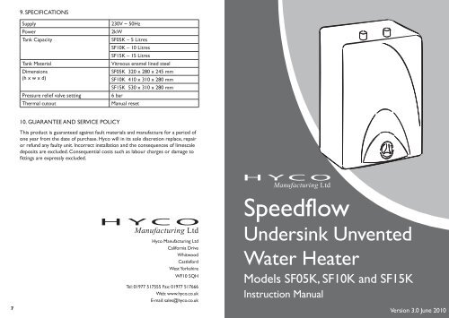
9. SPECIFICATIONS<br />
Supply<br />
Power<br />
Tank Capacity<br />
Tank Material<br />
Dimensions<br />
(h x w x d)<br />
Pressure relief valve setting<br />
Thermal cutout<br />
230V ~ 50Hz<br />
2kW<br />
<strong>SF05K</strong> – 5 Litres<br />
<strong>SF10K</strong> – 10 Litres<br />
<strong>SF15K</strong> – 15 Litres<br />
Vitreous enamel lined steel<br />
<strong>SF05K</strong> 320 x 280 x 245 mm<br />
<strong>SF10K</strong> 410 x 310 x 280 mm<br />
<strong>SF15K</strong> 530 x 310 x 280 mm<br />
6 bar<br />
<strong>Manual</strong> reset<br />
10. GUARANTEE AND SERVICE POLICY<br />
This product is guaranteed against fault materials <strong>and</strong> manufacture for a period of<br />
one year from the date of purchase. Hyco will in its sole discretion replace, repair<br />
or refund any faulty unit. Incorrect installation <strong>and</strong> the consequences of limescale<br />
deposits are excluded. Consequential costs such as labour charges or damage to<br />
fi ttings are expressly excluded.<br />
<strong>Speedflow</strong><br />
7<br />
Hyco Manufacturing Ltd<br />
California Drive<br />
Whitwood<br />
Castleford<br />
West Yorkshire<br />
WF10 5QH<br />
Tel: 01977 517555 Fax: 01977 517666<br />
Web: www.hyco.co.uk<br />
E-mail: sales@hyco.co.uk<br />
Undersink Unvented<br />
Water Heater<br />
Models <strong>SF05K</strong>, <strong>SF10K</strong> <strong>and</strong> <strong>SF15K</strong><br />
<strong>Instruction</strong> <strong>Manual</strong><br />
Version 3.0 June 2010
HYCO SPEEDFLOW UNVENTED WATER HEATER<br />
MODELS <strong>SF05K</strong> (5 Litres) <strong>SF10K</strong> (10 Litres) AND<br />
<strong>SF15K</strong> (15 Litres)<br />
1. INTRODUCTION<br />
Thank you for purchasing a Hyco Speedfl ow unvented water heater. This product<br />
operates at mains water pressure <strong>and</strong> can supply hot water using ordinary taps.<br />
CAUTION<br />
THE SPEEDFLOW MUST BE INSTALLED AND MAINTAINED BY<br />
A COMPETENT PERSON IN ACCORDANCE WITH CURRENT<br />
ELECTRICAL AND PLUMBING REGULATIONS.<br />
IT IS ESSENTIAL THAT THE ENCLOSED PRESSURE RELIEF VALVE<br />
IS FITTED<br />
MAKE PLUMBING CONNECTIONS WITH FLEXIBLE STAINLESS<br />
STEEL HOSES TO FACILITATE FUTURE MAINTENANCE<br />
ALWAYS FIT THE HEATER THE CORRECT WAY UP<br />
(PIPES SHOULD BE AT THE TOP)<br />
USE LOWEST ACCEPTABLE TEMPERATURE SETTING TO SAVE<br />
ENERGY AND REDUCE LIMESCALE<br />
DO NOT CONNECT TO POWER UNLESS UNIT IS FULL OF<br />
WATER – OPEN TAP AND ALLOW WATER TO FLOW FREELY<br />
TO CLEAR AIRLOCKS<br />
DO NOT SWITCH POWER ON IF WATER IN HEATER OR PIPES<br />
COULD BE FROZEN<br />
8. TROUBLE SHOOTING<br />
SYMPTOM POSSIBLE CAUSE SOLUTION<br />
Water constantly fl ows<br />
from pressure relief valve<br />
Water fl ows from<br />
pressure relief valve<br />
during heating cycle only<br />
Water is not heated<br />
Small volume of hot<br />
water<br />
Water appears to leak<br />
from heater<br />
Water pressure is too<br />
high (above 4 bar).<br />
Heated water cannot<br />
exp<strong>and</strong> back up inlet pipe<br />
due to obstruction.<br />
1. Thermal cut-out has<br />
tripped.<br />
If problems persist contact Hyco Technical Dept on 01977 517555.<br />
Fit Pressure Reducing<br />
Valve Kit (Hyco Kit SF4).<br />
Fit Expansion Vessel Kit<br />
(Hyco kit SF3).<br />
1. See section 6. Check<br />
heater is correct way<br />
up (pipes at top).<br />
2. Element has failed. 2. Replace element. See<br />
section 6 for access to<br />
element.<br />
3. Thermostat has failed. 3. Replace thermostat.<br />
1. Unit upside down. 1. Re-install correct way<br />
up.<br />
2. Thermostat set too<br />
low.<br />
2. Increase thermostat<br />
setting.<br />
3. Thermostat fault. 3. Replace thermostat.<br />
1. Poor connections to<br />
pipework.<br />
1. Check plumbing<br />
connections, especially<br />
those to inlet <strong>and</strong><br />
outlet.<br />
2. Element gasket leak. 2. Refi t gasket, tighten<br />
fl ange bolts evenly. Do<br />
not over tighten. See<br />
section 6 for access to<br />
element.<br />
2. INSTALLATION (WALL MOUNTING)<br />
The Speedfl ow is normally fi tted immediately below the outlet to be supplied, but<br />
it can be mounted above or to the side of the outlet provided it is vertical with<br />
the pipe outlets at the top. The unit can either be placed directly on the fl oor or<br />
fi xed to a wall using the mounting bracket supplied.<br />
ENSURE THE MOUNTING SURFACE IS STRONG ENOUGH TO<br />
SUPPORT THE SPEEDFLOW INCLUDING THE WEIGHT OF<br />
THE WATER.<br />
The 5 litre model (<strong>SF05K</strong>) can typically serve 1 sink, the 10 litre model (<strong>SF10K</strong>)<br />
can typically serve 1 or 2 sinks <strong>and</strong> the 15 litre model (<strong>SF15K</strong>) can typically serve<br />
2 or 3 depending on simultaneous usage.<br />
1 6
6. THERMAL CUTOUT RESET, ELEMENT REPLACEMENT<br />
AND ANODE REPLACEMENT (continued)<br />
To reset the cutout, depress the button in the centre of the device. If the device<br />
has tripped reduce the thermostat setting if possible.<br />
If the device trips repeatedly with a low thermostat setting, contact Hyco<br />
Technical Department on 01977 517555.<br />
To access the element or anode, unscrew the bolts holding the fl ange in position.<br />
The element <strong>and</strong> anode can then be removed. Reverse to re-fi t.<br />
7. MAINTENANCE<br />
A grey cylindrical magnesium sacrifi cial anode is fi tted to the element to aid<br />
tank corrosion resistance. The anode condition should be inspected annually <strong>and</strong><br />
replaced if the there are signs of signifi cant corrosion.<br />
The pressure relief valve should be checked annually by twisting the cap <strong>and</strong><br />
verifying water is discharged.<br />
3. PLUMBING CONNECTIONS<br />
A service valve should be fi tted to allow / facilitate future maintenance.<br />
THE SUPPLIED 6 BAR PRESSURE RELIEF VALVE MUST ALWAYS BE<br />
FITTED. THERE MUST BE NO OBSTRUCTIONS IN THE<br />
PIPEWORK BETWEEN THE HEATER AND THE RELIEF VALVE.<br />
THE RELIEF VALVE MUST DISCHARGE TO A SAFE AND VISIBLE<br />
PLACE.<br />
The hot <strong>and</strong> cold fittings are ½” BSP <strong>and</strong> are at the top of the unit. These<br />
connections are colour coded (blue = cold, red = hot). They are not<br />
interchangeable.<br />
The fi nal connection of the Speedfl ow to pipework should be implemented with<br />
fl exible stainless steel hoses.<br />
OPEN HOT WATER TAP AND ALLOW WATER TO RUN<br />
THROUGH FOR AT LEAST 5 SECONDS TO CLEAR AIRLOCKS.<br />
Depending on the installation circumstances, other accessories may be required.<br />
If required, these must be ordered separately <strong>and</strong> are installed as shown on the<br />
diagrams below <strong>and</strong> on the next page. Water pressure can increase considerably<br />
at night when dem<strong>and</strong> is low, so a pressure reducing valve may be required even if<br />
there is no obvious problem at installation.<br />
DIAGRAM A - Pressure below 4.2 bar<br />
1.4 (5L), 2.8 (10L) or 4.2 (15L)<br />
metres is required for expansion<br />
in pipework<br />
No accessories needed<br />
5<br />
2
DIAGRAM B - Cold draw off nearby<br />
5. OPERATION<br />
Switch on the mains supply. The external neon lamp indicates when the element<br />
is heating.<br />
USE THE LOWEST ACCEPTABLE TEMPERATURE SETTING TO<br />
SAVE ENERGY.<br />
DIAGRAM C - Pressure above 4.2 bar<br />
4. ELECTRICAL INSTALLATION<br />
Accessory SF3 needed to prevent exp<strong>and</strong>ed<br />
warm water entering cold water supply.<br />
Kit comprises expansion vessel <strong>and</strong> check valve.<br />
Installation must comply with the latest IEE regulations.<br />
Accessory SF4 needed to prevent pressure<br />
relief valve discharging constantly<br />
Kit comprises pressure reducing valve,<br />
expansion vessel <strong>and</strong> check valve<br />
HOT WATER MAY PRESENT A SCALDING HAZARD, ESPECIALLY<br />
TO CHILDREN OR THE INFIRM. A THERMOSTATIC BLENDING<br />
VALVE IS RECOMMENDED IN HIGH RISK SITUATIONS.<br />
6. THERMAL CUTOUT RESET, ELEMENT REPLACEMENT<br />
AND ANODE REPLACEMENT<br />
DISCONNECT ELECTRICITY SUPPLY BEFORE MAINTENANCE.<br />
A re-settable safety thermal cut-out switches off the element in the event of the<br />
unit over-heating.<br />
The thermal cut-out may trip occasionally in normal use. If this happens the heater<br />
will not heat water <strong>and</strong> the element light will not come on.<br />
The thermal cut-out is located underneath the unit behind the grey access plate.<br />
Depending on the mounting position of the unit, you may need to uninstall the<br />
unit for ease of access to the cutout.<br />
In these cases, disconnect electricity supply <strong>and</strong> unscrew fl exible hose connectors.<br />
Drain water from heater <strong>and</strong> locate grey access plate.<br />
Remove the cover retaining screws <strong>and</strong> gently prise cover off.<br />
The thermal cut-out will be visible, as shown below.<br />
Thermal cutout -<br />
Press to reset.<br />
3<br />
Connection should be to a fused switched 13A spur. If the cable length is<br />
insuffi cient, it is recommended that the entire cable is replaced <strong>and</strong> no joins made<br />
to the original.<br />
This product must be earthed.<br />
IMPORTANT: DO NOT SWITCH THE HEATER ON UNLESS YOU ARE<br />
CERTAIN THAT IT IS COMPLETELY FULL OF WATER. FAILURE TO DO SO<br />
WILL VOID THE WARRANTY.<br />
Element fl ange - remove to access anode.<br />
Element securing bolt (x4)<br />
Allen key required to remove.<br />
4