AquaFlex® Stainless Steel Sprinkler Fittings I-AQUAFLEX - Victaulic
AquaFlex® Stainless Steel Sprinkler Fittings I-AQUAFLEX - Victaulic
AquaFlex® Stainless Steel Sprinkler Fittings I-AQUAFLEX - Victaulic

You also want an ePaper? Increase the reach of your titles
YUMPU automatically turns print PDFs into web optimized ePapers that Google loves.
INSTALLATION INSTRUCTIONS<br />
I-<strong>AQUAFLEX</strong><br />
AquaFlex ® <strong>Stainless</strong> <strong>Steel</strong> <strong>Sprinkler</strong> <strong>Fittings</strong><br />
WARNING<br />
• Read and understand all instructions<br />
before attempting to install any <strong>Victaulic</strong><br />
AquaFlex ® products.<br />
• Wear safety glasses, hardhat, and foot<br />
protection during installation.<br />
Failure to follow these instructions could<br />
cause improper sprinkler operation, resulting<br />
in serious personal injury and/or property<br />
damage.<br />
WARNING<br />
• These installation instructions are intended for an experienced,<br />
trained installer.<br />
• The user must understand the purpose of these products,<br />
c ommon industry standards for safety, and the potential<br />
consequences of improper product installation.<br />
Failure to follow these instructions could cause improper sprinkler<br />
operation, resulting in serious personal injury and/or property<br />
damage.<br />
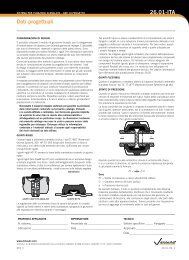
INTRODUCTION<br />
AquaFlex <strong>Stainless</strong> <strong>Steel</strong> <strong>Sprinkler</strong> <strong>Fittings</strong> connect the branch line<br />
to the sprinkler using a flexible stainless steel hose and reducer.<br />
The flexible stainless steel hose and fittings are intended for direct<br />
connection to the sprinkler and are particularly suited for use in<br />
suspended ceiling applications. Each drop assembly comes with one<br />
stainless steel flexible hose, one branch line connection nipple, one<br />
sprinkler reducing nipple, and the 1BEE 2 One-Piece Bracket or the Hat<br />
Channel Bracket.<br />
<strong>Victaulic</strong> AquaFlex unbraided flexible stainless steel hoses are cULus<br />
Listed, City of Los Angeles (RR5659) Approved, and accepted for use<br />
by the City of New York Department of Buildings (MEA 60-05-E).<br />
<strong>Victaulic</strong> AquaFlex braided flexible stainless steel hoses are FM<br />
Approved, City of Los Angeles (RR5659) Approved, and accepted for<br />
use by the City of New York Department of Buildings (MEA 60-05-E).<br />
Flexible stainless steel hoses are available in lengths from 31 - 72<br />
inches/787 - 1829 mm with either 1/2-inch or 3/4-inch NPT threaded<br />
outlets.<br />
TECHNICAL DATA<br />
Maximum Working Pressure:<br />
200 psi/1375 kPa (FM Approval for Braided System)<br />
175 psi/1206 kPa (UL Listing for Unbraided System)<br />
Maximum Ambient Temperature: 225° F/107° C<br />
Connection to Branch Line: 1-inch NPT/BSPT<br />
Minimum Bend Radius of Flexible <strong>Stainless</strong> <strong>Steel</strong> Hose:<br />
7 inches/178 mm (FM Approval for Braided System)<br />
4 inches/102 mm (UL Listing for Unbraided System)<br />
Maximum Number of 90° Bends Per Flexible <strong>Stainless</strong> <strong>Steel</strong> Hose:<br />
Refer to the “Friction Loss Data” section on page 2. NOTE: The<br />
flexible stainless steel hose should not be bent within<br />
2 1/2 inches/64 mm of the connection nut at both ends.<br />
Maximum K-Factor of <strong>Sprinkler</strong> to be Connected to <strong>Sprinkler</strong><br />
Reducing Nipple for Unbraided System:<br />
5.6 for 1/2-inch<br />
8.0 for 3/4-inch<br />
Maximum K-Factor of <strong>Sprinkler</strong> to be Connected to <strong>Sprinkler</strong><br />
Reducing Nipple for Braided System:<br />
5.6 for 1/2-inch<br />
14.0 for 3/4-inch<br />
IMPORTANT INSTALLATION INFORMATION<br />
• <strong>Victaulic</strong> AquaFlex products must be installed according to<br />
current, applicable National Fire Protection Association (NFPA<br />
13, 13D, 13R, etc.) standards or equivalent standards for wet or<br />
dry systems. Deviations from these standards or alterations to<br />
AquaFlex products or sprinklers will void any <strong>Victaulic</strong> warranty. In<br />
addition, installations must meet provisions of the local authority<br />
having jurisdiction and local codes, as applicable.<br />
• If intended for use with drop ceilings, reference must be made to<br />
specific ceiling constructions, such as intermediate and heavyduty<br />
ceilings as described in the Standard Specification for the<br />
Manufacture, Performance, and Testing of Metal Suspension<br />
Systems for Acoustical Tile and Lay-In Panel Ceilings (ASTM<br />
C635) when installed in accordance with the Standard Practice for<br />
Installation of Metal Ceiling Suspension Systems for Acoustical Tile<br />
and Lay-In Panels (ASTM C636).<br />
• <strong>Victaulic</strong> AquaFlex <strong>Stainless</strong> <strong>Steel</strong> <strong>Sprinkler</strong> <strong>Fittings</strong> and/or the<br />
1BEE 2 One-Piece Bracket or Hat Channel Bracket must not be<br />
intermixed with other manufacturer’s products.<br />
• Refer to the specific product submittal for applications and<br />
listing information. These submittals are located in Sections<br />
10 and 40 of the <strong>Victaulic</strong> G-100 Catalog or on the <strong>Victaulic</strong><br />
website at www.victaulic.com. In addition, when installing<br />
<strong>Victaulic</strong> FireLock® Automatic <strong>Sprinkler</strong>s with <strong>Victaulic</strong><br />
AquaFlex <strong>Stainless</strong> <strong>Steel</strong> <strong>Sprinkler</strong> <strong>Fittings</strong>, refer to the I-40<br />
Installation and Maintenance Instructions for details on sprinkler<br />
installation requirements.<br />
• Size the piping system to provide the minimum required flow rate<br />
for the sprinkler system.<br />
• Flush the system to remove foreign material. Continue to flush the<br />
system until water runs clear.<br />
• DO NOT install sprinkler system piping through heating ducts.<br />
DO NOT connect sprinkler system piping to domestic hot water<br />
systems. DO NOT install sprinklers where they will be exposed<br />
to temperatures that exceed the maximum ambient temperature<br />
rating for the sprinkler.<br />
• The flexible stainless steel hose should not be bent or fluctuated<br />
up-and-down or side-to-side when it is pressurized for test.<br />
• The flexible stainless steel hose should not be bent within<br />
2 1/2 inches/64 mm of the connection nut at both ends.<br />
• Flexible stainless steel hose and fittings have limited flexibility and<br />
are intended only to be installed with bends at their respective<br />
minimum bend radii.<br />
• Protect wet piping systems from freezing temperatures.<br />
“Important Installation Information” continued on the following page<br />
www.victaulic.com<br />
VICTAULIC AND <strong>AQUAFLEX</strong> ARE REGISTERED TRADEMARKS OF VICTAULIC COMPANY. © 2010 VICTAULIC COMPANY. ALL RIGHTS RESERVED. PRINTED IN THE USA.<br />
REV_C
INSTALLATION INSTRUCTIONS<br />
AquaFlex ® <strong>Stainless</strong> <strong>Steel</strong> <strong>Sprinkler</strong> <strong>Fittings</strong><br />
I-<strong>AQUAFLEX</strong><br />
• If construction is altered, refer to applicable standards to determine<br />
if additional sprinklers are required.<br />
• The owner is responsible for maintaining the fire protection system<br />
in proper operating condition.<br />
• For minimum maintenance and inspection requirements, refer<br />
to NFPA 25 and the NFPA pamphlet that describes the care<br />
and maintenance of sprinkler systems. In addition, the authority<br />
having jurisdiction may have additional maintenance, testing, and<br />
inspection requirements that must be followed.<br />
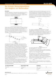
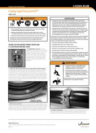
STAINLESS STEEL FLEXIBLE HOSE BEND<br />
CHARACTERISTICS<br />
Minimum<br />
bend radius<br />
90°<br />
2X<br />
Minimum<br />
bend radius<br />
Minimum<br />
bend radius<br />
WARNING<br />
• Re-location of AquaFlex products MUST be performed by<br />
qualified personnel familiar with the system’s original design<br />
criteria, sprinkler listings/approvals, and state and local codes<br />
(including NFPA 13 standards).<br />
Failure to re-locate this AquaFlex product properly could affect its<br />
performance during a fire, resulting in serious personal injury and<br />
property damage.<br />
2X<br />
Minimum<br />
bend radius<br />
OR<br />
Minimum<br />
bend radius<br />
OR<br />
Minimum<br />
bend radius<br />
Minimum<br />
bend radius<br />
Minimum<br />
bend radius<br />
Minimum<br />
bend radius<br />
FRICTION LOSS DATA<br />
Length of <strong>Stainless</strong> <strong>Steel</strong><br />
Flexible Hose<br />
Actual Length of <strong>Stainless</strong> <strong>Steel</strong> Flexible Hose<br />
inches/mm<br />
Outlet Size<br />
NOTE: For out-of-plane (three-dimensional) bends, care must be taken<br />
to avoid imparting torque on the flexible stainless steel hose.<br />
Equivalent Length of 1-inch/33.7-mm<br />
Schedule 40 Pipe<br />
feet/meters<br />
inches FM UL inches FM* UL‡<br />
24 N/A<br />
28<br />
1/2<br />
N/A<br />
18<br />
5.5<br />
700<br />
32<br />
3/4<br />
N/A<br />
9.8<br />
31<br />
31<br />
790<br />
31<br />
1/2<br />
9.6 27<br />
2.9 8.2<br />
780<br />
3/4<br />
8.2<br />
2.5<br />
33<br />
10.1<br />
36<br />
36<br />
915<br />
40<br />
1/2<br />
1000<br />
9.9 48<br />
3/4<br />
3.0 14.6<br />
11.0<br />
3.4<br />
44<br />
13.4<br />
48<br />
48<br />
1220<br />
17.1 53<br />
48<br />
1/2<br />
5.2 16.2<br />
1220<br />
16.5 55<br />
3/4<br />
5.0 16.8<br />
60<br />
21.4 68<br />
60<br />
61<br />
1/2<br />
6.5 20.7<br />
1525<br />
1540<br />
20.1 63<br />
3/4<br />
6.1 19.2<br />
72<br />
72<br />
1830<br />
27.3 73<br />
72<br />
1/2<br />
8.3 22.3<br />
1830<br />
26.2 76<br />
3/4<br />
7.9 23.2<br />
Maximum Number<br />
of 90° Bends at<br />
4-inch/102-mm<br />
Bend Radius §<br />
‡ Series AQU at 4-inch/102-mm minimum bend radius and straight reducers<br />
* Series AQB at 7-inch/178-mm minimum bend radius and straight reducers<br />
§ A higher number of bends may be permitted, provided the sum of degrees is equal to or less than the total maximum allowable degrees of bend (e.g. Two<br />
90° bends equal 180°. Three 90° bends equal 270°).<br />
For friction loss data for elbows, refer to <strong>Victaulic</strong> submittal 10.85.<br />
EXAMPLE: A 48-inch Series AQU hose installed with two 30° bends and two 90° bends at a 4-inch bend radius is permitted and considered equivalent to the<br />
data in the table shown above. In this example, the total number of degrees is 240°, which is less than the allowable 270°.<br />
NOTE: Differences in equivalent lengths are due to varying test methods, per UL 2443 and FM 1637 standards. Refer to these standards for additional<br />
information regarding friction loss test methods.<br />
2<br />
2<br />
3<br />
3<br />
3<br />
3<br />
www.victaulic.com<br />
VICTAULIC AND <strong>AQUAFLEX</strong> ARE REGISTERED TRADEMARKS OF VICTAULIC COMPANY. © 2010 VICTAULIC COMPANY. ALL RIGHTS RESERVED. PRINTED IN THE USA.<br />
I-<strong>AQUAFLEX</strong>_2<br />
REV_C
INSTALLATION INSTRUCTIONS<br />
AquaFlex ® <strong>Stainless</strong> <strong>Steel</strong> <strong>Sprinkler</strong> <strong>Fittings</strong><br />
I-<strong>AQUAFLEX</strong><br />
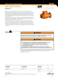
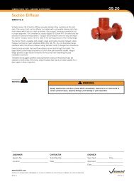
ASSEMBLY DRAWINGS – 1BEE 2 ONE-PIECE BRACKET<br />
<strong>Stainless</strong> <strong>Steel</strong><br />
Flexible Tube<br />
Branch Line<br />
Connection<br />
Nut<br />
Branch Line<br />
Connection<br />
Nipple<br />
1BEE One-Piece<br />
Bracket Assembly<br />
Connection<br />
Nut<br />
<strong>Sprinkler</strong><br />
Reducing Nipple<br />
Wing Nut<br />
Center Gate<br />
Assembly with<br />
Wing Nut<br />
ASTM C635<br />
Ceiling/Rail<br />
Assembly<br />
#8 x ½-inch<br />
Self-Drilling Screw<br />
<strong>Sprinkler</strong><br />
3<br />
4<br />
2<br />
1<br />
Item Description<br />
1 24-inch/610-mm or 48-inch/1219-mm<br />
Long Square Bar<br />
2 Center Gate Assembly with Wing Nut<br />
3 End Bracket Assembly with Wing Nut<br />
4 Sheet Metal Screw<br />
4<br />
3<br />
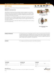
ASSEMBLY DRAWINGS – HAT CHANNEL BRACKET<br />
1<br />
Item Description<br />
1 24-inch/610-mm or 48-inch/1219-mm<br />
Long Square Bar<br />
2 Center Gate Assembly with Wing Nut<br />
3 Wing Nut Bolt with Cup Point<br />
4 Hat Channel End Bracket<br />
5 Wing Nut Bolt with Cone Point<br />
6 Self-Drilling Screw (#10-16 x ½-inch)<br />
2<br />
6<br />
3<br />
4<br />
5<br />
www.victaulic.com<br />
VICTAULIC AND <strong>AQUAFLEX</strong> ARE REGISTERED TRADEMARKS OF VICTAULIC COMPANY. © 2010 VICTAULIC COMPANY. ALL RIGHTS RESERVED. PRINTED IN THE USA.<br />
REV_C<br />
I-<strong>AQUAFLEX</strong>_3
INSTALLATION INSTRUCTIONS<br />
I-<strong>AQUAFLEX</strong><br />
AquaFlex ® <strong>Stainless</strong> <strong>Steel</strong> <strong>Sprinkler</strong> <strong>Fittings</strong><br />
INSTALLATION FOR ASTM C635 METAL<br />
CEILING SUSPENSION SYSTEMS INSTALLED IN<br />
ACCORDANCE WITH ASTM C636 STANDARDS<br />
WARNING<br />
• The flexible stainless steel hose should not be bent or<br />
fluctuated up-and-down or side-to-side when it is pressurized<br />
for test.<br />
• The flexible stainless steel hose should not be bent within<br />
2 1/2 inches/64 mm of the connection nut at both ends.<br />
Failure to follow these instructions could cause improper sprinkler<br />
operation, resulting in serious personal injury and/or property<br />
damage.<br />
3. Connect the nut of the flexible stainless steel hose to the sprinkler<br />
reducing nipple. DO NOT use pipe joint compound or Teflon*<br />
tape on the fine threads of the sprinkler reducing nipple, since the<br />
flat gasket on the end of the flexible stainless steel hose provides<br />
the leak-proof connection. Tighten the connection to a maximum<br />
torque of 15 ft-lbs/20 N•m. NOTE: To prevent damage to the seal,<br />
DO NOT exceed the specified torque on the nut.<br />
1. Apply pipe joint compound or Teflon* tape to the tapered threads<br />
of the branch line connection nipple. NOTE: DO NOT use a<br />
combination of pipe joint compound and tape. Using a pipe<br />
wrench, tighten the branch line connection nipple into the branch<br />
line.<br />
2. Connect the nut of the flexible stainless steel hose to the branch<br />
line connection nipple, as shown above. DO NOT use pipe joint<br />
compound or Teflon* tape on the threads of the branch line<br />
connection nipple, since the flat gasket on the end of the flexible<br />
stainless steel hose provides the leak-proof connection. Tighten<br />
the connection to a maximum torque of 15 ft-lbs/20 N•m. NOTE:<br />
To prevent damage to the seal, DO NOT exceed the specified<br />
torque on the nut.<br />
* Teflon is a registered trademark of the DuPont Company<br />
4. Attach the end brackets of the 1BEE 2 One-Piece Bracket to the<br />
rails of an ASTM C635 metal ceiling suspension system installed<br />
in accordance with ASTM C636 standards. Make sure the ends of<br />
the 1BEE 2 One-Piece Bracket engage the rails, as shown above.<br />
Tighten the wing nuts to a torque of 3 ft-lbs/4 N•m to secure the<br />
ends to the rails.<br />
www.victaulic.com<br />
VICTAULIC AND <strong>AQUAFLEX</strong> ARE REGISTERED TRADEMARKS OF VICTAULIC COMPANY. © 2010 VICTAULIC COMPANY. ALL RIGHTS RESERVED. PRINTED IN THE USA.<br />
I-<strong>AQUAFLEX</strong>_4<br />
REV_C
INSTALLATION INSTRUCTIONS<br />
I-<strong>AQUAFLEX</strong><br />
AquaFlex ® <strong>Stainless</strong> <strong>Steel</strong> <strong>Sprinkler</strong> <strong>Fittings</strong><br />
5. For installations that must meet cULus Listing requirements, or for<br />
added tamper resistance, tighten a #8 x 1/2-inch self-drilling screw<br />
through the 1BEE 2 One-Piece Bracket and ceiling grid at the two<br />
locations on the bracket. NOTE: A tamper-evident label is available<br />
and can be applied to one or both of the end brackets.<br />
7. Apply pipe joint compound or Teflon* tape to the male threads of<br />
the sprinkler. Install the sprinkler into the sprinkler reducing nipple<br />
by following the sprinkler manufacturer’s installation instructions.<br />
8. After installation is complete, test the system for leaks in<br />
accordance with NFPA guidelines.<br />
6. Move the center gate assembly of the 1BEE 2 One-Piece Bracket to<br />
the desired location, then slide the sprinkler reducing nipple into<br />
the center gate assembly.<br />
6a. Close the gate around the sprinkler reducing nipple. Swing the<br />
pivot screw into the slot on the gate, and tighten the wing nut to a<br />
torque of 3 ft-lbs/4 N•m to secure the sprinkler reducing nipple in<br />
the desired location. NOTE: The pivot screw is staked to prevent<br />
the wing nut from being backed off/removed completely.<br />
* Teflon is a registered trademark of the DuPont Company<br />
www.victaulic.com<br />
VICTAULIC AND <strong>AQUAFLEX</strong> ARE REGISTERED TRADEMARKS OF VICTAULIC COMPANY. © 2010 VICTAULIC COMPANY. ALL RIGHTS RESERVED. PRINTED IN THE USA.<br />
REV_C<br />
I-<strong>AQUAFLEX</strong>_5
INSTALLATION INSTRUCTIONS<br />
I-<strong>AQUAFLEX</strong><br />
AquaFlex ® <strong>Stainless</strong> <strong>Steel</strong> <strong>Sprinkler</strong> <strong>Fittings</strong><br />
2 X 4 WOOD JOIST/STUD INSTALLATION<br />
(FM ONLY)<br />
1. Perform steps 1 - 3 of the “Installation for ASTM C635 Metal<br />
Ceiling Suspension Systems Installed in Accordance with ASTM<br />
C636 Standards” section.<br />
2 X 4 METAL JOIST/STUD INSTALLATION<br />
(FM ONLY)<br />
1. Perform steps 1 - 3 of the “Installation for ASTM C635 Metal<br />
Ceiling Suspension Systems Installed in Accordance with ASTM<br />
C636 Standards” section.<br />
2. Remove the sheet metal screw from only one end bracket<br />
assembly of the 1BEE 2 One-Piece Bracket.<br />
2a. Remove the wing nut from each of the end bracket assemblies.<br />
3. Place the end bracket assembly (with the sheet metal screw still<br />
installed) up against the outside surface of the wood joist/stud with<br />
the square bar resting on top of the wood joists/studs.<br />
3a. Slide the end bracket assembly (with the sheet metal screw<br />
removed in step 2) toward the outside surface of the opposite<br />
wood joist/stud, as shown in the graphic below.<br />
2. Remove the sheet metal screw from only one end bracket<br />
assembly of the 1BEE 2 One-Piece Bracket. Slide the end bracket<br />
assembly toward the center of the square bar.<br />
2a. Remove the wing nut from each of the end bracket assemblies.<br />
3. Place the end bracket assembly (with the sheet metal screw still<br />
installed) up against the outside surface of the metal joist/stud with<br />
the square bar resting on top of the metal joists/studs.<br />
3a. Slide the end bracket assembly (with the sheet metal screw<br />
removed in step 2) toward the inside, flat surface of the opposite<br />
metal joist/stud, as shown in the graphic below.<br />
1½-inch/38-mm Long<br />
#10 Wood Screw<br />
(4 Total)<br />
1¼-inch/32-mm<br />
Long #10<br />
Self-Drilling<br />
Sheet Metal<br />
Screws<br />
(4 Total)<br />
4. Install the modified 1BEE 2 One-Piece Bracket assembly to the<br />
wood joists/studs by using four, 1 1/2-inch/38-mm long #10 wood<br />
screws in the locations noted in the graphic shown above.<br />
5. Using an 1/8-inch/3-mm drill bit, drill a hole down through the end<br />
bracket assembly (with the sheet metal screw removed in step<br />
2) and into the square bar to accommodate re-installation of the<br />
sheet metal screw.<br />
6. Re-install the sheet metal screw into the end bracket assembly/<br />
square bar.<br />
7. Perform steps 6 - 8 of the “Installation for ASTM C635 Metal<br />
Ceiling Suspension Systems Installed in Accordance with ASTM<br />
C636 Standards” section to complete the installation.<br />
NOTE: For wood joists/studs larger than 2 x 4, longer sprinkler reducing<br />
nipples should be used.<br />
4. Install the modified 1BEE 2 One-Piece Bracket assembly to the<br />
metal joists/studs by using four, 1 1/4-inch/32-mm long #10 selfdrilling<br />
sheet metal screws in the locations noted in the graphic<br />
shown above.<br />
5. Using an 1/8-inch/3-mm drill bit, drill a hole down through the end<br />
bracket assembly (with the sheet metal screw removed in step<br />
2) and into the square bar to accommodate re-installation of the<br />
sheet metal screw.<br />
6. Re-install the sheet metal screw into the end bracket assembly/<br />
square bar.<br />
7. Perform steps 6 - 8 of the “Installation for ASTM C635 Metal<br />
Ceiling Suspension Systems Installed in Accordance with ASTM<br />
C636 Standards” section to complete the installation.<br />
NOTE: For metal joists/studs larger than 2 x 4, longer sprinkler reducing<br />
nipples should be used.<br />
www.victaulic.com<br />
VICTAULIC AND <strong>AQUAFLEX</strong> ARE REGISTERED TRADEMARKS OF VICTAULIC COMPANY. © 2010 VICTAULIC COMPANY. ALL RIGHTS RESERVED. PRINTED IN THE USA.<br />
I-<strong>AQUAFLEX</strong>_6<br />
REV_C
INSTALLATION INSTRUCTIONS<br />
I-<strong>AQUAFLEX</strong><br />
AquaFlex ® <strong>Stainless</strong> <strong>Steel</strong> <strong>Sprinkler</strong> <strong>Fittings</strong><br />
ALTERNATIVE WOOD JOIST/STUD INSTALLATION<br />
(FM ONLY)<br />
1. Perform steps 1 - 3 of the “Installation for ASTM C635 Metal<br />
Ceiling Suspension Systems Installed in Accordance with ASTM<br />
C636 Standards” section.<br />
ALTERNATIVE METAL JOIST/STUD INSTALLATION<br />
(FM ONLY)<br />
1. Perform steps 1 - 3 of the “Installation for ASTM C635 Metal<br />
Ceiling Suspension Systems Installed in Accordance with ASTM<br />
C636 Standards” section.<br />
2. Remove the sheet metal screw from only one end bracket<br />
assembly of the 1BEE 2 One-Piece Bracket. Remove the end<br />
bracket assembly from the square bar.<br />
2a. Remove the wing nut from each of the end bracket assemblies.<br />
3. Measure the distance between the wood joists/studs.<br />
3a. Cut the square bar to the length needed to fit between the two<br />
wood joists/studs. This length must be measured from the outside<br />
of the end bracket assembly (with the wing nut removed) to the<br />
point on the square bar that will butt up against the other wood<br />
joist/stud.<br />
4. Place the end bracket assembly, removed in step 2, onto the end<br />
of the square bar so that the square bar is flush with the outside<br />
of the end bracket assembly. Mark the new location where the<br />
sheet metal screw will be re-installed. Drill an 1/8-inch/3-mm hole at<br />
the mark on the square bar to accommodate re-installation of the<br />
sheet metal screw.<br />
5. Re-install the end bracket assembly to the square bar with the<br />
sheet metal screw removed in step 2.<br />
2. Remove the sheet metal screw from only one end bracket<br />
assembly of the 1BEE 2 One-Piece Bracket. Remove the end<br />
bracket assembly from the square bar.<br />
2a. Remove the wing nut from each of the end bracket assemblies.<br />
3. Measure the distance between the metal joists/studs.<br />
3a. Cut the square bar to the length needed to fit between the two<br />
metal joists/studs. This length must be measured from the outside<br />
of the end bracket assembly (with the wing nut removed) to the<br />
point on the square bar that will butt up against the other metal<br />
joist/stud.<br />
4. Place the end bracket assembly, removed in step 2, onto the end<br />
of the square bar so that the square bar is flush with the outside<br />
of the end bracket assembly. Mark the new location where the<br />
sheet metal screw will be re-installed. Drill an 1/8-inch/3-mm hole at<br />
the mark on the square bar to accommodate re-installation of the<br />
sheet metal screw.<br />
5. Re-install the end bracket assembly to the square bar with the<br />
sheet metal screw removed in step 2.<br />
1½-inch/38-mm Long<br />
#10 Wood Screw<br />
(4 Total)<br />
1¼-inch/32-mm<br />
Long #10<br />
Self-Drilling<br />
Sheet Metal<br />
Screws<br />
(4 Total)<br />
6. Install the modified 1BEE 2 One-Piece Bracket assembly between<br />
the wood joists/studs by using four, 1 1/2-inch/38-mm long #10<br />
wood screws in the locations noted in the graphic shown above.<br />
7. Perform steps 6 - 8 of the “Installation for ASTM C635 Metal<br />
Ceiling Suspension Systems Installed in Accordance with ASTM<br />
C636 Standards” section to complete the installation.<br />
6. Install the modified 1BEE 2 One-Piece Bracket assembly between<br />
the metal joists/studs by using four, 1 1/4-inch/32-mm long #10 selfdrilling<br />
sheet metal screws in the locations noted in the graphic<br />
shown above.<br />
7. Perform steps 6 - 8 of the “Installation for ASTM C635 Metal<br />
Ceiling Suspension Systems Installed in Accordance with ASTM<br />
C636 Standards” section to complete the installation.<br />
www.victaulic.com<br />
VICTAULIC AND <strong>AQUAFLEX</strong> ARE REGISTERED TRADEMARKS OF VICTAULIC COMPANY. © 2010 VICTAULIC COMPANY. ALL RIGHTS RESERVED. PRINTED IN THE USA.<br />
REV_C<br />
I-<strong>AQUAFLEX</strong>_7
INSTALLATION INSTRUCTIONS<br />
I-<strong>AQUAFLEX</strong><br />
AquaFlex ® <strong>Stainless</strong> <strong>Steel</strong> <strong>Sprinkler</strong> <strong>Fittings</strong><br />
INSTALLATION FOR ASTM C645 HAT FURRING<br />
CHANNEL CEILING SYSTEMS INSTALLED IN<br />
ACCORDANCE WITH ASTM C754 STANDARDS<br />
(FM ONLY)<br />
WARNING<br />
• The flexible stainless steel hose should not be bent or<br />
fluctuated up-and-down or side-to-side when it is pressurized<br />
for test.<br />
• The flexible stainless steel hose should not be bent within<br />
2 1/2 inches/64 mm of the connection nut at both ends.<br />
Failure to follow these instructions could cause improper sprinkler<br />
operation, resulting in serious personal injury and/or property<br />
damage.<br />
3. Connect the nut of the flexible stainless steel hose to the sprinkler<br />
reducing nipple. DO NOT use pipe joint compound or Teflon*<br />
tape on the fine threads of the sprinkler reducing nipple, since the<br />
flat gasket on the end of the flexible stainless steel hose provides<br />
the leak-proof connection. Tighten the connection to a maximum<br />
torque of 15 ft-lbs/20 N•m. NOTE: To prevent damage to the seal,<br />
DO NOT exceed the specified torque on the nut.<br />
1. Apply pipe joint compound or Teflon* tape to the tapered threads<br />
of the branch line connection nipple. NOTE: DO NOT use a<br />
combination of pipe joint compound and tape. Using a pipe<br />
wrench, tighten the branch line connection nipple into the branch<br />
line.<br />
2. Connect the nut of the flexible stainless steel hose to the branch<br />
line connection nipple, as shown above. DO NOT use pipe joint<br />
compound or Teflon* tape on the threads of the branch line<br />
connection nipple, since the flat gasket on the end of the flexible<br />
stainless steel hose provides the leak-proof connection. Tighten<br />
the connection to a maximum torque of 15 ft-lbs/20 N•m. NOTE:<br />
To prevent damage to the seal, DO NOT exceed the specified<br />
torque on the nut.<br />
4. Attach the end brackets to the ASTM C645 hat furring channel<br />
ceiling system installed in accordance with ASTM C754 standards.<br />
Make sure the end brackets engage the hat furring channels,<br />
as shown above. Tighten the wing nuts loosely to maintain<br />
engagement with the hat furring channels. The wing nuts will be<br />
tightened completely in later steps.<br />
* Teflon is a registered trademark of the DuPont Company<br />
www.victaulic.com<br />
VICTAULIC AND <strong>AQUAFLEX</strong> ARE REGISTERED TRADEMARKS OF VICTAULIC COMPANY. © 2010 VICTAULIC COMPANY. ALL RIGHTS RESERVED. PRINTED IN THE USA.<br />
I-<strong>AQUAFLEX</strong>_8<br />
REV_C
INSTALLATION INSTRUCTIONS<br />
I-<strong>AQUAFLEX</strong><br />
AquaFlex ® <strong>Stainless</strong> <strong>Steel</strong> <strong>Sprinkler</strong> <strong>Fittings</strong><br />
5. Place the center gate assembly onto the square bar, as shown<br />
above.<br />
7. Adjust the bracket assembly to the appropriate location on the hat<br />
furring channel.<br />
8. Tighten the wing nut on the side of each end bracket to a torque<br />
of 3 ft-lbs/4 N•m to secure the end brackets to the hat furring<br />
channels.<br />
6. Insert the square bar/center gate assembly into each end bracket,<br />
as shown above.<br />
9. Tighten the wing nut on the top of each end bracket to a torque of<br />
3 ft-lbs/4 N•m to secure the end brackets to the square bar.<br />
www.victaulic.com<br />
VICTAULIC AND <strong>AQUAFLEX</strong> ARE REGISTERED TRADEMARKS OF VICTAULIC COMPANY. © 2010 VICTAULIC COMPANY. ALL RIGHTS RESERVED. PRINTED IN THE USA.<br />
REV_C<br />
I-<strong>AQUAFLEX</strong>_9
INSTALLATION INSTRUCTIONS<br />
I-<strong>AQUAFLEX</strong><br />
AquaFlex ® <strong>Stainless</strong> <strong>Steel</strong> <strong>Sprinkler</strong> <strong>Fittings</strong><br />
10. Tighten a #10-16 x 1/2-inch self-drilling screw through the two<br />
locations on each end bracket and into the hat furring channels.<br />
11a. Close the gate around the sprinkler reducing nipple. Swing the<br />
pivot screw into the slot on the gate, and tighten the wing nut to a<br />
torque of 3 ft-lbs/4 N•m to secure the sprinkler reducing nipple in<br />
the desired location. NOTE: The pivot screw is staked to prevent<br />
the wing nut from being backed off/removed completely.<br />
12. Apply pipe joint compound or Teflon* tape to the male threads of<br />
the sprinkler. Install the sprinkler into the sprinkler reducing nipple<br />
by following the sprinkler manufacturer’s installation instructions.<br />
13. After installation is complete, test the system for leaks in<br />
accordance with NFPA guidelines.<br />
11. Move the center gate assembly to the desired location, then slide<br />
the sprinkler reducing nipple into the center gate assembly.<br />
* Teflon is a registered trademark of the DuPont Company<br />
www.victaulic.com<br />
VICTAULIC AND <strong>AQUAFLEX</strong> ARE REGISTERED TRADEMARKS OF VICTAULIC COMPANY. © 2010 VICTAULIC COMPANY. ALL RIGHTS RESERVED. PRINTED IN THE USA.<br />
I-<strong>AQUAFLEX</strong>_10<br />
REV_C
NOTES
INSTALLATION INSTRUCTIONS<br />
I-<strong>AQUAFLEX</strong><br />
AquaFlex ® <strong>Stainless</strong> <strong>Steel</strong> <strong>Sprinkler</strong> <strong>Fittings</strong><br />
For complete contact information, visit www.victaulic.com<br />
I-<strong>AQUAFLEX</strong> 5878 REV C UPDATED 07/2010 Z000AQUFLX<br />
VICTAULIC AND <strong>AQUAFLEX</strong> ARE REGISTERED TRADEMARKS OF VICTAULIC COMPANY. © 2010 VICTAULIC COMPANY. ALL RIGHTS RESERVED. PRINTED IN THE USA.<br />
I-<strong>AQUAFLEX</strong>