CYASM ASSEMBLER USER'S GUIDE VERSION 1.77
CYASM ASSEMBLER USER'S GUIDE VERSION 1.77
CYASM ASSEMBLER USER'S GUIDE VERSION 1.77

Create successful ePaper yourself
Turn your PDF publications into a flip-book with our unique Google optimized e-Paper software.
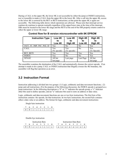
During a CALL to the upper 4K, the lower 4K is not accessible by either the jump or INDEX instructions,<br />
nor is it possible to make a CALL from the upper 4K to the lower 4K. After a call into the upper 4K, access<br />
to the lower 4K is restored by the RET or RETI instructions; at that point the upper 4K is again not<br />
accessible. The following table shows which operations are allowed. Please note that interrupt service<br />
routines do continue to operate normally regardless of the upper/lower state at the time of the interrupt.<br />
ISRs must be located in the lower 4K range and the RETI at the end of the ISR properly returns control to<br />
either the upper or lower 4K range.<br />
Control flow for B version microcontroller with 8K EPROM<br />
Instruction Type<br />
Low 4K<br />
to<br />
Low 4K<br />
Low 4K<br />
to<br />
High 4K<br />
High 4K<br />
to<br />
Low 4K<br />
High 4K<br />
to<br />
High 4K<br />
JACC, JC, JMP, JNC, JNZ, JZ Yes No No Yes<br />
CALL<br />
Yes<br />
(9x opcode)<br />
Yes<br />
(5x opcode)<br />
No<br />
RET, RETI Yes Yes Yes Yes<br />
INDEX Yes No No Yes<br />
XPAGE<br />
All but Last page Last Page All but<br />
last page<br />
last page<br />
Yes<br />
(5x Opcode)<br />
The assembler examines the destination of the CALL and automatically chooses the correct opcode. If an<br />
attempt is made to do a jump, CALL or INDEX instruction that illegally crosses the 4K boundary, the<br />
assembler will flag that operation as an error.<br />
3.2 Instruction Format<br />
Instruction addressing is divided into two groups: (1) Logic, arithmetic and data movement functions; (2)<br />
jump and call instructions. (For the purpose of the following discussion, the INDEX opcode is grouped as a<br />
jump instruction) In the following descriptions a “0” or “1” indicates the opcode group, a “c” indicates<br />
other bits used to define opcodes, and an “a” indicates bits used to store an address or data value.<br />
Logic, arithmetic and data movement functions are one or two byte instructions. The first byte of the<br />
instruction contains the opcode, for that instruction. In two byte instructions, the second byte contains<br />
either a data value or an address. The format for logic, arithmetic and data movement instructions:<br />
Single byte instruction<br />
7 6 5 4 3 2 1 0<br />
0 0 c c c c c c<br />
Double bye instruction<br />
Instruction Byte Instruction Data Byte<br />
7 6 5 4 3 2 1 0 7 6 5 4 3 2 1 0<br />
0 0 c c c c c c a a a a a a a a<br />
3