CYASM ASSEMBLER USER'S GUIDE VERSION 1.77
CYASM ASSEMBLER USER'S GUIDE VERSION 1.77
CYASM ASSEMBLER USER'S GUIDE VERSION 1.77

Create successful ePaper yourself
Turn your PDF publications into a flip-book with our unique Google optimized e-Paper software.
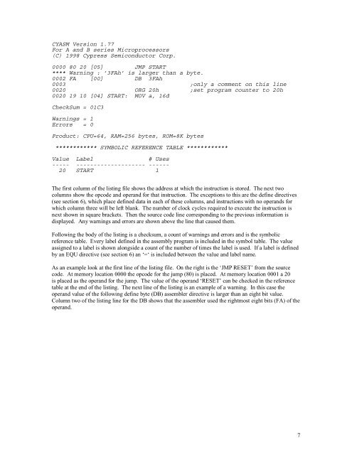
<strong>CYASM</strong> Version <strong>1.77</strong><br />
For A and B series Microprocessors<br />
(C) 1998 Cypress Semiconductor Corp.<br />
0000 80 20 [05] JMP START<br />
**** Warning : ’3FAh’ is larger than a byte.<br />
0002 FA<br />
0003<br />
[00] DB 3FAh<br />
;only a comment on this line<br />
0020 ORG 20h ;set program counter to 20h<br />
0020 19 10 [04] START: MOV a, 16d<br />
CheckSum = 01C3<br />
Warnings = 1<br />
Errors = 0<br />
Product: CPU=64, RAM=256 bytes, ROM=8K bytes<br />
************ SYMBOLIC REFERENCE TABLE ************<br />
Value Label<br />
# Uses<br />
----- -------------------- ------<br />
20 START 1<br />
The first column of the listing file shows the address at which the instruction is stored. The next two<br />
columns show the opcode and operand for that instruction. The exceptions to this are the define directives<br />
(see section 6), which place defined data in each of these columns, and instructions with no operands for<br />
which column three will be left blank. The number of clock cycles required to execute the instruction is<br />
next shown in square brackets. Then the source code line corresponding to the previous information is<br />
displayed. Any warnings and errors are shown above the line that caused them.<br />
Following the body of the listing is a checksum, a count of warnings and errors and is the symbolic<br />
reference table. Every label defined in the assembly program is included in the symbol table. The value<br />
assigned to a label is shown alongside a count of the number of times the label is used. If a label is defined<br />
by an EQU directive (see section 6) an ‘=‘ is included between the value and label name.<br />
As an example look at the first line of the listing file. On the right is the ‘JMP RESET’ from the source<br />
code. At memory location 0000 the opcode for the jump (80) is placed. At memory location 0001 a 20<br />
is placed as the operand for the jump. The value of the operand ‘RESET’ can be checked in the reference<br />
table at the end of the listing. The next line of the listing is an example of a warning. In this case the<br />
operand value of the following define byte (DB) assembler directive is larger than an eight bit value.<br />
Column two of the listing line for the DB shows that the assembler used the rightmost eight bits (FA) of the<br />
operand.<br />
7