Unichiller in Desktop Housing - HUBER
Unichiller in Desktop Housing - HUBER
Unichiller in Desktop Housing - HUBER

You also want an ePaper? Increase the reach of your titles
YUMPU automatically turns print PDFs into web optimized ePapers that Google loves.
Valid for:<br />
Operat<strong>in</strong>g manual<br />
<strong>Unichiller</strong> <strong>in</strong> <strong>Desktop</strong> Hous<strong>in</strong>g<br />
27.01.2012<br />
Valid for follow<strong>in</strong>g versions:<br />
plus, with natural refrigerant and<br />
models with heat<strong>in</strong>g<br />
M<strong>in</strong>ichiller, M<strong>in</strong>ichiller w<br />
<strong>Unichiller</strong> 006-MPC<br />
<strong>Unichiller</strong> 007-MPC, <strong>Unichiller</strong> 007w-MPC<br />
<strong>Unichiller</strong> 010-MPC<br />
<strong>Unichiller</strong> 012-MPC, <strong>Unichiller</strong> 012w-MPC<br />
<strong>Unichiller</strong> 015-MPC, <strong>Unichiller</strong> 015w-MPC<br />
<strong>Unichiller</strong> 022-MPC, <strong>Unichiller</strong> 022w-MPC<br />
<strong>Unichiller</strong> 023-MPC, <strong>Unichiller</strong> 023w-MPC<br />
<strong>Unichiller</strong> 025-MPC, <strong>Unichiller</strong> 025w-MPC<br />
<strong>Unichiller</strong> 006Tw-MPC, <strong>Unichiller</strong> 009Tw-MPC
Contents V1.7/01.12<br />
Foreword ............................................................................................................3<br />
Chapter 1: Safety ................................................................................................4<br />
Description of Safety and Information symbols ........................................................5<br />
Intended Use and General Safety Instructions..........................................................6<br />
Description .........................................................................................................7<br />
Duties of responsible person .................................................................................8<br />
Operator requirements..........................................................................................8<br />
Mach<strong>in</strong>e operator duties .......................................................................................8<br />
Work area...........................................................................................................8<br />
Safety Devices to DIN12876.................................................................................9<br />
Environmental Conditions.................................................................................... 10<br />
Location ........................................................................................................... 12<br />
Thermofluids ..................................................................................................... 13<br />
Chapter 2 : Electronics and operation ................................................................... 14<br />
Display and operation ......................................................................................... 15<br />
Chapter 3: Connect the mach<strong>in</strong>e, fill and prepare for the required application ............ 17<br />
Power connection .............................................................................................. 18<br />
Start up............................................................................................................ 19<br />
Connect<strong>in</strong>g an externally closed application (reactor).............................................. 20<br />
Switch<strong>in</strong>g on the temperature control unit ............................................................ 20<br />
Sett<strong>in</strong>g the over-temperature switch .................................................................... 21<br />
Enter<strong>in</strong>g a set po<strong>in</strong>t ............................................................................................ 21<br />
Start<strong>in</strong>g temperature control................................................................................ 21<br />
End<strong>in</strong>g temperature control ................................................................................. 21<br />
Fill<strong>in</strong>g and air purg<strong>in</strong>g an externally closed system ................................................. 22<br />
Dra<strong>in</strong><strong>in</strong>g the mach<strong>in</strong>e and an externally closed application....................................... 23<br />
Chang<strong>in</strong>g thermal fluid / <strong>in</strong>ternal clean<strong>in</strong>g.............................................................. 23<br />
Chapter 4: Interface and software update ............................................................. 24<br />
Data Communication.......................................................................................... 25<br />
Chapter 5: First aid for a fault condition................................................................ 29<br />
Display Error Messages....................................................................................... 30<br />
Alarms and Warn<strong>in</strong>gs ......................................................................................... 30<br />
Ma<strong>in</strong>tenance ..................................................................................................... 31<br />
Decontam<strong>in</strong>ation / Repair .................................................................................... 32<br />
Clean<strong>in</strong>g the surfaces ......................................................................................... 32<br />
Plug contacts .................................................................................................... 32<br />
Chapter 6: Tak<strong>in</strong>g the mach<strong>in</strong>e out of service........................................................ 33<br />
Decommission<strong>in</strong>g............................................................................................... 34<br />
Transport.......................................................................................................... 35<br />
Disposal ........................................................................................................... 35<br />
Appendix<br />
2
Foreword<br />
Dear Customer,<br />
The Huber team would like to thank you for order<strong>in</strong>g this product. You have made a<br />
good choice. We thank you for your trust!<br />
Please read and understand the <strong>in</strong>struction manual thoroughly before operat<strong>in</strong>g the unit.<br />
All <strong>in</strong>structions and safety <strong>in</strong>formation must be complied with.<br />
Please read this manual before transport<strong>in</strong>g, commission<strong>in</strong>g, operat<strong>in</strong>g, ma<strong>in</strong>ta<strong>in</strong><strong>in</strong>g,<br />
repair<strong>in</strong>g, stor<strong>in</strong>g or dispos<strong>in</strong>g of this unit.<br />
Failure to comply with the <strong>in</strong>structions with<strong>in</strong> this manual may <strong>in</strong>validate any warranty<br />
for this unit.<br />
3
Chapter 1: Safety<br />
In this chapter is to be found the follow<strong>in</strong>g sections:<br />
4<br />
- Description of safety and <strong>in</strong>formation symbols<br />
- Intended use and General Safety Instructions<br />
- Description<br />
- Duties of the responsible person<br />
- Operator requirements<br />
- Mach<strong>in</strong>e operator duties<br />
- Work area<br />
- Safety Devices to DIN 12876 (applicable for units with heat<strong>in</strong>g)<br />
- Environmental conditions<br />
- Operat<strong>in</strong>g conditions<br />
- Location<br />
- Thermal fluids
Description of Safety and Information symbols<br />
Safety <strong>in</strong>formation is shown with a pictogram and keyword.<br />
The keyword <strong>in</strong>dicates the level of the correspond<strong>in</strong>g danger.<br />
Danger!<br />
Warn<strong>in</strong>g!<br />
Caution!<br />
Information!<br />
Requirement!<br />
Immediate risk to the life and health of<br />
personnel (Serious <strong>in</strong>jury or death).<br />
Possible risk to the life and health of<br />
personnel (Serious <strong>in</strong>jury or death).<br />
Possible dangerous situation (possible <strong>in</strong>jury<br />
to personnel or damage to property).<br />
User-tips and other useful <strong>in</strong>formation.<br />
Requirement to carry out a specific<br />
method, or action, for safe mach<strong>in</strong>e<br />
operation.<br />
5
Intended Use and General Safety Instructions<br />
Danger!<br />
Non-<strong>in</strong>tended use can result <strong>in</strong> considerable personal <strong>in</strong>juries and material damage.<br />
No third persons are authorized to make any changes to the mach<strong>in</strong>e. The device<br />
declaration becomes void, if any modification is carried out without manufacturers<br />
consent. Only personnel tra<strong>in</strong>ed by the manufacturer may carry out modifications,<br />
repairs or ma<strong>in</strong>tenance work.<br />
The follow<strong>in</strong>g must be observed:<br />
Always use the mach<strong>in</strong>e <strong>in</strong> a perfect work<strong>in</strong>g condition!<br />
Only expert personnel may <strong>in</strong>itially start-up and repair the device!<br />
Do not bypass, bridge-over, dismantle or switch off the safety mechanisms!<br />
The manufacturer is not liable for damages caused by technical changes<br />
to the temperature control device, <strong>in</strong>appropriate handl<strong>in</strong>g and / or use of the<br />
temperature control device without regard to the operat<strong>in</strong>g <strong>in</strong>structions.<br />
The temperature control device is manufactured for commercial use only and may only<br />
be used to ma<strong>in</strong>ta<strong>in</strong> the temperature with<strong>in</strong> the <strong>in</strong>ternal bath (does not apply for chillers)<br />
and to ma<strong>in</strong>ta<strong>in</strong> the temperature of reactors or other professionally expedient objects <strong>in</strong><br />
laboratories and <strong>in</strong>dustry. Suitable thermal fluids are used throughout the entire system.<br />
The refrigerat<strong>in</strong>g or heat<strong>in</strong>g capacity is provided at the pump connections and <strong>in</strong> the<br />
bath itself (does not apply for chillers). The technical specifications of the temperature<br />
control device are determ<strong>in</strong>ed <strong>in</strong> the data sheet. Operation must be prepared and carried<br />
out accord<strong>in</strong>g to the operat<strong>in</strong>g <strong>in</strong>structions. Any non-observance of the operat<strong>in</strong>g<br />
<strong>in</strong>structions is considered as non-<strong>in</strong>tended use.<br />
The temperature control device corresponds to the state-of-the-art and the recognized<br />
safety-related regulations. Safety devices are built <strong>in</strong>to your temperature control device.<br />
The device is NOT approved for use as a medical product!<br />
This temperature control unit is NOT built as explosion-proof and is NOT<br />
suitable for use <strong>in</strong> "ATEX" areas!<br />
Foreseeable non-<strong>in</strong>tended use:<br />
6<br />
- Activate the brakes for mach<strong>in</strong>es with rollers or roller support.
Description<br />
Chillers are temperature control devices that ideally are used for carry<strong>in</strong>g away of<br />
process heat and as economic alternative for cool<strong>in</strong>g water (dr<strong>in</strong>k<strong>in</strong>g water) i.e. for a<br />
reflux condenser, condensers, tools,…<br />
Due to high refrigeration performance a very short cool<strong>in</strong>g time can be achieved.<br />
A pump is responsible for a good circulation of the thermal fluid.<br />
For Chillers with a pump that can build pressure up to 2,5 bar, supply l<strong>in</strong>e pressure can<br />
be set by means of a VPC-Bypass and thus can be adapted for the required application.<br />
The pressure of the supply l<strong>in</strong>e is <strong>in</strong>dicated via a manometer display.<br />
Temperatures can be easily red via the LED-display screen.<br />
An easy keypad (set-po<strong>in</strong>t, arrow up and arrow down key) is used to set a set-po<strong>in</strong>t.<br />
Thermostats uses an over-temperature protection <strong>in</strong> accordance with DIN EN 61010-2-<br />
010, which is <strong>in</strong>dependent of the actual control circuits (only valid for units with<br />
heat<strong>in</strong>g)<br />
7
Duties of responsible person<br />
The operat<strong>in</strong>g <strong>in</strong>struction is to be kept easily accessible and <strong>in</strong> immediate vic<strong>in</strong>ity of the<br />
unit. Only suitably qualified personnel should operate this unit. Personnel should be<br />
properly tra<strong>in</strong>ed before operat<strong>in</strong>g the unit. Make sure that the operators have read and<br />
understood the <strong>in</strong>struction manual. Supply appropriate Personal Protective Equipment as<br />
required.<br />
Operator requirements<br />
Only authorised personnel should operate this unit. Personnel should be properly tra<strong>in</strong>ed<br />
before operat<strong>in</strong>g the unit. The m<strong>in</strong>imum age for operators is 18 years. Personnel under<br />
18 years should only operate the unit under the direct supervision of qualified<br />
personnel. The operator is responsible for third parties with<strong>in</strong> the work<strong>in</strong>g area.<br />
Mach<strong>in</strong>e operator duties<br />
Make sure that the operators have read and understood the <strong>in</strong>struction manual. Please<br />
observe the safety <strong>in</strong>structions. Appropriate Personal Protective Equipment (e.g. safety<br />
goggles, safety gloves) should be worn when operat<strong>in</strong>g the unit.<br />
Work area<br />
Work area is def<strong>in</strong>ed as the area <strong>in</strong> front of the mach<strong>in</strong>es control panel. Work area is<br />
determ<strong>in</strong>ed by the peripheral equipment connected by the operator.<br />
It is the customer’s responsibility to ensure a clear, safe work<strong>in</strong>g area around the<br />
temperature control unit. The arrangement of the work area should be made after<br />
consider<strong>in</strong>g access to, and risk assessment of, the area and application.<br />
8
Safety Devices to DIN12876<br />
- Low level switch<br />
- Adjustable over-temperature switch (also valid for units with heat<strong>in</strong>g)<br />
Classification of Laboratory Thermostats and Baths<br />
Classification Thermal Fluid Technical requirement Designation d<br />
I non-flammable a Over-temperature cut-off c NFL<br />
II Adjustable over-temperature cut-off<br />
flammable b FL<br />
III Adjustable over-temperature cut-off<br />
and extra low-level switch<br />
a Normally water; other fluids only when they are non-flammable <strong>in</strong> the event of a s<strong>in</strong>gle<br />
failure.<br />
b<br />
The thermal fluid must have a flame po<strong>in</strong>t ≥ 65 °C, this means that ethanol can only<br />
be used under constant supervision.<br />
c<br />
The over-temperature protection can for example be provided by a fluid sensor or<br />
a suitable over temperature switch.<br />
d Determ<strong>in</strong>ed by the manufacturer.<br />
Temperature control units with heat<strong>in</strong>g (marked by an "-H" <strong>in</strong> the name) are designated<br />
as class III FL.<br />
Temperature control units without heat<strong>in</strong>g are designated as class I NFL.<br />
Mechanical Over-temperature Switch<br />
This temperature control unit is equipped with a mechanical over-temperature switch.<br />
For sett<strong>in</strong>g the over-temperature protection refer to chapter sett<strong>in</strong>g the overtemperature<br />
switch.<br />
9
Environmental Conditions<br />
This unit, and operations, will comply with DIN EN 61010-1:2001, only when it is<br />
located <strong>in</strong> suitable environmental conditions.<br />
10<br />
- for <strong>in</strong>door use only;<br />
- <strong>in</strong>stallation site ≤ 2000 m altitude;<br />
- <strong>in</strong>stalled on a level, even, non flammable surface;<br />
- ma<strong>in</strong>ta<strong>in</strong> a clearance above and around the unit of 10 cm for water-cooled units,<br />
and 20cm for air-cooled units, to allow air to circulate around the unit;<br />
- for ambient temperature conditions please refer to the technical data sheet;<br />
rema<strong>in</strong><strong>in</strong>g with<strong>in</strong> these ambient conditions is imperative <strong>in</strong> ensur<strong>in</strong>g accurate<br />
operation;<br />
- maximum relative humidity of 80% up to 32°C, decreas<strong>in</strong>g l<strong>in</strong>early to 50%<br />
relative humidity at 40°C<br />
- use only as long a power cord as necessary;<br />
- the unit should be located so as not to restrict access to the ma<strong>in</strong>s power<br />
switch;<br />
- ma<strong>in</strong>s voltage should be ±10% of the rated value;<br />
- avoid voltage spikes;<br />
- transient voltage surges as they occur normally <strong>in</strong> the supply grid;<br />
- clean rat<strong>in</strong>g 2;<br />
- overvoltage category II
Operat<strong>in</strong>g conditions<br />
Please make sure that the application and system performance is dependent upon the<br />
temperature range, viscosity, and flow rate of the thermal fluid:<br />
- Please ensure that the power supply connections are correctly dimensioned.<br />
- The temperature control device should be located so, that sufficient fresh air<br />
is available even when work<strong>in</strong>g with water cooled units.<br />
- Please note that hose connections should be compatible with the thermal<br />
fluid used and the work<strong>in</strong>g conditions.<br />
- When choos<strong>in</strong>g the thermal fluid, not only m<strong>in</strong>imal and maximum<br />
temperatures have to be complied with but also have to be suitable regard<strong>in</strong>g<br />
burn po<strong>in</strong>t, viscosity and / or freez<strong>in</strong>g. Furthermore the thermal fluid has to be<br />
compatible with all the materials used <strong>in</strong> the unit.<br />
- Pressure changes with the length of hoses (keep as short as possible).<br />
Choose as large a diameter of hoses as possible (the width of the pump<br />
connections are considered as a po<strong>in</strong>t of reference) and may negatively affect<br />
temperature control results. Flow restrictions may occur if a too narrow<br />
connector is selected for corrugated hoses.<br />
- The use of unsuitable hoses or hose connections may cause thermal and<br />
toxic <strong>in</strong>jury to personal and environment. Temperature control hoses and their<br />
connections have to be <strong>in</strong>sulated / secured aga<strong>in</strong>st contact / mechanical<br />
damage.<br />
- Non-suitable thermal fluids can negatively affect temperature control and be<br />
the cause of negative temperature results and damages. Therefore only use<br />
the thermal fluids recommended by the manufacturer and only <strong>in</strong> the <strong>in</strong>tended<br />
temperature and pressure range. The application should be located on<br />
approximately the same level or lower than the temperature control device, if<br />
temperature control is to be carried out near to the boil<strong>in</strong>g temperature of the<br />
thermal fluid. The thermal fluid should have room temperature when fill<strong>in</strong>g.<br />
Fill <strong>in</strong> the thermal fluid slowly, carefully and steadily. At the same time make<br />
sure that no thermal fluid overflows (back pressure); it is thereby necessary<br />
to wear personal protective equipment, e.g. safety goggles, thermally and<br />
chemically resistant gloves, etc.<br />
- In the case of pressure-sensitive applications, e.g. glass reactors, observe the<br />
maximum <strong>in</strong>let pressure of the temperature control device for cross section<br />
reduction or shut-off (see data sheet). Take suitable precautions (e.g.<br />
pressure limitation for temperature control devices with pressure control,<br />
bypass).<br />
- In order to avoid danger of overpressure <strong>in</strong> the system, which could damage<br />
the temperature control device or the application, the thermal fluid must<br />
always be adapted at room temperature before turn<strong>in</strong>g off and a possibly<br />
available shut-off valve must be left open (pressure compensation).<br />
- Do not k<strong>in</strong>k the hoses.<br />
- Check hoses <strong>in</strong> regular <strong>in</strong>tervals for material fatigue (e.g. cracks).<br />
11
With water cooled units please pay special attention to the maximum operat<strong>in</strong>g<br />
temperature and differential pressure requirements for the cool<strong>in</strong>g water. Therefore<br />
please refer to the technical data sheet.<br />
Danger!<br />
If the cool<strong>in</strong>g water conta<strong>in</strong>s high levels of m<strong>in</strong>erals, e.g. chloride, bromide then suitable<br />
water treatment chemicals should be used. Use only recommended materials to<br />
ma<strong>in</strong>ta<strong>in</strong> the unit warranty. Further <strong>in</strong>formation on corrosion, (appearance and<br />
avoidance) can be found on our website www.huber-onl<strong>in</strong>e.com under "Download /<br />
Safety data sheets thermofluids / Characteristics of water".<br />
Please refer to the sections on Intended use and general safety <strong>in</strong>structions.<br />
Location<br />
12<br />
Caution!<br />
- Transport the unit upright.<br />
- The unit should be mounted <strong>in</strong> an upright and secure position, on a solid, stable<br />
surface.<br />
- Place on a non flammable surface.<br />
- Keep the area around the unit clean, to avoid slip and trip hazards.<br />
- Set the brakes on the castors once the unit is <strong>in</strong> position.<br />
- Place suitable absorbent material under the unit to catch any condensate and<br />
thermal fluid spills.<br />
- Any spillage of thermal fluid should be immediately cleaned up.<br />
- For large units, check the weight / load capacity for the floor<strong>in</strong>g
Thermofluids<br />
We recommend the thermal fluid shown <strong>in</strong> our catalogue. The name of a thermal fluid is<br />
derived from the work<strong>in</strong>g temperature range and the viscosity at 25 °C.<br />
Examples of thermal fluids <strong>in</strong> our catalogue:<br />
M40.165.10:<br />
� Lower work<strong>in</strong>g limit -40 °C<br />
� Upper work<strong>in</strong>g limit 165 °C<br />
� Viscosity at 25 °C: 10 mm 2 /s<br />
The data sheet for the thermal fluid used is of utmost importance, and must be read<br />
before use. This data sheet should be followed.<br />
� Please note the classification of your mach<strong>in</strong>e accord<strong>in</strong>g to DIN 12876<br />
� The chosen thermal fluid must be compatible with sta<strong>in</strong>less steel 1.4301 (V2A)<br />
and FKM!<br />
� The maximum viscosity of the thermal fluid may not exceed 50 mm²/s at the<br />
lowest temperature reached!<br />
� The maximum density of the thermal fluid may not exceed 1kg / dm³<br />
� For chillers we recommend as thermal fluid a mixture of water and glycol (a<br />
mixture is recommended that permits a temperature down to -25°C).<br />
Information on water quality can be found on our website (www.huberonl<strong>in</strong>e.com)<br />
under "Download / Safety data sheets thermofluids / Characteristics<br />
of water".<br />
13
Chapter 2 : Electronics and operation<br />
The follow<strong>in</strong>g sections are to be found <strong>in</strong> this chapter:<br />
14<br />
- Information displays and operation
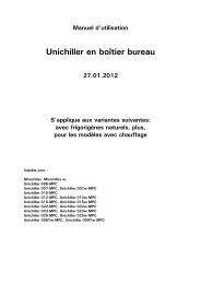
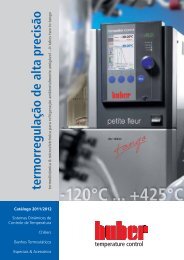
Display and operation<br />
Display<br />
LEDs<br />
Sett<strong>in</strong>g keys Set-Po<strong>in</strong>t Key On / Off<br />
As a standard, <strong>in</strong>ternal temperature (e.g. temperature of the bath for thermoregulation<br />
units and outlet temperature for chillers) is displayed. By press<strong>in</strong>g the SET-Key a<br />
switchover to the actual set-po<strong>in</strong>t temperature takes place. Keep<strong>in</strong>g the SET-Key<br />
pressed, you may change the set-po<strong>in</strong>t. Via the two arrow-keys you may select the setpo<strong>in</strong>t.<br />
To START / STOP thermoregulation press the ON / OFF key. LEDs (Heat<strong>in</strong>g,<br />
Cool<strong>in</strong>g and Pump) give <strong>in</strong>formation on the current operat<strong>in</strong>g status.<br />
RS232 <strong>in</strong>terface (optional):<br />
The temperature control device comes with an RS232 digital <strong>in</strong>terface as an option.<br />
Detailed <strong>in</strong>formation can be found <strong>in</strong> chapter 4 of this manual.<br />
15
Menu functions<br />
The device conta<strong>in</strong>s a menu with functions. In this menue you can undertake the<br />
sett<strong>in</strong>gs of the AutoMode.<br />
AutoMode:<br />
AutoMode (also called power failure automatic) ensures that after switch<strong>in</strong>g off of the<br />
unit (<strong>in</strong>tentional or un<strong>in</strong>tentional), the sett<strong>in</strong>gs previously set (before power loss) will<br />
automatically be taken over. Proceed as follow if you want to set the AutoMode:<br />
Menu po<strong>in</strong>ts<br />
ADR = no function<br />
PA = service menu for Huber service personnel<br />
C40 = AutoMode<br />
- Simultaneously press down the and keys> 3 s.<br />
- Press the key to enter the menu po<strong>in</strong>t “C40”.<br />
- In the “C40” menu, press the SET key. Hold this key down while simultaneously<br />
press<strong>in</strong>g the or key. The display will change from “0” (AutoMode activated) to<br />
“I” (AutoMode de-activated). After reach<strong>in</strong>g the desired sett<strong>in</strong>g, release the SET key.<br />
- After a few seconds, the menu will be automatically exited and the chosen sett<strong>in</strong>gs<br />
will be saved. To leave the menu more rapidly, simultaneously press the and ><br />
1 s.<br />
16
Chapter 3: Connect the mach<strong>in</strong>e, fill and prepare for the<br />
required application<br />
- Power connection<br />
- Start up<br />
- Connect<strong>in</strong>g an externally closed application<br />
- Switch<strong>in</strong>g on the temperature control unit<br />
- Sett<strong>in</strong>g the over-temperature switch<br />
- Sett<strong>in</strong>g set po<strong>in</strong>t limits<br />
- Enter<strong>in</strong>g a set po<strong>in</strong>t<br />
- Start<strong>in</strong>g temperature control<br />
- End<strong>in</strong>g temperature control<br />
- Fill<strong>in</strong>g and air purg<strong>in</strong>g an externally closed system<br />
- Dra<strong>in</strong><strong>in</strong>g an externally closed application<br />
- Thermofluid change / <strong>in</strong>ternal clean<strong>in</strong>g<br />
17
Power connection<br />
. Danger!<br />
Check to make sure that the l<strong>in</strong>e voltage matches the supply voltage specified on the<br />
identification plate or data sheet.<br />
We disclaim all liability for damage caused by <strong>in</strong>correct l<strong>in</strong>e voltages!<br />
Safety <strong>in</strong>structions<br />
18<br />
Danger!<br />
Caution!<br />
Danger!<br />
Only connect the unit to a power socket<br />
with earth<strong>in</strong>g contact (PE – protective earth)!<br />
Do not move the unit from its location while<br />
it is runn<strong>in</strong>g.<br />
Never operate equipment with damaged<br />
ma<strong>in</strong>s power cables.
Start up<br />
General<br />
All models must be moved and <strong>in</strong>stalled <strong>in</strong> an upright position. Provide for a stable<br />
<strong>in</strong>stallation and make sure that the thermostat cannot tilt. Ensure that sufficient fresh<br />
air is available for the circulation pump and compressors at the <strong>in</strong>stallation site. The<br />
warm exhaust air must be able to escape unh<strong>in</strong>dered upwards.<br />
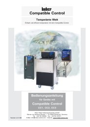
Water-cool<strong>in</strong>g (valid for units with water cool<strong>in</strong>g)<br />
A cool<strong>in</strong>g water controller is used <strong>in</strong> Huber temper<strong>in</strong>g devices with water cool<strong>in</strong>g, <strong>in</strong><br />
order to reduce the cool<strong>in</strong>g water consumption. This only allows as much cool<strong>in</strong>g water<br />
to flow as is required by the current load situation of the temper<strong>in</strong>g device. Only little<br />
cool<strong>in</strong>g water is consumed, if the required refrigerat<strong>in</strong>g capacity is low. No cool<strong>in</strong>g<br />
water flows <strong>in</strong> the OFF state. Only use pressure-resistant hoses <strong>in</strong> the cool<strong>in</strong>g water<br />
circuit.<br />
Connection diagram:<br />
water <strong>in</strong>let water outlet dra<strong>in</strong><strong>in</strong>g / water<br />
Caution!<br />
Depend<strong>in</strong>g upon mode of operation and available cool<strong>in</strong>g water pressure, a cool<strong>in</strong>g<br />
water pressure of > 2 bar can build up <strong>in</strong> the cool<strong>in</strong>g water supply l<strong>in</strong>e. In order to<br />
avoid flood<strong>in</strong>g of the premises, check the leak tightness and quality of the hoses, hose<br />
connections <strong>in</strong> regular <strong>in</strong>tervals, and if necessary take appropriate measures<br />
(Replacement). Close down the cool<strong>in</strong>g water supply to the temper<strong>in</strong>g device even<br />
dur<strong>in</strong>g shorter shutdowns (e.g. over night).<br />
Re<strong>in</strong>forced hoses must be used for <strong>in</strong>creased safety requirements.<br />
Preparation of devices with water-cool<strong>in</strong>g:<br />
Establish the hose connections for the cool<strong>in</strong>g water. The filter screen has to be<br />
<strong>in</strong>serted <strong>in</strong>to the cool<strong>in</strong>g water <strong>in</strong>let. Please <strong>in</strong>fer the position of the cool<strong>in</strong>g water<br />
connections from the connection diagram <strong>in</strong> the appendix. Cool<strong>in</strong>g water connectors<br />
Dra<strong>in</strong>age with seal cap held closed and /or close. Open all stop valves. Please <strong>in</strong>fer the<br />
m<strong>in</strong>imum / maximum differential pressure <strong>in</strong> the cool<strong>in</strong>g water circuit and the<br />
recommended cool<strong>in</strong>g water <strong>in</strong>let temperature from the data sheet.<br />
Information on water quality can be found on our website (www.huber-onl<strong>in</strong>e.com)<br />
under "Download / Safety data sheets thermofluids / Characteristics of water".<br />
19
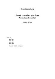
Connect<strong>in</strong>g an externally closed application (reactor)<br />
Remove the thread covers from the unit´s circulation flow (1) and circulation return (2).<br />
Make sure that the hose material is compatible with the thermal fluid and temperature<br />
range be<strong>in</strong>g used. In order that the application can be driven correctly, and that no air<br />
bubbles rema<strong>in</strong> <strong>in</strong> the system, ensure that the unit´s circulation flow (1) is attached to<br />
the lowest connection on the application, and the unit´s circulation return (2) is<br />
attached to the highest connection on the application.<br />
Please note the mark<strong>in</strong>gs for the hose connections on the hous<strong>in</strong>g<br />
Switch<strong>in</strong>g on the temperature control unit<br />
The temperature control unit can be switched on us<strong>in</strong>g the ma<strong>in</strong>s switch (36).<br />
Circulation and thermoregulation are switched off.<br />
20<br />
2<br />
1<br />
Mark<strong>in</strong>gs on the<br />
temperature control<br />
device
Sett<strong>in</strong>g the over-temperature switch<br />
(also valid for chillers with heat<strong>in</strong>g)<br />
General Information<br />
The over-temperature switch is an <strong>in</strong>dependent function of the temperature control unit.<br />
The over-temperature tripp<strong>in</strong>g value of the heat<strong>in</strong>g and circulation may be set by us<strong>in</strong>g a<br />
tool (e.g. screwdriver). The constant monitor<strong>in</strong>g of the <strong>in</strong>ternal temperature provides<br />
safety for the connected application. It should be set immediately after hav<strong>in</strong>g filled the<br />
device with the thermal fluid.<br />
Warn<strong>in</strong>g!<br />
The over-temperature switch should be tested at least monthly, and after chang<strong>in</strong>g the<br />
thermal fluid.<br />
The over-temperature switch should be set at least 25 K below the flame po<strong>in</strong>t of the<br />
thermal fluid.<br />
When received, the cut-off will be set to 35 °C.<br />
If the temperature of the thermal fluid is higher then this value when filled the mach<strong>in</strong>e<br />
switches off (STOP to DIN EN 61010) and an alarm will be given after a short time.<br />
After remov<strong>in</strong>g cause of the error (e.g. by us<strong>in</strong>g a thermal fluid with a higher burn<strong>in</strong>g<br />
po<strong>in</strong>t and the correct sett<strong>in</strong>g of the over-temperature protection) start the device aga<strong>in</strong>.<br />
Enter<strong>in</strong>g a set po<strong>in</strong>t<br />
You can enter a set po<strong>in</strong>t by press<strong>in</strong>g the SET-Key and ARROW UP or ARROW DOWN<br />
Key simultaneously.<br />
Start<strong>in</strong>g temperature control<br />
Temperature control and circulation may be started / stopped via the ON / OFF key.<br />
Any air trapped <strong>in</strong> the system may be vented via the bath / sight glass (if available) or<br />
via the open<strong>in</strong>g at the fill<strong>in</strong>g nozzle with external closed applications. After fill<strong>in</strong>g and<br />
fully air purg<strong>in</strong>g the temperature control unit can be started.<br />
End<strong>in</strong>g temperature control<br />
The temperature control can be ended at any time by press<strong>in</strong>g the ON / OFF key.<br />
21
Fill<strong>in</strong>g and air purg<strong>in</strong>g an externally closed system<br />
22<br />
Caution!<br />
- For additional protection of a fragile application (e.g. glass reactor), chillers with<br />
pumps, which are able to build pressures up to 3 bar, are equipped with a VPC<br />
Bypass. Outlet pressure can be set via a valve which is next to the <strong>in</strong>let nozzles<br />
(Check the manometer display on the front of the chiller). Before operat<strong>in</strong>g the<br />
mach<strong>in</strong>e, turn the valve to the left endstop (anticlockwise). Then on start<strong>in</strong>g the<br />
pump, the smallest possible pressure will be produced.<br />
- Fill to the unit to the m<strong>in</strong>imum level necessary.<br />
- Please refer to local regulations and <strong>in</strong>ternal procedures.<br />
- When fill<strong>in</strong>g the unit, extra precautions such as earth<strong>in</strong>g the expansion vessel,<br />
fluid conta<strong>in</strong>er funnel and application may be necessary.<br />
- Personal Protection Equipment (PPE) should be worn as required by the fluid<br />
MSDS sheets, and local regulation.<br />
- Please note the temperature of the thermal fluid. The fluid should be left a room<br />
temperature for a few m<strong>in</strong>utes before dra<strong>in</strong><strong>in</strong>g.<br />
Warn<strong>in</strong>g!<br />
Overflow<strong>in</strong>g thermal fluid will create a film on surfaces, which should be cleaned up and<br />
properly disposed of as soon as possible <strong>in</strong> accordance with the MSDS <strong>in</strong>formation. If<br />
thermal fluid is spilled over the unit, the unit should be immediately turned off, and<br />
Huber-tra<strong>in</strong>ed personnel consulted.<br />
Failure to observe the above precautions may mean that the unit will not comply with<br />
all of the requirements of DIN EN 61010-2-010.<br />
Fill<strong>in</strong>g and air purg<strong>in</strong>g<br />
- Lift the bath cover / lid from the bath / <strong>in</strong>let connections<br />
- Carefully pour a suitable thermal fluid <strong>in</strong>to the expansion vessel, fill<strong>in</strong>g port (17)<br />
with help of appropriate accessories such as a funnel and / or beaker. The<br />
thermal fluid flows via the expansion vessel (18) <strong>in</strong>to the mach<strong>in</strong>e, then through<br />
the hoses <strong>in</strong>to the external application.<br />
- Then start the temperature control device and fill <strong>in</strong> thermal fluid as required.<br />
- The fill<strong>in</strong>g process / air purg<strong>in</strong>g process is f<strong>in</strong>ished when the fluid level is stable<br />
and the bath is filled sufficiently. Fill only half of the sight glass with thermal<br />
fluid. Start temperature control and fill <strong>in</strong> thermal fluid as required.<br />
- Note the volume change of the thermal fluid (especially with oils) <strong>in</strong> connection<br />
with the operat<strong>in</strong>g temperature. At the lowest temperature required, the fluid<br />
must be above the m<strong>in</strong>imum mark <strong>in</strong> the sight glass, and it must not overflow at<br />
the highest temperature required. In case of over fill<strong>in</strong>g, dra<strong>in</strong> off the excess fluid<br />
<strong>in</strong>to a suitable conta<strong>in</strong>er via the dra<strong>in</strong> (8).<br />
- With the help of the bypass on the mach<strong>in</strong>e top, set the permissible pressure<br />
that your application can carry (direction +). the pressure is displayed on the<br />
manometer.
Dra<strong>in</strong><strong>in</strong>g the mach<strong>in</strong>e and an externally closed application<br />
General<br />
- Before dra<strong>in</strong><strong>in</strong>g the unit, the thermal fluid should be at ambient temperature<br />
(approx. 20 °C). If not, let the mach<strong>in</strong>e run with a set-po<strong>in</strong>t of approx. 20 °C for<br />
a few m<strong>in</strong>utes until the thermal fluid is at a safe temperature.<br />
- Connect one end of a suitable dra<strong>in</strong> hose to the dra<strong>in</strong> of the unit (8), and place<br />
the other end <strong>in</strong>to a suitable conta<strong>in</strong>er (make sure the hose and conta<strong>in</strong>er<br />
materials are compatible with the thermal fluid be<strong>in</strong>g used.<br />
Dra<strong>in</strong><strong>in</strong>g<br />
- Open the dra<strong>in</strong> valve (4) if available.<br />
- The thermal fluid should flow through the pump case, and dra<strong>in</strong> port <strong>in</strong>to the<br />
conta<strong>in</strong>er.<br />
- Disconnect the hose from the unit’s circulation flow (1).<br />
- Disconnect the hose from the unit´s circulation return (2).<br />
- Leave the temperature control device open to dry out for some time (without<br />
seal<strong>in</strong>g caps and open dra<strong>in</strong> valve (4).<br />
Chang<strong>in</strong>g thermal fluid / <strong>in</strong>ternal clean<strong>in</strong>g<br />
- After empty<strong>in</strong>g the unit as described <strong>in</strong> the chapter Dra<strong>in</strong><strong>in</strong>g the mach<strong>in</strong>e and an<br />
externally closed application depend<strong>in</strong>g on the thermal fluid, it is possible that<br />
remnants of the oil rema<strong>in</strong> <strong>in</strong> the mach<strong>in</strong>e.<br />
- Connect a short hose between the circulation return (2) and circulation flow (1)<br />
of the unit.<br />
- When hav<strong>in</strong>g used silicon oils as thermal fluid, use a suitable solvent (e.g.<br />
Mucasol) to clean the <strong>in</strong>ternal components such as pump hous<strong>in</strong>g, reservoir, etc.<br />
Depend<strong>in</strong>g on the amount of contam<strong>in</strong>ation, it may be necessary to dra<strong>in</strong> the<br />
solvent off, and repeat the procedure a number of times with clean solvent.<br />
- Afterwards, leave the temperature control device stand for some time (open all<br />
dra<strong>in</strong> valves and have the connections opened).<br />
23
Chapter 4: Interface and software update<br />
The follow<strong>in</strong>g sections are to be found <strong>in</strong> this chapter:<br />
24<br />
- Data Communication
Data Communication<br />
Transmission format:<br />
Baud rate 9600<br />
Process asynchronous<br />
Star bit 1<br />
Data bits 8<br />
Parity none<br />
Stop bit 1<br />
Handshake no<br />
Parameters are programmed and can not be changed!<br />
Time behaviour (tim<strong>in</strong>g)<br />
The software protocols shall have to be structured <strong>in</strong> such a way that very simple<br />
tim<strong>in</strong>g rules can be applied:<br />
The data flow with<strong>in</strong> a command should not be <strong>in</strong>terrupted. Pauses of more than 100<br />
ms between the characters of a command will cause the receiver to abort the command<br />
<strong>in</strong> the process of reception. The protocols have been set up <strong>in</strong> such a way that an<br />
„echo“ can always be received. If the echo has been received, the next command can<br />
be transmitted immediately.<br />
The typical response time is below 300 ms.<br />
If no echo is used, it is recommended to wait for 1 s between two commands.<br />
The LAI command group<br />
A number of bus-compatible commands are available under the protocol designation of<br />
LAI. The „General guidel<strong>in</strong>es“ of the software protocols are applicable.<br />
In addition, there are the follow<strong>in</strong>g special features:<br />
LAI command structure<br />
A LAI command is structured as follows:<br />
„[mssilld...dpp\r„.<br />
with:<br />
[ start character 5Bh 1 byte<br />
m transmitter identifier M (4Dh) for master<br />
or S (53h) for slave 1 byte<br />
ss slave address 01 2 bytes<br />
i identifier of the data group 1 byte<br />
ll length of the data field 2 bytes<br />
d...d data group 0…50 bytes<br />
pp check sum 2 bytes<br />
\r rogue <strong>in</strong>dicator CR (0Dh) 1 byte<br />
The transmitter identifier <strong>in</strong>dicates the direction of the data traffic. All characters <strong>in</strong><br />
front of the check sum are referred to as data field. The data group are the characters<br />
after the seventh byte up to the check sum. The actual data are conta<strong>in</strong>ed <strong>in</strong> the data<br />
group. The significance of the data is determ<strong>in</strong>ed by the identifier and the transmitter<br />
identifier. Below the commands will be referred to accord<strong>in</strong>g to the identifier of the data<br />
group.<br />
25
In order to <strong>in</strong>crease the data safety, a check sum is transmitted.<br />
The check sum is the 1 byte sum of all hex values from the start character to the last<br />
character <strong>in</strong> front of the check sum.<br />
Example: The Master sends : „[M01V07C6\r„<br />
ASCII Hex Mean<strong>in</strong>g<br />
1.Byte [ 5Bh Start signal<br />
2.Byte M 4Dh Transmitter identification<br />
M= Master<br />
3.Byte 0 30h Slave address<br />
4.Byte 1 31h Slave address<br />
5.Byte V 56h Identifier data group<br />
6.Byte 0 30h Length of the data field (0)<br />
7.Byte 7 37h Length of the data field (7)<br />
8.Byte C 43h Check sum<br />
9.Byte 6 36h Check sum<br />
10.Byte \r 0Dh End-character CR<br />
A checksum is built up from the bytes <strong>in</strong> the data field.<br />
5Bh+4Dh+30h+31h+56h+30h+37h = 1C6h--> 1 Byte Summe = C6h<br />
In order to be able to query variables without changes, it is possible to set the „*“<br />
character <strong>in</strong>stead of a variable <strong>in</strong> the master command. The receiver, thus the<br />
thermostat, will not change the variable at this position. In this case, all positions which<br />
the variable takes, have to be rendered with the „*“ character. In the examples, the<br />
thermostat is always addressed with the identifier (device address) 01.<br />
´V´ Verify - Command<br />
Provided to check the presence of a slave.<br />
Master query:<br />
„[M01V07C6\r“ The master queries whether the slave 01 is connected to the bus.<br />
Slave answer:<br />
„[S01V0EMINI CCAD\r“ Slave 01 (temperature control device) is connected. The device<br />
is a MINI CC (Example). The slave command has the „MINI CC“ data group, which is 7<br />
bytes long. These 7 bytes plus the 7 bytes <strong>in</strong> front of the data group produce a data<br />
field length of 14 bytes = 0Eh byte.<br />
26
´G´ General Command<br />
This command transmits the most important temperatures and the status <strong>in</strong>formation. A<br />
modified set po<strong>in</strong>t value is not saved to the permanent memory, i.e. this value is lost<br />
when the ma<strong>in</strong>s is switched off.<br />
Master query: „[M01G0Dsattttpp\r“<br />
s = Control mode:<br />
´C´ = Circulation, switch on the circulation.<br />
´I´ = Switch on the <strong>in</strong>ternal control mode.<br />
‘O’ = Off, standby mode.<br />
´*´ = Make no change of the current condition.<br />
a = Cancell<strong>in</strong>g the alarm:<br />
´0´ = No Alarm cancellation.<br />
‘1´ = A possible alarm is be<strong>in</strong>g canceled.<br />
´*´ = Make no change of the current condition.<br />
tttt = Set po<strong>in</strong>t value with 16 bit resolution (1 Byte of 4ASCII characters, LSB<br />
is 0,01K, max 7FFF or 327,67°C)<br />
Example: +4°C is displayed as 0190<br />
- 4°C is displayed as FE70<br />
´****´= No change of the set po<strong>in</strong>t value.<br />
pp = Check sum<br />
\r = End-character CR.<br />
Slave response: „[S01G15sattttiiiieeeepp\r„<br />
s = Control mode:<br />
´C´ = Circulation, switch on the circulation.<br />
´I´ = Switch on the <strong>in</strong>ternal control mode.<br />
a<br />
´O´ = Off, standby mode.<br />
= Alarm status:<br />
´0´ = No Alarm.<br />
´3´ = A number other than 0 means alarm.<br />
tttt = Set po<strong>in</strong>t (Format see master query above)<br />
iiii = Internal actual value (Format same as set po<strong>in</strong>t)<br />
eeee = External actual value (Format same as set po<strong>in</strong>t but with no mean<strong>in</strong>g)<br />
pp = Check sum<br />
\r = End-character CR.<br />
27
´L´ Limit – Command<br />
This command transfers the set po<strong>in</strong>t value limits;<br />
Master query: „[M01L0Fllllhhhhpp\r„<br />
llll = Low-Limit, lower set po<strong>in</strong>t limit (Format as above)<br />
**** = No change of the lower set po<strong>in</strong>t limit.<br />
hhhh = High-Limit, upper set po<strong>in</strong>t limit (Format as above)<br />
**** = No change of the upper set po<strong>in</strong>t limit.<br />
pp = Check sum<br />
\r = End-character CR.<br />
Slave response: „[S01L17llllhhhhuuuuoooopp\r„<br />
llll = Low-Limit, lower set po<strong>in</strong>t limit (Format as above)<br />
hhhh = High-Limit, upper set po<strong>in</strong>t limit (Format as above)<br />
uuuu = Lower work<strong>in</strong>g-range limit. This limit is specific to the device and cannot be<br />
modified. The lower set po<strong>in</strong>t limit cannot be below the lower work<strong>in</strong>g range<br />
limit.<br />
oooo = Upper work<strong>in</strong>g range limit. This limit is specific to the device and cannot be<br />
modified. The upper set po<strong>in</strong>t limit cannot be above the upper work<strong>in</strong>g range<br />
limit.<br />
pp = Check sum<br />
\r = End-character CR.<br />
28
Chapter 5: First aid for a fault condition<br />
The follow<strong>in</strong>g sections can be found <strong>in</strong> this chapter:<br />
- Display Error Messages<br />
- Ma<strong>in</strong>tenance<br />
- Decontam<strong>in</strong>ation / Repair<br />
- Clean<strong>in</strong>g the surfaces<br />
- Plug contacts<br />
29
Display Error Messages<br />
Alarms and Warn<strong>in</strong>gs<br />
In case of malfunction alarms and warn<strong>in</strong>g messages are <strong>in</strong>dicated through the display.<br />
Display Cause Effect, measurement<br />
flash<strong>in</strong>g display Warn<strong>in</strong>g:<br />
Thermoregulation cont<strong>in</strong>ues.<br />
(temperature Over- undertemperature (limit<br />
value)<br />
value +/- 2K from set po<strong>in</strong>t).<br />
F1-<br />
malfunction sensor F1 Thermoregulation is <strong>in</strong>active<br />
flash<strong>in</strong>g<br />
broken or short circuit<br />
(Pump off, compressor off,<br />
heat<strong>in</strong>g off).<br />
Please check sensor.<br />
E1-<br />
flash<strong>in</strong>g<br />
E2-<br />
flash<strong>in</strong>g<br />
E3-<br />
flash<strong>in</strong>g<br />
EP-<br />
flash<strong>in</strong>g<br />
30<br />
Inlet E1 <strong>in</strong>dicates failure.<br />
No release-signal, level-alarm.<br />
Inlet E1 <strong>in</strong>dicates failure.<br />
Pump is runn<strong>in</strong>g and<br />
circulation is miss<strong>in</strong>g or Pump<br />
is runn<strong>in</strong>g and water pressure<br />
is miss<strong>in</strong>g.<br />
Even though thermoregulation<br />
is off, <strong>in</strong>let E1 is <strong>in</strong>dicat<strong>in</strong>g<br />
circulation.<br />
Loss of data <strong>in</strong> parameter<br />
memory.<br />
Thermoregulation is <strong>in</strong>active<br />
(Pump off, compressor off,<br />
heat<strong>in</strong>g off).<br />
Check level.<br />
Reset only possible if level ok.<br />
Thermoregulation is <strong>in</strong>active<br />
(Pump off, compressor off,<br />
heat<strong>in</strong>g off).<br />
Reset only possible if<br />
disconnected from the power<br />
supply.<br />
Thermoregulation is <strong>in</strong>active<br />
(Pump off, compressor off,<br />
heat<strong>in</strong>g off).<br />
Failure is be<strong>in</strong>g reset if <strong>in</strong>let E1 is<br />
open aga<strong>in</strong> <strong>in</strong> standby.<br />
Thermoregulation is <strong>in</strong>active<br />
(Pump off, compressor off,<br />
heat<strong>in</strong>g off).<br />
Advice:<br />
While error message is be<strong>in</strong>g <strong>in</strong>dicated error and set po<strong>in</strong>t are displayed alternately.
Ma<strong>in</strong>tenance<br />
Danger!<br />
Prior to carr<strong>in</strong>g out clean<strong>in</strong>g on the mach<strong>in</strong>e switch off the mach<strong>in</strong>e via the ma<strong>in</strong>s<br />
isolator (36) and disconnect it from the ma<strong>in</strong>s.<br />
There are few user-serviceable parts <strong>in</strong>side the unit. Other than the items listed below,<br />
ma<strong>in</strong>tenance should be carried out by Huber-tra<strong>in</strong>ed and authorised personnel.<br />
Clean<strong>in</strong>g cool<strong>in</strong>g f<strong>in</strong>s (for air cooled mach<strong>in</strong>es with compressors only)<br />
To ensure that the temperature control unit will give the maximum cool<strong>in</strong>g power the<br />
unit has to be freed from dirt (dust) from time to time. Please provide for an<br />
unrestricted air supply (discharge from heat loss, fresh air supply). Keep a distance of<br />
20cm to walls for air cooled units. Identify the position of the air outlet, normally it is to<br />
be found at the front, with some other units it can also be found on the side, the rear or<br />
under the temperature control unit. Remove the air outlet grill to ga<strong>in</strong> access to the<br />
cool<strong>in</strong>g f<strong>in</strong>s. With the help of a brush or vacuum cleaner, you can clean the f<strong>in</strong>s of the<br />
black condenser at the back of the cab<strong>in</strong>et. However, never use po<strong>in</strong>ted objects.<br />
Please see that the condenser f<strong>in</strong>s are not damaged or deformed, as this may impair the<br />
air current.<br />
Clean<strong>in</strong>g the water filter (for water cooled mach<strong>in</strong>es with compressors only)<br />
Depend<strong>in</strong>g on water quality, the filter at the cool<strong>in</strong>g water <strong>in</strong>let has to be cleaned<br />
regularly. Immediately after the cool<strong>in</strong>g water connection there is the cool<strong>in</strong>g water<br />
filter. Close the water supply l<strong>in</strong>es and place a conta<strong>in</strong>er below the cool<strong>in</strong>g water outlet<br />
(27). Use a 17mm spanner (wrench) to remove the filter cover. The metal cool<strong>in</strong>g water<br />
filter is underneath the cover, and can be removed and r<strong>in</strong>sed.<br />
We are pleased to offer service tra<strong>in</strong><strong>in</strong>g for users. Please contact Customer Support<br />
Team for further details.<br />
31
Decontam<strong>in</strong>ation / Repair<br />
The user is responsible for mak<strong>in</strong>g sure that there are no hazardous materials either <strong>in</strong><br />
or on the unit. The level of decontam<strong>in</strong>ation should be appropriate to the amount and<br />
type of contam<strong>in</strong>ants on the unit. The user should refer to the appropriate MSDS<br />
<strong>in</strong>formation for advice.<br />
The decontam<strong>in</strong>ation should be done BEFORE outside personnel come <strong>in</strong>to contact with<br />
the mach<strong>in</strong>e, and BEFORE the unit is sent out for repair or test<strong>in</strong>g. The unit should be<br />
clearly labelled that it has been decontam<strong>in</strong>ated before it is sent.<br />
We have prepared a document to simplify this process. This is available <strong>in</strong> the appendix,<br />
and at our website www.huber-onl<strong>in</strong>e.com.<br />
Clean<strong>in</strong>g the surfaces<br />
A normal steel clean<strong>in</strong>g spray is suitable for clean<strong>in</strong>g the sta<strong>in</strong>less steel surfaces.<br />
Pa<strong>in</strong>ted areas should be carefully cleaned with a gentle detergent.<br />
Plug contacts<br />
Each socket has a protective cap belong<strong>in</strong>g to it. If a connector is not required, then it<br />
should be covered with this cap.<br />
32
Chapter 6: Tak<strong>in</strong>g the mach<strong>in</strong>e out of service<br />
The follow<strong>in</strong>g sections can be found <strong>in</strong> this chapter:<br />
- Decommission<strong>in</strong>g<br />
- Transport<br />
- Disposal<br />
33
Decommission<strong>in</strong>g<br />
Safety notice and policy<br />
34<br />
Caution!<br />
- Injury to persons or property possible:<br />
- Danger of slippage due to contam<strong>in</strong>ated floor and work<strong>in</strong>g area.<br />
- Danger of tipp<strong>in</strong>g due to <strong>in</strong>sufficient stability.<br />
- Danger of electric shock due to faulty power connection.<br />
- Danger of burns at extreme temperatures if touched.<br />
- Danger of chemical burns of the eyes, sk<strong>in</strong> or airway due to emission of<br />
dangerous vapours (with the appropriate thermal fluid).<br />
- Leakage of fluid remnants to be caught <strong>in</strong> a collect<strong>in</strong>g vessel. Mach<strong>in</strong>e and floor<br />
contam<strong>in</strong>ation to be removed at once!<br />
All safety notices are essential and must be considered when work<strong>in</strong>g accord<strong>in</strong>g to the<br />
operat<strong>in</strong>g manual!<br />
Switch<strong>in</strong>g off<br />
Set ma<strong>in</strong> switch (36) to “O”.<br />
Disconnect the thermostat from the power supply.<br />
Dra<strong>in</strong> out cool<strong>in</strong>g water (only with water cooled mach<strong>in</strong>es)<br />
Dra<strong>in</strong><strong>in</strong>g procedure:<br />
Customers dra<strong>in</strong> valves to be closed so that no cool<strong>in</strong>g water flows. Put a collect<strong>in</strong>g<br />
vessel under the cool<strong>in</strong>g water connections of the mach<strong>in</strong>e. Remove the clos<strong>in</strong>g cap on<br />
the cool<strong>in</strong>g water dra<strong>in</strong>. The water will beg<strong>in</strong> to dra<strong>in</strong> from the water connections. It is<br />
essential that the water is allowed to fully dra<strong>in</strong> out to prevent danger of freez<strong>in</strong>g dur<strong>in</strong>g<br />
storage or transport!<br />
The dra<strong>in</strong>ed off cool<strong>in</strong>g water can be tipped down the normal dra<strong>in</strong>s. The dra<strong>in</strong><strong>in</strong>g of the<br />
mach<strong>in</strong>e can be accelerated by blow<strong>in</strong>g a compressed air pistol aga<strong>in</strong>st the cool<strong>in</strong>g<br />
water connections.
Transport<br />
The unit is now decommissioned and ready for transportation. The orig<strong>in</strong>al pack<strong>in</strong>g<br />
material should be used as far as possible, and the unit must always be transported <strong>in</strong><br />
the upright position.<br />
Items such as the controller and sight glass should be protected from transport damage.<br />
The unit should not be transported on its rollers, or mount<strong>in</strong>g feet. Supports of<br />
rectangular wooden beams appropriate for the weight should be used even when<br />
transported on a palette. When shipp<strong>in</strong>g the unit on a palette, it should be braced on<br />
four sides us<strong>in</strong>g wood or other suitable materials. Extra brac<strong>in</strong>g and band<strong>in</strong>g should be<br />
made accord<strong>in</strong>g to the weight of the unit. Extra materials such as plastic wrap /<br />
sheet<strong>in</strong>g, cardboard, and band<strong>in</strong>g should be used as necessary.<br />
Disposal<br />
Thermal fluid which has spilled or leaked must be correctly disposed of.<br />
To m<strong>in</strong>imise environmental pollution, please dispose of old temperature control<br />
mach<strong>in</strong>es only via suitably licenced and experienced disposal or recycl<strong>in</strong>g companies.<br />
35
BESTÄTIGUNG / CONFIRMATION<br />
An / To:<br />
Huber Kältemasch<strong>in</strong>enbau GmbH<br />
Werner-von-Siemens-Str. 1<br />
77656 Offenburg<br />
Von / from:<br />
Firma / company: Betreiber / responsible body:<br />
Strasse / street: Name / name:<br />
Ort / city: Funktion / function:<br />
Tel.: Gebäude / build<strong>in</strong>g:<br />
Fax: Raum / room:<br />
Email:<br />
Hiermit bestätigen wir, dass nachfolgend aufgeführtes <strong>HUBER</strong>- Temperiergerät:<br />
We hereby confirm that the follow<strong>in</strong>g <strong>HUBER</strong>-equipment:<br />
� UNISTAT � UNICHILLER � MINISTAT � CC �<br />
Typ / Type:<br />
Serien-Nr. / Serial no: S<br />
mit folgendem Thermofluid betrieben wurde<br />
Was used with the below mentioned heat transfer fluid<br />
Beachten Sie bitte bei der Verwendung fremder Temperiermedien:<br />
Durch die Vielzahl unterschiedlicher Thermofluide s<strong>in</strong>d wir gezwungen vor Beg<strong>in</strong>n der Reparatur<br />
die Geräte zu spülen. Die dabei entstehenden Kosten müssen wir Ihnen <strong>in</strong> Rechnung stellen. Sie<br />
können die für Sie anfallenden Kosten niedrig halten, wenn sie das Gerät vor der Rücksendung<br />
mit Ethanol spülen. Vielen Dank!<br />
Please note that if you’re us<strong>in</strong>g none Huber heat transfer fluids we have to flush the system<br />
before we start with your repair. The result<strong>in</strong>g costs have to be added onto your bill. You can<br />
reduce your repair costs by flush<strong>in</strong>g your system with ethanol before return. We appreciate your<br />
help!<br />
Darüber h<strong>in</strong>aus bestätigen wir, dass das oben aufgeführte Gerät sorgfältig gere<strong>in</strong>igt wurde,<br />
die Anschlüsse verschlossen s<strong>in</strong>d und sich weder giftige, aggressive, radioaktive noch andere<br />
gefährliche Medien <strong>in</strong> oder am Gerät bef<strong>in</strong>den.<br />
Additionally we confirm that the above mentioned equipment has been cleaned, that all<br />
connectors are closed and that there are no poisonous, aggressive, radioactive or other<br />
dangerous substances on or <strong>in</strong>side the equipment.<br />
Stempel Ort/ Datum Betreiber<br />
Seal City/ date responsible body<br />
36