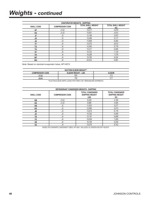
Weights - continued EVAPORATOR WEIGHTS - SHIPPING SHELL CODE COMPRESSOR CODE TOTAL SHELL WEIGHT TOTAL SHELL WEIGHT LBS KG HF J1/J2 10,317 4,679 HH J1/J2 10,831 4,912 JF J3 13,168 5,972 JG J3 13,489 6,117 JH J3 13,808 6,262 TF J4 14,575 6,610 TG J4 14,945 6,778 TH J4 15,317 6,946 VF J4 15,722 7,130 VH J4 16,268 7,378 WF J4 18,796 8,524 WH J4 20,023 9,081 Note: Based on standard evaporator tubes, MTI #272. SUCTION ELBOW WEIGHT** COMPRESSOR CODE ELBOW WEIGHT - LBS ELBOW J1/J2 600 272 J3/J4 700 317 **SUCTION ELBOW SHIPS LOOSE FOR FORM 3 OR 7 BREAKDOWN SHIPMENTS. SHELL CODE REFRIGERANT CONDENSER WEIGHTS - SHIPPING COMPRESSOR CODE TOTAL CONDENSER SHIPPING WEIGHT LBS TOTAL CONDENSER SHIPPING WEIGHT KG GB J1/J2 9,228 4,185 GD J1/J2 9,888 4,484 HB J2 11,635 5,277 HD J2 12,068 5,473 JB J3 13,619 6,176 JD J3 14,330 6,499 TB J4 15,187 6,888 TD J4 16,009 7,260 VB J4 18,168 8,239 VD J4 19,276 8,742 BASED ON STANDARD CONDENSER TUBES, MTI #261. INCLUDES OIL RESERVOIR DRY WEIGHT. 48 JOHNSON CONTROLS
Guide Specifications FORM 160.67-EG1 (308) GENERAL Furnish and install where indicated on the drawings____ YORK <strong>YST</strong> MaxE <strong>Centrifugal</strong> <strong>Liquid</strong> Chilling Unit(s). Each unit shall produce a capacity ____ of tonR, cooling ____ GPM of ____ from ____ °F to ____ °F when supplied with ____ GPM of condenser water at ____ °F. <strong>Steam</strong> consumption shall not exceed ____ lbs/hr with an IPLV (APLV) of ____. The evaporator shall be selected for____ hrft2°F/BTU fouling factor and a maximum liquid pressure drop of ____ ft. Water side shall be designed for ___ psig working pressure. The refrigerant condenser shall be selected for ____ hrft2°F/BTU fouling factor and the steam condenser shall have a cleanliness factor of ____. The maximum refrigerant and steam condenser pressure drip shall be ____ ft. Waterside shall be designed for ___ psig working pressure. <strong>Steam</strong> shall be supplied to the turbine at ____ psig and ____ °F. (or) Furnish and install where indicated on the drawings ___YORK <strong>YST</strong> MaxE <strong>Centrifugal</strong> <strong>Liquid</strong> Chilling Unit(s). Each unit shall produce a capacity of ____ kW, cooling ____ l/s of ____ from ____ °C to ____ °C when supplied with ____ l/s of condenser water at ____°C. <strong>Steam</strong> consumption shall not exceed ____ kg/hr with an IPLV (APLV) of ____. The evaporator shall be selected for ____ m2K/kW fouling factor and maximum liquid pressure drop of ____kPa. Waterside shall be designed for ___ barg working pressure. The refrigerant condenser shall be selected for ____ m2K/kW fouling factor and the steam condenser shall have a cleanliness factor of ____. The maximum refrigerant and steam condenser pressure drop shall be ____kPa. Waterside shall be designed for ___ barg working pressure. <strong>Steam</strong> shall be supplied to the turbine at ____ barg and ____ °C. Each unit shall be factory-packaged including evaporator, refrigerant condenser, sub-cooler, <strong>com</strong>pressor, steam turbine, lubrication system, Power Panel, Programmable Control Center and all inter-connecting unit piping and wiring. A steam condenser shall be shipped separately and will be suitable for mounting on the refrigerant condenser. When specified, the steam condenser may be placed on the floor adjacent to the chiller (Customer to confirm which arrangement before the order is placed). The chiller shall be painted prior to shipment. The initial charge of oil and refrigerant shall be supplied, shipped in containers and cylinders for field installation or factory charged in the chiller. POWER PANEL All motor contactors and circuit protectors, the <strong>com</strong>pressor oil pump variable speed drive and the control power JOHNSON CONTROLS transformer shall be contained in an enclosure installed adjacent to the OptiView control center. A main power disconnect switch shall be supplied which provides the termination points for the customer’s single point power supply wiring. PROGRAMMABLE CONTROL CENTER The Programmable Control Center shall be factorymounted, wired and tested microprocessor based control system for R134a centrifugal chillers. The panel shall be configured with a 10.4". diagonal color <strong>Liquid</strong> Crystal Display (LCD) surrounded by “soft” keys, which are redefined with one keystroke based on the screen displayed at that time. The LCD display shall provide a graphical and animated display of the chiller, chiller sub-systems and system parameters, allowing the presentation of several operating parameters at once. A Status Bar shall be displayed at all times on all screens containing the System - Status Line and Details Line, the Control Source, Access Level, Time and Date. During turbine slow roll, startup, operation and coastdown, the system status shall indicate vital information available at any time. Data shall be displayed in either English or SI units. Security access shall be provided to prevent unauthorized changes of setpoints. There must be different levels of access including a servicing level which shall provide diagnostics and troubleshooting information for the chiller and panel. Password protection shall be provided for all access levels. The control center power supply is provided from a fused 2KVA transformer located in the power panel. The control center is also fused to provide individual overcurrent protected power for the remote mounted water pump motor starters (supplied by others) and the controls installed on the chiller. Numbered terminal strips for wiring such as Remote Start / Stop, Chilled Water Pump and Local or Remote Cycling devices shall be provided. The Panel must also provide field interlocks that indicate the chiller status. These contacts shall include a Remote Mode Ready-to-Start, a Controlled Shutdown, a Safety Shutdown and a chiller Run contact. System pressures shall be monitored with transmitters (4-20 mA) and transducers (0-5 VDC). System temperatures shall be monitored using thermistors and RTD’s. Setpoints can be changeable from a remote location via 0-10VDC and 4-20mA, contact closures or through serial <strong>com</strong>munications. Serial data interface to the Building 49