
You also want an ePaper? Increase the reach of your titles
YUMPU automatically turns print PDFs into web optimized ePapers that Google loves.
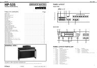
JX-305 Sep. 1998<br />
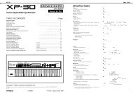
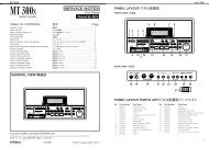
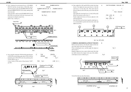
2) Next, aligning the positioning bosses of RUBBER<br />
SWITCH with the circular holes of SPACER, and as<br />
done for the spacer, place four RUBBER SWITCH 12PL,<br />
and one RUBBER SWITCH 13P in order, starting on the<br />
lower tone side.<br />
In this procedure, make sure that RUBBER SWITCH and<br />
SPACER are positioned with their cutout parts and<br />
ascape grooves aligned, respectively.<br />
(Refer to fig. 3 and fig. 4.)<br />
Cutout Part<br />
<br />
<br />
<br />
<br />
<br />
<br />
<br />
<br />
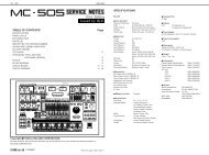
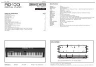
4) Then, tighten the LOW and HI PCBs with the Tap Tight<br />
Screws. First tighten the near-center Screws 1, then the<br />
end Screws 2 on the other side. (This order must be<br />
followd. Ohterwise the PCBs may not be flush with the<br />
Spacers.)<br />
Then tighten the remaining Screws 3 of the LOW and HI<br />
PCBs. (For the above, refer to Fig. 7.)<br />
Finally, tighten the Screws in the area adjacent to the<br />
LOW and HI PCBs.<br />
Since the PCBs may have been warped by soldering, etc.,<br />
it is recommended to gently hole down the center and<br />
tighten the Screws.<br />
<br />
<br />
<br />
<br />
<br />
<br />
<br />
<br />
<br />
<br />
<br />
<br />
2<br />
3<br />
1<br />
PCB Adjacent Area<br />
<br />
fig.3<br />
Air-Escape Groove<br />
<br />
RUBBER SWITCH<br />
fig.7 (ex. 32P LOW)<br />
fig.4<br />
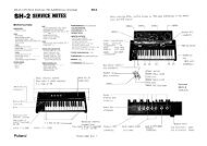
3) Next, using the cutout part of PCB and the projecting part<br />
of SPACER as positioning guide, place PCB so that the<br />
positioning pin of SPACER fits into the positioning hole<br />
of PCB. (Refer to fig. 5)<br />
As fig. 6 shows, PCBs consist of three boards, "LOW"<br />
and "HI".<br />
Posisioning Boss(6 points)<br />
<br />
PCB SPACER<br />
Chassis<br />
<br />
<br />
<br />
<br />
<br />
<br />
Positioning Pin of SPACER<br />
<br />
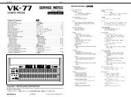
2. REMOVAL AND REINSTALLATION OF THE KEYS<br />
Before removing the keys, first take the stopper off the rear<br />
side of the chassis, then take away the spring.<br />
When reinstalling the keys, carefully apply the stopper as<br />
shown in fig. 8.<br />
Bring the stopper into closs contact with the ends of the white<br />
key shafts and press the stopper in the area of the doublecoated<br />
tape to secure it. (Refer fig. 8.)<br />
<br />
<br />
<br />
<br />
<br />
<br />
<br />
<br />
Double-Coated<br />
Adhesive Tape<br />
<br />
Stopper<br />
<br />
PCB Cutout Part<br />
fig.5<br />
fig.8<br />
Normal<br />
Key Axis<br />
<br />
Sharp Key Axis<br />
<br />
Projecting Part of SPACER<br />
<br />
Viewed from the rear side of the chassis.<br />
<br />
32P LOW<br />
29P HI<br />
32P LOW<br />
29P HI<br />
Bass Side<br />
<br />
fig.6<br />
Treble Side<br />
<br />
STOPPER 12P x4<br />
fig.9<br />
STOPPER 13P<br />
17