Vektor-CD Performance Catalog - Greenheck
Vektor-CD Performance Catalog - Greenheck
Vektor-CD Performance Catalog - Greenheck

Create successful ePaper yourself
Turn your PDF publications into a flip-book with our unique Google optimized e-Paper software.
AMCA 260 Air Test Procedure<br />
The following illustrations describe the procedure for determining the total laboratory exhaust fan discharge flow.<br />
The total discharge flow is the sum of fan flow and entrained dilution airflow. The key requirement to AMCA 260<br />
is the AMCA Accredited variable resistance box. This box allows the fan to be discharged into the air chamber<br />
(Ps = 0 in. wg to simulate discharging the fan to atmosphere) at all points along its fan curve.<br />
Without the variable resistance box, the entrained dilution airflow can only be measured at the free air point of its<br />
fan curve. The entrained dilution airflow obtained can be used to calculate an effective plume height. Therefore,<br />
AMCA 260 certification is necessary to ensure the laboratory exhaust fan specified is providing the plume rise<br />
and entrainment submitted.<br />
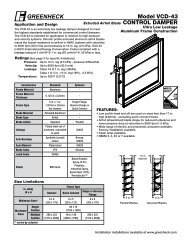
ANSI/AMCA 210 Figure 15 Test<br />
Total Flow<br />
Total Airflow<br />
AMCA Accredited Air Test Chamber<br />
Airflow<br />
Flow Direction<br />
Entrained<br />
Air<br />
Variable<br />
Supply<br />
System<br />
Total Airflow Measurement<br />
Determines inlet airflow (cfm).<br />
Airflow<br />
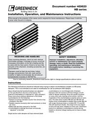
AMCA 260 Figure 1 Test<br />
Variable Resistance Box<br />
Flow Direction<br />
AMCA Accredited Air Test Chamber<br />
Total Flow<br />
Flow Direction<br />
Total Flow Airflow<br />
6<br />
Entrained<br />
Air<br />
Ps = 0 in. wg*<br />
Total Airflow Measurement<br />
*To simulate atmospheric conditions<br />
Determines outlet airflow (cfm) at the same inlet<br />
conditions measured in the Figure 15 test.<br />
Variable<br />
Exhaust<br />
System