Hydraulic Drives for Bridges Considering the New DIN Standard ...
Hydraulic Drives for Bridges Considering the New DIN Standard ...
Hydraulic Drives for Bridges Considering the New DIN Standard ...
Create successful ePaper yourself
Turn your PDF publications into a flip-book with our unique Google optimized e-Paper software.
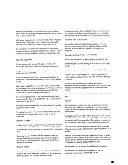
<strong>Hydraulic</strong> cylinders which are submerged temporarily or over a longer<br />
period of time, should be monitored <strong>for</strong> leakage by suitable means. These<br />
must be specified by <strong>the</strong> client.<br />
Both cylinder chambers must be permanenrly filled with oil. If <strong>the</strong> gate is<br />
lowered without <strong>the</strong> pumps running, it must be ensured by suitable<br />
measures that <strong>the</strong> pressureless cylinder chamber is filled with oil.<br />
For proper bleeding of <strong>the</strong> hydraulic cylinder, pressure measurement<br />
connections must be provided at suitable locations. If required, a suitable<br />
procedure must be specified <strong>for</strong> <strong>the</strong> assembly and filling of <strong>the</strong> cylinder.<br />
<strong>Hydraulic</strong> components<br />
Pressure is generated by pumps which operate according to <strong>the</strong><br />
displacement principle with fixed or steplessly variable displacement.<br />
For systems with heavily fluctuating flows, pumps with variable<br />
displacement are recommended.<br />
It must be possible to replace motors and pumps without having to<br />
remove o<strong>the</strong>r components. Motors have to be mounted on anti-vibration<br />
mounts.<br />
All <strong>the</strong> devices required <strong>for</strong> <strong>the</strong> control of <strong>the</strong> hydraulic system such as<br />
directional valves, flow control valves, pressure relief valves, etc. have to be<br />
clearly arranged on common control plates wherever possible. The<br />
actuator ports are d~rectly connected to <strong>the</strong> manifolds.<br />
For electrically operated valves, DC wet-pin solenoids should be used<br />
whereever possible. These valves shall be fitted with an easily accessible<br />
manual override with detent.<br />
Pilot operated directional valves have to be indicated by LEDs, except <strong>for</strong><br />
proportional and servo-valves.<br />
The electrical connnection <strong>for</strong> any electrical components such as valves.<br />
pressure switches and float switches must be made via plug-in<br />
connections.<br />
<strong>Hydraulic</strong> oil filters<br />
<strong>Hydraulic</strong> stations have to be fitted with ar least one return line filler with<br />
a maximum filter rating of 20 m with non recycable insens. Paper filters<br />
are not permitted.The filter system must be matched with <strong>the</strong> components<br />
used.<br />
The nominal flow rate of <strong>the</strong> filter should at least be four times <strong>the</strong><br />
maximum flow. All filters have to be provided with a visual clogging<br />
indicator, with an electrical connection and a by-pass valve having an<br />
opening pressure of 3 bar.<br />
<strong>Hydraulic</strong> stations<br />
The design can be compact, e.g. oil reservoir with mounted-on motor1<br />
pump units and control, or individual assemblies, e.g. oil reservoir, pump<br />
station, valve station and, if required, accumulator station.<br />
Oil reservoirs have to be dimensioned sufficiently large to accommodate<br />
four times <strong>the</strong> volume of <strong>the</strong> maximum flow supplied by <strong>the</strong> pump(s) in<br />
one minute, plus <strong>the</strong> pendulum volume of all connected cylinders, plus <strong>the</strong><br />
contents of <strong>the</strong> piston rod chamber of <strong>the</strong> largest connected cylinder plus<br />
<strong>the</strong> contents of <strong>the</strong> associated pipes.<br />
Reservoirs have to be designed with an oilique bottom, dram valve,<br />
cleaning openings, permanent oil level inditator and float switch. The<br />
latter must be removable wirhout requiring <strong>the</strong> removal of o<strong>the</strong>r<br />
components.<br />
Fillet welds must be double-sided whenever possible<br />
Venting of <strong>the</strong> reservoir must be realised via a humidity adsorber with<br />
transparent container. Air escaping when <strong>the</strong> oil level Increases mut not be<br />
directed through <strong>the</strong> adsorber. Openings in <strong>the</strong> reservoir must be plugged<br />
air-tight.<br />
In general, fittings and valves shall not be arranged within <strong>the</strong> oil reservoir,<br />
If <strong>the</strong> drlve rooms cannot be deigned to 3.3, <strong>the</strong> o ~l reservoir must be<br />
erected in a steel sheet tray, wh~ch corresponds to <strong>the</strong> nominal capacity of<br />
<strong>the</strong> reservoir.<br />
<strong>Hydraulic</strong> variable displacement pumps should be installed in a<br />
rnaintenance-friendly manner next to <strong>the</strong> reservoir. The suction lines have<br />
to be equipped with manually operated shut-off valve with limit switch<br />
monitor.<br />
In general, <strong>the</strong> required total flow is subdivided to at least 2 motor/pump<br />
units.<br />
Pipework<br />
When determining <strong>the</strong> routing of <strong>the</strong> pipes, good accessibility must be<br />
taken into account. The distance of pipes must be so that fittings and<br />
flanges can be mounted without difficulties. The pipes should not be laid<br />
onto each o<strong>the</strong>r.<br />
Moved parts, movable connections and expansion joints have to be fitted<br />
with flexible hydraulic hoses. Only hoses to <strong>DIN</strong> 20066 in conjunction with<br />
corrosion-protected fittings are permitted. The installation instructions to<br />
<strong>DIN</strong> 20066-4 have to be observed. The use of rotary joints is permitted.<br />
If <strong>the</strong> arrangement of pipe or hose lines in flowing water or in its direct<br />
vicinity cannot be avoided, protective measures against flotsam have to be<br />
provided.<br />
Pipes have to be fitted with manually operated shut-off valves <strong>for</strong> partial<br />
shutdowns, at least at <strong>the</strong> porn of <strong>the</strong> hydraulic statlon and at <strong>the</strong> pons of<br />
hydraulic cylinders and hydraulic motors. Equipment with additional shutoff<br />
valves, e.g. on hoses, has to be specified by rhe client.<br />
Depressurization must be possible - if required, also <strong>for</strong> sub-sections.<br />
Proper bleeding of <strong>the</strong> pipe system must be ensured. Pressure<br />
measurement connections are reccommended <strong>for</strong> this.


