Shatt-Al-Basrah Bridge A Swing Bridge with a Hydraulic Drive
Shatt-Al-Basrah Bridge A Swing Bridge with a Hydraulic Drive
Shatt-Al-Basrah Bridge A Swing Bridge with a Hydraulic Drive
Create successful ePaper yourself
Turn your PDF publications into a flip-book with our unique Google optimized e-Paper software.
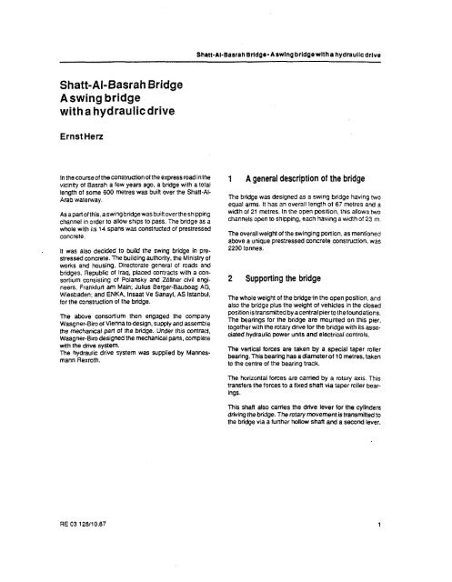
Shltt-<strong>Al</strong>-<strong>Basrah</strong> Brldge. Aswlng brldgewltha hydraullcdrive<strong>Shatt</strong>-<strong>Al</strong>-<strong>Basrah</strong> <strong>Bridge</strong>Aswing bridge<strong>with</strong>a hydraulicdriveErnst HerzInthecourseoftheWnstruc(ion0fthe expressroadinthevicinity of <strong>Basrah</strong> a few years ago, a bridge <strong>with</strong> a totallength of some 600 metres was buiii over the <strong>Shatt</strong>-<strong>Al</strong>-Arab waterway.Asapartofthis, aswingbridgewasbuiltovertheshippingchannel in order to allow ships to pass. The bridge as awhole <strong>with</strong> its 14 spans was constructed of prestressedconcrete.It was also decided to build the swing bridge in prestressedconcrete. The building authority, the Ministry ofworks and housing, Directorate general of mads andbridges. Republic of Iraq, placed contracts <strong>with</strong> a consortiumconsisting Of Polansky and Zdllner civil engineers,Frankfurt am Main; Julius Berger-Bauboag AG,Wiesbaden; and ENKA, lnsaat Ve Sanayi, AS Istanbul,for the mnstruction of the bridge.The above consortium then engaged the companyWaagner-Biroof Viennato design, supply and assemhiethe mechanical pati of the bridge. Under this contract,Waagner-Bim designed the mechanical parts. complete<strong>with</strong> the drive system.me hydraulic drive system was supplied by MannesmannRexroth.1 A general description of the bridgeThe bridae was desianed as a swinq bridae having twoequal ark It has ~noverali lenqhbl 67metres and awldln of 21 metres In the open wsition, thls allows twochannels open to shipping, each having a widlh of 23 m.The overall weight of the swinging portion, as mentionedabove a unique . prestressed . concrete construction, was2200 tonnes.2 Supporting the bridgeThe whole weighl of the bridge.inthe open position, andalso the bridge plus the weigM of vehicles in the closedwsilionistransminedbvacentraloiertothefoundations.he bearings for the bridge are .munted on this pier,together<strong>with</strong> the mtary drive for the bridge <strong>with</strong> its associatedhydraulic power unns and electrical controls.The venlcal forces are taken by a spec~al taper rollerbeannq Th~s beanng has a d~ameterof 10 metres, takento the centre of the bearing track.The horizontal forces are carried by a rotary axis. Thistransfers the forces to a fixed shan via taper roller bearings.Thii Shan also carries me drive lever for the cviinders , ~~~driving the bridge. The rotary movemem is transmined tothe bridge via a further hollow shan and a second lever.
<strong>Shatt</strong>-<strong>Al</strong>-<strong>Basrah</strong> Brldge.Aswlng brldgewnha hydraullcdrlveThe design of the bearings for the bridge is shown infigure 1.Fig. 1:Shaft-<strong>Al</strong>-<strong>Basrah</strong> bridge, bridge bearing
Shan-<strong>Al</strong>-<strong>Basrah</strong>Brldpe.ASWln(l brldgewltha hydraullcdrlveFigureZshows a detailof the taper rollerbearings. Fromthisdiagram, it canbeseen thatthe480 mmdiameterrollenare carried in an annular cage. Each roller is Indwiduallvadiustable, so that all 42 rollers cany an equal;hare ofthe welgh1 <strong>Al</strong>l rollers are equpped <strong>with</strong> an automatc lubr~cal~on system in order lo m~nlmtse the SeNlcingrequirements of this large bearing.I 1IFig. 2:Shan-M<strong>Basrah</strong> bridge, bridge W n g and drive system
Shatl-<strong>Al</strong>-<strong>Basrah</strong> Brldge. ASwlng brldgewltha hydraullcdrlve3 The rotary driveThe rotary drive to the bridge isvia four plunger cylindersworking in opposed pairs so that two are active (extending),and two passive (retracting), in each direction ofrotation. The cylinders and the dwe system are bothdesignedsothat shouldafailureocwr,the bridge may beoperated by one cylinder.Due to the opposed hydraulic cylinders, the bridge is alwayshydraulically restrained toensurethat innocircumstancescan & run away.Figure 3 shows the drive cylinders. <strong>Al</strong>so in figure 3, thearrangement of the 42 tapered rollers can once more beseen.
<strong>Shatt</strong>-<strong>Al</strong>-<strong>Basrah</strong>Brldge- Aswlng brldge<strong>with</strong>a hydraulicdrive4 The locking systemIn the closed (traffic) position, the bridge is locked at 4poims, <strong>with</strong> rwo separate systems at the ends of thebridge. In view of the unusual wetght of the bridge, aspecial design of liiingilocking system had to be producedby Waagner Biro.AS mentioned earlier, the bridge is of hollow section prestressedconcrete. The bcking device for the bridge isfined <strong>with</strong>in these hoilow sections. The lining section ofthe lo&, and also the mating pans for the lockingdevices are mourned in the fixed sections of the bridge.This separate arrangement of the locking and liftingmechanisms was necessary due to the bridge bendingsome 150 mm during the opening phase. Such a largebending mvemem cannot be accepted by a speciallyformed locking device, and must be taken up by theseparate lining mechanism.The locking mechanism munted in the moving bridgeconsists of lwo locks 5700 mm apart at each end of thebndge, mounted in a steel framewoh. The bolts are ofrectangular section 400 x 550 mrn. Both verliil andhorkontal guides have roller bearings, thus perminingthe kking forces to be relatively low. The drive to thekks is via a direct coupled hydraulic qlinder. The designcan be seen in figure 4..LFQ. 4: Siutl-#BaMh W e , bdr4 systemI
<strong>Shatt</strong>-<strong>Al</strong>-<strong>Basrah</strong> <strong>Bridge</strong>. Aswtng brldgewltha hydraullcdrlveThe lifting mechanism fitted into the fixed sections of thebridge are also equipped <strong>with</strong> extending locking pins.When the bridge has been swung into the trafficposition,the locking pins extend from the moving ponion in orderto engage in the fixed sedions. In orderto centralise thebridge, oneofthefourlockingpinsisdesignedasalocatingpin. When the bridge has been centralised, the liltingcvlinders lift the ends of the bridgevia the extended lockpmsunt~l the surface of the %vlng and flied seatonsare atthesame he~ghl Wnenth~stour horucntal .ocklng plrs are then entered under thepreviously extended 1ock:ng pins from the moving section,in order to hold the bridge at the correcf height.Finally, the liming mechanism is lowered, lowering thebridge onto the fixed supporls. me lifting mechanism isthus unloaded.me hydraulic drive to the liming device can be seen infigure 5.Whenopeningthe bridge, the above process isreversed.The lifting cylinders are extended, the hoeontal locks<strong>with</strong>drawn, the bridge lowered, and the extending locksretracted, allowing the bridge to bend to its free position.Thebriieisthenoncemoreonfy supporledonthetaperroller bearing on the centre pier.has beenachteved the 5 The hydraulic driveThe bridge has now been wo*ing for a number of yeanto the entire satisfaction of the specaying authority. Shehydraulics operate perfectly in spite of the adverse environmentalccndiiions (frequent sand storms).At this point, we would paniarlarly like to thank WaagnerB ~ ~ for O their cooperation and kindness in passing informationto us, thus allowino this resenta at ion to be pro-IFig. 5: Shan-<strong>Al</strong>-<strong>Basrah</strong> bridge. locking sysemI
<strong>Shatt</strong>-<strong>Al</strong>-<strong>Basrah</strong> Brldge. Aswlng bridge<strong>with</strong>a hydraullcdrlveNotes
<strong>Shatt</strong>-<strong>Al</strong>-<strong>Basrah</strong>Brldge- Aswlng brldge<strong>with</strong>ahydraullcdrlveNotes


