Newton's Second Law VTL - Ryerson Department of Physics
Newton's Second Law VTL - Ryerson Department of Physics
Newton's Second Law VTL - Ryerson Department of Physics

You also want an ePaper? Increase the reach of your titles
YUMPU automatically turns print PDFs into web optimized ePapers that Google loves.
Newton’s <strong>Second</strong> <strong>Law</strong><br />
Objective<br />
The purpose <strong>of</strong> this experiment is to show the relationship between force and<br />
acceleration in a friction-free environment and to illustrate the concept <strong>of</strong> mass.<br />
Apparatus<br />
Air-cushioned track and glider<br />
Weights and hanger<br />
String<br />
Pulley and clamps<br />
Vernier Lab Pro<br />
2 Vernier photogates<br />
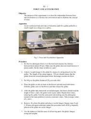
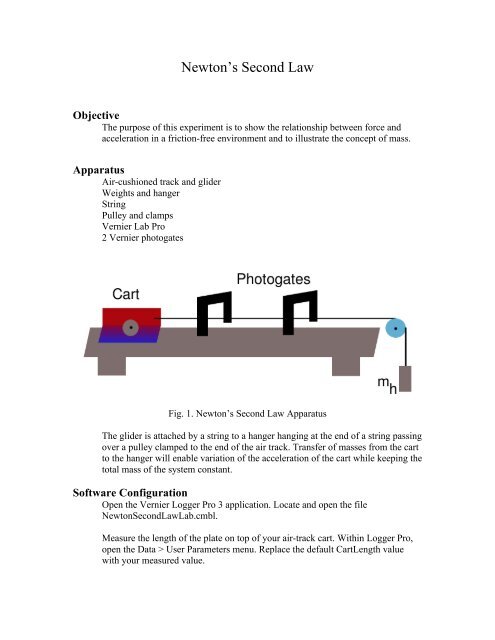
Fig. 1. Newton’s <strong>Second</strong> <strong>Law</strong> Apparatus<br />
The glider is attached by a string to a hanger hanging at the end <strong>of</strong> a string passing<br />
over a pulley clamped to the end <strong>of</strong> the air track. Transfer <strong>of</strong> masses from the cart<br />
to the hanger will enable variation <strong>of</strong> the acceleration <strong>of</strong> the cart while keeping the<br />
total mass <strong>of</strong> the system constant.<br />
S<strong>of</strong>tware Configuration<br />
Open the Vernier Logger Pro 3 application. Locate and open the file<br />
Newton<strong>Second</strong><strong>Law</strong>Lab.cmbl.<br />
Measure the length <strong>of</strong> the plate on top <strong>of</strong> your air-track cart. Within Logger Pro,<br />
open the Data > User Parameters menu. Replace the default CartLength value<br />
with your measured value.
Procedure<br />
1. Set the two photogate timers over the track. Measure and record the distance<br />
L between the photogates (make L about 60 cm). Make sure the cart does not<br />
touch them as it passes underneath. Note, the distance L between the gates must<br />
remain the same for all trials.<br />
2. Attach a weight hanger to the glider by means <strong>of</strong> a string placed over the<br />
pulley. The length <strong>of</strong> the string (approx. 130 cm) should ensure that the glider<br />
clears the second photogate before the hanger touches the floor.<br />
3. Put 40 g on the glider (balanced 20 g on each side).<br />
4. Place the glider on the track at the starting position. Mark the starting position<br />
with masking tape and a pencil mark, such that additional trials start from the<br />
same place. Hold the glider and press the “Start Collection” button on the Logger<br />
Pro screen. Release the glider.<br />
5. After the glider has cleared the second photogate, the timers should read the<br />
length <strong>of</strong> time t1 and t2 the glider took to pass under. Click Experiment > Store<br />
Latest Run to store the data.<br />
Repeat three times, releasing the cart from the same point and making sure the<br />
photogates remain in the same position to ensure consistent values. Take average<br />
values <strong>of</strong> v1 and v2.<br />
[Note, it is recommended to save your data for each set <strong>of</strong> three trials <strong>of</strong> a<br />
particular mass, e.g. Trials-Mass5g, Trials-Mass15g, etc. Save each file to the<br />
Desktop <strong>of</strong> the computer. Once all trials have been completed, copy the files to a<br />
USB key or e-mail to your account. All data is automatically deleted from the<br />
computers at log<strong>of</strong>f.]<br />
6. Remove 10 g from the glider and place it on the hanger. Repeat steps 4 and 5.<br />
If times are again consistent repeat this procedure until all 40 g originally placed<br />
on the cart are on the hanger.<br />
7. Use the balance to find the mass <strong>of</strong> all moving parts: the glider, hanger, string<br />
and weights.<br />
Calculations<br />
We will use<br />
v 2 2 = v 1 2 + 2aL
to find the acceleration for each weight where L is the distance between<br />
the photogates. The velocities v 1 and v 2 are found by dividing the length <strong>of</strong><br />
the gliding cart l, by the time t 1 and t 2 respectively, taken to pass under<br />
each photogate:<br />
l<br />
v<br />
1<br />
= and<br />
t<br />
1<br />
v =<br />
2<br />
l<br />
t<br />
2<br />
The force causing acceleration is given by F h = mg where m (expressed in<br />
kg) is the total mass <strong>of</strong> the hanger and weights placed on it and g is the<br />
acceleration <strong>of</strong> gravity (g = 9.8 m/s 2 ).<br />
Table 1: Observations and Results for Newton’s <strong>Second</strong> <strong>Law</strong><br />
m h F h<br />
l L<br />
t 1 t 2 v 1 v 2<br />
a<br />
(kg)<br />
(N)<br />
(m)<br />
(m)<br />
(s)<br />
(s)<br />
(m/s)<br />
(m/s)<br />
(m/s 2 )<br />
Analysis<br />
Plot a graph <strong>of</strong> acceleration (y-axis) versus force (x-axis). Find the slope <strong>of</strong><br />
the best straight line through the points. The value <strong>of</strong> the slope is the<br />
constant <strong>of</strong> proportionality between acceleration and force. Compare this<br />
value to the reciprocal <strong>of</strong> the mass <strong>of</strong> the glider, hanger and the 40 g<br />
masses as obtained on the balance.