CENTRIPETAL FORCE - Ryerson Department of Physics
CENTRIPETAL FORCE - Ryerson Department of Physics
CENTRIPETAL FORCE - Ryerson Department of Physics

You also want an ePaper? Increase the reach of your titles
YUMPU automatically turns print PDFs into web optimized ePapers that Google loves.
D6-1<br />
<strong>CENTRIPETAL</strong> <strong>FORCE</strong><br />
OBJECTIVE<br />
The objective <strong>of</strong> this lab is to measure the centripetal force acting on a mass undergoing angular<br />
motion and its centripetal acceleration.<br />
INTRODUCTION<br />
An object moving along a circular path at constant speed v experiences uniform circular motion.<br />
Even though the object moves with constant speed it has acceleration due to the change in the<br />
direction <strong>of</strong> the vector velocity. Since its direction is towards the centre <strong>of</strong> the circular path in a<br />
radial direction this acceleration is known by the names <strong>of</strong> centripetal acceleration or radial<br />
acceleration.<br />
The Magnitude <strong>of</strong> this acceleration is<br />
where r is the radius <strong>of</strong> the circular path. One can also express the centripetal acceleration in terms <strong>of</strong><br />
the angular speed ω:<br />
since , then<br />
To the centripetal acceleration corresponds a force, the centripetal force, whose magnitude is:<br />
and whose direction is evidently towards the centre <strong>of</strong> the path.<br />
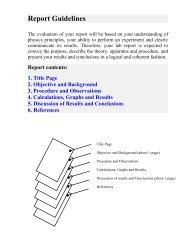
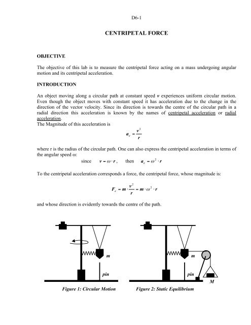
m<br />
m<br />
pin<br />
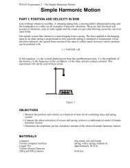
Figure 1: Circular Motion<br />
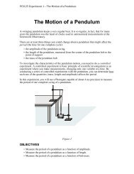
pin<br />
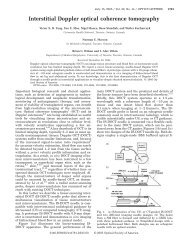
Figure 2: Static Equilibrium<br />
M
D6-2<br />
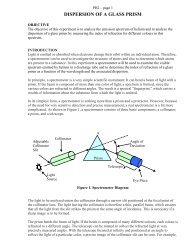
The apparatus for this experiment consists <strong>of</strong> a vertical shaft (which is fit into a bearing) with a<br />
horizontal cross arm attached to the top <strong>of</strong> it (see Figure 1). On one end <strong>of</strong> the cross arm there is a<br />
counterweight (which should remain fixed in place for the duration <strong>of</strong> the experiment) and on the<br />
other end there is a mass m, which is suspended from a string and is attached to the vertical shaft via<br />
a spring.<br />
When the shaft is rotated, the mass m has a tendency to swing outward. You should observe that as<br />
you spin the shaft (by applying a torque with your fingers) the hanging mass m moves outward and<br />
stretches the spring. The faster you spin the shaft, the further and further away from the shaft the<br />
mass will move. Clearly, the spring joining the mass to the shaft resists to the outward motion <strong>of</strong> the<br />
mass.<br />
The number <strong>of</strong> revolutions per second performed by the mass can be observed visually. The radius<br />
<strong>of</strong> rotation can be measured with the help <strong>of</strong> a pin on the base <strong>of</strong> the apparatus (see Figure 1) and<br />
whose position can be changed. To determine its value let the mass m hang free (i.e. detach the<br />
spring from it) and adjust the position <strong>of</strong> the pin so that it lies directly below the freely hanging<br />
mass. The value <strong>of</strong> the radius <strong>of</strong> rotation is given then by the distance <strong>of</strong> the pin to the centre <strong>of</strong> the<br />
vertical shaft. When you reattach the spring to the mass and set it in motion, the pin will then act as a<br />
visual indicator as to when the mass has returned to this vertical position. The radius <strong>of</strong> rotation stays<br />
constant when the angular speed is constant.<br />
To verify the equation that governs the uniform circular motion (<br />
) you will measure<br />
several values for the centripetal force and corresponding centripetal acceleration <strong>of</strong> the<br />
hanging mass. From this data you will determine an experimental value <strong>of</strong> the mass m.<br />
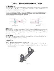
The centripetal force will be found by measuring the force required to stretch the spring so that the<br />
mass m hangs vertically above the pin (see Figure 2). That is, when not in motion, suitable masses<br />
M, attached to the mass m by a string over a pulley, should cause the same extension <strong>of</strong> the spring as<br />
when the system is in motion.<br />
The centripetal acceleration will be determined from the measured values <strong>of</strong> the radius <strong>of</strong> rotation<br />
and corresponding angular speed.<br />
PROCEDURE<br />
1. Detach the mass m from the spring and string. Measure its mass and record this value. With a<br />
pair <strong>of</strong> vernier calipers measure the diameter <strong>of</strong> the vertical shaft and record this value.<br />
2. Place the mass back on the string. Loosen the setscrew that holds the cross arm in place and<br />
adjust the position <strong>of</strong> the cross arm so that the point at the bottom <strong>of</strong> the mass M is about 14 cm<br />
from the shaft, and then fix the cross arm in place using the setscrew. This distance will represent<br />
the smallest radius <strong>of</strong> rotation for your experiment. Move the pin so that the top <strong>of</strong> the pin is<br />
located just below the point at the bottom <strong>of</strong> hanging mass (see Figure 1). Reattach the spring to<br />
the hanging mass.
D6-3<br />
3. In order to measure the radius <strong>of</strong> the path that the mass will be following, measure the distance<br />
between the pin and the shaft and record this value. This distance plus the radius <strong>of</strong> the shaft<br />
(measured in step 1) will give you the radius r, <strong>of</strong> the path when the mass is undergoing uniform<br />
circular motion directly over the pin.<br />
4. Practice spinning the shaft. Once you get used to it, you should be able to spin the shaft at the<br />
right speed so that the mass travels in a circular path directly above the pin. A sheet <strong>of</strong> white<br />
paper held behind the pin will probably be useful in seeing when the mass passes exactly over<br />
the pin. Once you are comfortable that you can maintain a stable angular speed, time how long it<br />
takes for the mass to complete 25 full rotations and get three separate trials. For each trial<br />
calculate the angular speed <strong>of</strong> the cross arm (in radians per second) and then take the average <strong>of</strong><br />
the three trials. From the average value <strong>of</strong> ω calculate the centripetal acceleration <strong>of</strong> the spinning<br />
mass using , where r is the radius (in metres) <strong>of</strong> the circular path found from step 3.<br />
5. To measure the centripetal force (F c ) on the mass M take the mass holder and attach a piece <strong>of</strong><br />
string from the mass holder to hanging mass. Add weights to the mass holder until the mass m is<br />
in static equilibrium directly over the pin (see Figure 2). The force <strong>of</strong> gravity acting on the mass<br />
(M) <strong>of</strong> the holder plus the weights, should be equivalent to the centripetal force that was needed<br />
to keep the hanging mass moving in a circle above the pin. Record this value as your centripetal<br />
force.<br />
6. Repeat steps 2-5 above using 4 other larger radii. Altogether, you should have five different<br />
values for the radius and corresponding values for centripetal accelerations and centripetal<br />
forces.<br />
7. If you have not already done so, plot a graph <strong>of</strong> F c vs. a c (you can use Maple or graph paper) and<br />
find the slope <strong>of</strong> the line that best represents your data values. Compare the value <strong>of</strong> the slope <strong>of</strong><br />
this line to the value <strong>of</strong> the hanging mass measured in step 1.
D6-4<br />
PRELAB QUESTIONS<br />
1. [1.5] What is the difference between the tangential acceleration and centripetal acceleration?<br />
2. [1.5] How do you define angular speed?<br />
3. [1] Relate the period <strong>of</strong> revolution with angular velocity.<br />
4. [1] What is the difference between centrifugal force and centripetal force.<br />
REPORT WRITING INSTRUCTIONS<br />
Read the procedure on previous two pages and prepare a table to help you record all<br />
quantities needed for this experiment.<br />
I. Procedure:<br />
Perform the experiment as instructed in the previous pages <strong>of</strong> the lab manual and fill in your data<br />
table.<br />
II. Conclusions:<br />
1. What physical quantity does the slope <strong>of</strong> the line graphed represent?<br />
2. How does the measured value for the mass m compare with the one obtained from the graph?<br />
3. How could you improve the experimental procedure so that your results would be more<br />
accurate?