Design-Build Support of Excavation for Block 76 - Nicholson ...
Design-Build Support of Excavation for Block 76 - Nicholson ...
Design-Build Support of Excavation for Block 76 - Nicholson ...

Create successful ePaper yourself
Turn your PDF publications into a flip-book with our unique Google optimized e-Paper software.
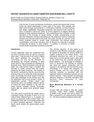
DESIGN-BUILD SUPPORT OF EXCAVATION FOR BLOCK <strong>76</strong><br />
Rick Deschamps and Tom Hurley, <strong>Nicholson</strong> Construction, Pittsburgh, PA USA<br />
The <strong>Block</strong> <strong>76</strong> project includes the demolition and redevelopment <strong>of</strong> an entire city<br />
block <strong>for</strong> mixed use retail, <strong>of</strong>fice and residential properties directly adjacent to Historic<br />
Temple Square in Salt Lake City, Utah. <strong>Excavation</strong> was carried out 65 ft below street<br />
grade and by as much as 50 ft directly below adjacent buildings supported by shallow<br />
foundations. Movements <strong>of</strong> the earth retention system and adjacent buildings were<br />
monitored in real time using automated equipment which complemented traditional<br />
geotechnical instrumentation. In the areas immediately adjacent to the existing<br />
buildings 9 stories or greater, anchored diaphragm walls were employed. Areas <strong>of</strong><br />
the site not supported by diaphragm walls employed a soil nail wall system. Jet<br />
grouting was used <strong>for</strong> water cut<strong>of</strong>f in lieu <strong>of</strong> dewatering along the north and east sides<br />
<strong>of</strong> project.<br />
In total, the earth retention scope included 45,000 sq. ft <strong>of</strong> diaphragm wall, 104,000<br />
sq. ft <strong>of</strong> soil nail wall, and micropile underpinning <strong>of</strong> 3 buildings. This paper provides<br />
an overall description <strong>of</strong> the <strong>Block</strong> <strong>76</strong> project. A detailed account is provided <strong>of</strong> the<br />
technical and commercial lessons learned. The project provided a unique example <strong>of</strong><br />
how an owner can receive best overall value by acceptance <strong>of</strong> some technical risk up<br />
front. Benefit was gained by allowing the contractor to reduce contingencies within<br />
the bid from unknowns on a fast-track project.<br />
BACKGROUND<br />
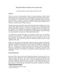
City Creek Center is a US$1 billion project in<br />
downtown Salt Lake City, Utah. The project is<br />
spread over 3 city blocks encompassing 20<br />
acres and involves the demolition and<br />
redevelopment <strong>for</strong> mixed use retail, <strong>of</strong>fice and<br />
residential properties directly adjacent to<br />
Historic Temple Square, (Figure 1).<br />
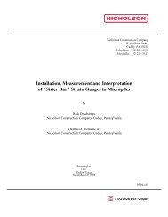
Prior to construction, <strong>Block</strong> <strong>76</strong> was occupied by<br />
an existing shopping mall, subsurface parking<br />
structure and <strong>of</strong>fice buildings. Demolition <strong>of</strong><br />
these structures, including the implosion <strong>of</strong> the<br />
Key Bank <strong>of</strong>fice tower, made way <strong>for</strong> the new<br />
construction. However an adjacent light rail<br />
system and four existing buildings between 9<br />
and 23 stories remained at the corners <strong>of</strong> the<br />
project (Figure 2).<br />
<strong>Support</strong> <strong>of</strong> excavation (SOE) work generally<br />
requires significant overlap <strong>of</strong> activities with the<br />
excavation contractor and there<strong>for</strong>e definition<br />
<strong>of</strong> work scope and schedule. A significant level<br />
<strong>of</strong> complexity was superimposed <strong>for</strong> <strong>Block</strong> <strong>76</strong><br />
because <strong>of</strong> the extensive demolition required.<br />
The fact that new, deeper basement walls<br />
would have to be constructed along the<br />
alignment <strong>of</strong> existing basement walls required<br />
coordinated activities among all three<br />
subcontractors. For this reason, <strong>Nicholson</strong> met<br />
with Grant Mackey Demolition and Reynolds<br />
Brothers <strong>Excavation</strong> be<strong>for</strong>e the bid and spent<br />
significant time to adequately define scope and<br />
to coordinate schedules. The goal was to<br />
optimize the construction processes while<br />
accounting <strong>for</strong> costs. This ef<strong>for</strong>t may seem<br />
obvious, but Construction Managers <strong>of</strong>ten<br />
New 15<br />
Story Bldgs<br />
New 30<br />
Story Bldg<br />
New Mall<br />
& Parking<br />
<strong>Block</strong> 75<br />
New 20<br />
Story Bldg<br />
Figure 1 – New Construction at <strong>Block</strong> <strong>76</strong> <strong>of</strong> the<br />
City Creek Center Project
equire individual price proposals from each<br />
subcontractor <strong>for</strong> the purpose <strong>of</strong> mixing-andmatching<br />
the subcontractors believing it will<br />
lead to the lowest overall cost to the owner.<br />
Fragmenting teams on a complex and<br />
technically challenging project is generally<br />
short sighted because the new grouping <strong>of</strong><br />
subcontractors have not coordinated their<br />
activities and adequately defined each <strong>of</strong> their<br />
scopes and schedules. The cost savings are<br />
an illusion, because the projects generally have<br />
more scope and coordination conflicts, which<br />
lead to the submission <strong>of</strong> change orders and<br />
schedule delays. In the long run the Owner<br />
rarely gets best value with this approach.<br />
Hotel<br />
Mall & Parking<br />
Figure 2 – <strong>Block</strong> <strong>76</strong> Demolition<br />
Imploded 20<br />
Story Bldg<br />
Light Rail<br />
Upfront challenges <strong>for</strong> the <strong>Block</strong> <strong>76</strong> project<br />
included:<br />
1. Rigid geometric constraints <strong>for</strong> the<br />
SOE layout. Essentially, the inside<br />
face <strong>of</strong> the retaining walls were<br />
required to be 1 ft <strong>of</strong>f the property line.<br />
2. Maximum de<strong>for</strong>mations were specified<br />
as 1 inch when excavation depths<br />
were up to 65 ft, and immediately<br />
adjacent to buildings up to 20 stories.<br />
3. The reported clay foundation strength<br />
was borderline from a base stability<br />
standpoint.<br />
4. The geotechnical pr<strong>of</strong>ile was based<br />
primarily on historic data and<br />
perimeter investigation because there<br />
was very limited access <strong>for</strong> new<br />
borings/data within the urban footprint<br />
<strong>of</strong> existing buildings.<br />
5. Groundwater was within the<br />
excavation depth on the northeast<br />
portion <strong>of</strong> the site.<br />
SOIL CONDITIONS<br />
The soil stratigraphy consists <strong>of</strong> layered alluvial<br />
and lacustrine deposits. The uppermost layer<br />
was medium to very dense sand and gravel<br />
laid down as alluvial fans from the adjacent<br />
Wastach Mountains. This gravel layer was<br />
underlain by medium to stiff clays and silts<br />
under which is a very dense layer <strong>of</strong> sand and<br />
gravel. The clay and lower gravel layer are<br />
deepest at the southwest corner <strong>of</strong> the site and<br />
rise towards the northeast corner <strong>of</strong> the site.<br />
The depth to existing groundwater is<br />
approximately 40-54 ft below grade with the<br />
highest groundwater at the northeast corner <strong>of</strong><br />
the site. Figure 3 depicts the subsurface<br />
pr<strong>of</strong>ile. (Image from Geotech report prepared<br />
by AGEC).<br />
DESIGN CONSIDERATIONS<br />
<strong>Excavation</strong> was required up to 65 ft below<br />
street grade and by as much as 50ft directly<br />
below adjacent buildings supported by shallow<br />
foundations. Controlling movement <strong>of</strong> the earth<br />
retention system and adjacent buildings was <strong>of</strong><br />
critical importance to the project. The<br />
de<strong>for</strong>mation constraints initially specified were<br />
the same across the site, even though the<br />
tolerance to movement varied substantially with<br />
adjacent property usage. An initial objective <strong>of</strong><br />
the owner was to have the inside face <strong>of</strong> the<br />
support <strong>of</strong> excavation to be positioned within 1<br />
ft <strong>of</strong> the property line at all locations. This<br />
proved unrealistic in some locations and very<br />
challenging at others. The challenges included<br />
the presence <strong>of</strong> existing basement walls that<br />
had to be removed while constructing the<br />
support <strong>of</strong> excavation at the same position to<br />
substantially greater depths.<br />
Several meetings were held with the Owner<br />
and the CM in an attempt to balance cost and<br />
risk. Issues included better definition <strong>of</strong> the<br />
foundation clay strength, the ability to stay<br />
within the 1 ft geometric constraints <strong>for</strong> the
SOE wall adjacent to tall buildings, and the<br />
added cost <strong>of</strong> mandating 1 inch de<strong>for</strong>mation at<br />
all locations. An additional point <strong>of</strong> discussion<br />
was dealing with contingency costs.<br />
The first challenge was to determine the<br />
strength <strong>of</strong> the clay stratum to preclude the risk<br />
<strong>of</strong> base heave. The shear strengths<br />
determined from available unconfined<br />
compressive strength data indicated that heave<br />
was a significant risk. However, it was believed<br />
that sample disturbance led to an<br />
underestimation <strong>of</strong> shear strength. Vane shear<br />
tests were undertaken by the Owners<br />
geotechnical consultant at a location adjacent<br />
to the site to better characterize the clay<br />
foundation. These vane shear data showed<br />
that an adequate safety factor against base<br />
heave was present in the clay base.<br />
Through team meetings the owner accepted<br />
that a wall thickness <strong>of</strong> greater than 1 ft would<br />
be needed adjacent to tall structures in order to<br />
effectively manage risk. It was also<br />
acknowledged that the added cost <strong>of</strong> assuring<br />
1 inch <strong>of</strong> de<strong>for</strong>mation was not needed along the<br />
Figure 3 –Idealized Subsurface Pr<strong>of</strong>ile.<br />
entire earth retention alignment so that more<br />
economical solutions could be developed.<br />
The other point <strong>of</strong> negotiation was contingency<br />
risks. Contractors commonly include<br />
contingency costs to cover risks that cannot be<br />
accurately quantified. Perceived risks <strong>for</strong><br />
<strong>Block</strong> <strong>76</strong> included:<br />
1. Limited geotechnical data to<br />
adequately evaluate wall movement<br />
adjacent to critical buildings (because<br />
the site was covered with existing<br />
buildings);<br />
2. Cut face stability <strong>of</strong> the granular soils<br />
during SOE construction;<br />
3. Effectiveness <strong>of</strong> the dewatering<br />
program.<br />
As an example, the SOE contractor can "lay"<br />
the responsibility <strong>of</strong> the dewatering ef<strong>for</strong>t on the<br />
CM or GC, but this does not eliminate risk. If<br />
difficulty in dewatering leads to poor bench<br />
conditions or project delays, it is highly unlikely<br />
that the SOE contractor will recoup real costs,<br />
and this process <strong>of</strong> negotiation can strain<br />
otherwise healthy relationships.
For <strong>Block</strong> <strong>76</strong> the Owner took a relatively unique<br />
approach in that it accepted these risks and<br />
chose to carry the contingency in its budget.<br />
Thereby, if the risks did not materialize the<br />
Owner would gain the benefit <strong>of</strong> lower cost.<br />
SOE APPROACH<br />
Anchored diaphragm walls were employed in<br />
the areas immediately adjacent to the existing<br />
buildings 9 stories or greater in order to meet<br />
the de<strong>for</strong>mation criterion <strong>of</strong> 1 inch. The<br />
diaphragm wall design incorporated 3 to 4<br />
levels <strong>of</strong> 6 strand tie-back anchors to control<br />
movement. A compromise was reached with<br />
the Owner in regards to diaphragm wall<br />
thickness and encroachment on valuable retail<br />
space which led to the design <strong>of</strong> a 24” thick<br />
rein<strong>for</strong>ced concrete wall versus the 30” wall<br />
originally envisioned.<br />
Soil nail wall systems were utilized at areas <strong>of</strong><br />
the site not supported by diaphragm walls. The<br />
locations <strong>of</strong> soil nail walls were generally<br />
adjacent to streets where larger wall<br />
movements (up to 2 inches) were negotiated<br />
with the project team. Because the soil nail<br />
walls were not permanent, self drilling hollow<br />
bars were utilized in the design. Shotcrete<br />
facing was employed with wire mesh<br />
rein<strong>for</strong>cement.<br />
Soil nail walls were also employed directly<br />
below existing structures <strong>of</strong> 3 stories or less,<br />
but were enhanced by an underpinning system<br />
consisting <strong>of</strong> micropiles with an integral cap<br />
beam to meet the specified limit <strong>of</strong> 1 inch <strong>of</strong><br />
settlement. The underpinning system was<br />
designed to transfer the building loads to an<br />
elevation below the earth retention system.<br />
The idealized subsurface pr<strong>of</strong>ile in Figure 3<br />
shows that the excavation to project Elevation<br />
36 ft would be below the existing ground water<br />
at the north east corner <strong>of</strong> the site. Jet grouting<br />
was employed as an alternate to dewatering to<br />
mitigate water inflow along the north and east<br />
sides <strong>of</strong> project (Figure 6). A series <strong>of</strong><br />
overlapping columns was designed to create a<br />
cut<strong>of</strong>f wall in between diaphragm wall<br />
segments along the north east part <strong>of</strong> the site.<br />
The entire earth retention system and all<br />
existing adjacent structures were monitored<br />
with Sol Data’s Cyclops real time automated<br />
monitoring system (Lange 2008). This system<br />
was a design requisite and an overall risk<br />
management tool <strong>for</strong> the project team.<br />
CONSTRUCTION<br />
Soil Nail Walls: The project began with a<br />
demolition phase that was supported by soil<br />
nail wall construction. As subsurface<br />
demolition occurred, the soil nail walls were<br />
sequentially installed as earth retention to<br />
support further demolition below grade.<br />
Figures 4 and 5 show the concurrent<br />
demolition, soil nailing and micropile operations<br />
Figure 4 –Concurrent Demolition and Soil Nail<br />
Wall Installation.<br />
Figure 5. Marriott Hotel Underpinning
The soil nail walls were constructed using an<br />
excavator mounted, top drive rotary percussion<br />
drill. The excavator mount provided flexibility<br />
with drill setup and tracking over variable<br />
terrain. In addition, the drill mast has 360<br />
degrees <strong>of</strong> movement making setup and<br />
installation at corner locations easier. As<br />
demolition areas were completed, a more<br />
productive pace was realized and soil nail wall<br />
construction was largely governed by the<br />
excavation progress. Over 5,000 soil nails<br />
were installed totaling over 150,000 lf <strong>of</strong> drilling<br />
and over 104,000 sq. ft. <strong>of</strong> shotcrete facing.<br />
Temple View<br />
Center<br />
Marriott<br />
Gateway<br />
Tower<br />
McIntyre<br />
Jet Grouting: As discussed above, jet grouting<br />
was selected as an alternate to dewatering<br />
along South Temple and Main Streets. Two jet<br />
grout walls were constructed with a single row<br />
<strong>of</strong> overlapping secant columns and connected<br />
the diaphragm wall segments between the<br />
Temple View Center <strong>Build</strong>ing and the Gateway<br />
Tower on South Temple Street and between<br />
the Gateway Tower and the McIntyre <strong>Build</strong>ing<br />
on Main Street. By connecting to the<br />
diaphragm walls, the northeast quadrant <strong>of</strong> the<br />
site was essentially cut <strong>of</strong>f from major water<br />
inflows.<br />
The jet grout columns were installed so the<br />
bottom <strong>of</strong> column was keyed into clay about 5-<br />
10 ft below the base <strong>of</strong> the excavation and the<br />
top <strong>of</strong> the column was installed to 5 ft above<br />
the known high water elevation determined<br />
from the observation well readings. The<br />
average drill length <strong>for</strong> each column was<br />
approximately 50 ft and the jet length was 30 ft.<br />
A total <strong>of</strong> 236 columns were installed in a 2<br />
month time frame to complete the water control<br />
activities enabling completion <strong>of</strong> soil nail walls<br />
below the ground water table. Figure 7 shows<br />
the exposed jet grout wall and completed soil<br />
nails.<br />
Soil Nail Diaphragm Jet Grout<br />
Figure 6 –Earth <strong>Support</strong> Techniques<br />
During the initial soil nail sequence,<br />
underpinning activities were underway along<br />
the Marriott Hotel. (Figure 6 shows the earth<br />
support technique key plan). The use <strong>of</strong> hollow<br />
bar micropiles at this location allowed the piles<br />
to be installed closer to the existing wall<br />
because <strong>of</strong> a smaller drill head. Only a one foot<br />
clearance was available from the existing<br />
building to the backside <strong>of</strong> the new<br />
construction. To mitigate potential ground loss<br />
under adjacent footings, the drill rig also<br />
installed inclined grouted bars to aid the first 3<br />
lifts <strong>of</strong> soil nailing. Figure 5 shows the actual<br />
installation <strong>for</strong> the Marriott Hotel underpinning.<br />
Micropiles were installed to a depth <strong>of</strong> 102 ft<br />
below grade and were bonded into the lower<br />
dense gravel <strong>for</strong>mation. A total <strong>of</strong> 103<br />
micropiles and 850 linear feet <strong>of</strong> cap beams<br />
were installed on the project at 3 locations;<br />
Marriott Hotel, Temple View Center, and at the<br />
Main Street Garage.<br />
Figure 7 –Jet Grout Wall South Temple Street<br />
Diaphragm Wall: Diaphragm walls were<br />
constructed adjacent to the Temple View<br />
Center <strong>Build</strong>ing (9 stories), the Gateway Tower<br />
(23 Stories) and the McIntyre and Crandall<br />
<strong>Build</strong>ings (9 Stories). Each building is on<br />
shallow foundations, and excavation was<br />
required to approximately 40 ft below the<br />
foundations.
stratum. Maximum movements were expected<br />
between mid-height and the toe <strong>of</strong> the walls,<br />
with magnitudes just under 1 inch <strong>for</strong> the<br />
deepest cuts <strong>of</strong> 40 feet. Observed movements<br />
were typically in line with expectations,<br />
although additional movement control<br />
measures were required in one portion <strong>of</strong> the<br />
site, which is described in the next section.<br />
CHALLENGES AND SOLUTIONS<br />
Figure 8 –First Anchored Diaphragm Wall in<br />
Salt Lake City June 2007<br />
MONITORING OF EARTH RETENTION<br />
SYSTEM DURING EXCAVATION<br />
The overall scope <strong>for</strong> the SOE included the<br />
monitoring, collection, and reporting <strong>of</strong><br />
geotechnical instrumentation on the project.<br />
The Sol Data Cyclops system provided the real<br />
time monitoring <strong>of</strong> the shoring systems and<br />
building movements. Traditional inclinometers,<br />
observation wells and surface settlement points<br />
were reported on a weekly basis. Evaluation <strong>of</strong><br />
earth retention system and building movements<br />
were done routinely by our Engineer, GEI<br />
Consultants, and <strong>Nicholson</strong>’s project and home<br />
<strong>of</strong>fice staff.<br />
Movement <strong>of</strong> the soil nail walls was expected to<br />
follow the typical pattern <strong>of</strong> rotation about the<br />
toe, similar to a gravity or cantilevered retaining<br />
wall. Maximum movements were expected at<br />
the top <strong>of</strong> the walls, with magnitudes in the<br />
range <strong>of</strong> 1 to 1.5 inches <strong>for</strong> the deepest cuts <strong>of</strong><br />
65 feet. Observed movements were typically<br />
much less than expected, generally by more<br />
than 50%. We attribute the good per<strong>for</strong>mance<br />
<strong>of</strong> the soil nail walls to the presence <strong>of</strong> the<br />
upper gravel stratum and its slightly cemented<br />
nature which was conservatively neglected in<br />
the design. In isolated areas where the upper<br />
gravel stratum was disturbed through<br />
placement <strong>of</strong> backfill <strong>for</strong> adjacent structures,<br />
the observed de<strong>for</strong>mations were closer in<br />
magnitude to the anticipated values.<br />
Movement <strong>of</strong> the diaphragm walls was<br />
expected to follow a pattern <strong>of</strong> increasing<br />
deflection with depth, corresponding to greater<br />
driving loads and very stiff ground in the upper<br />
Face stability was a challenge <strong>for</strong> construction<br />
<strong>of</strong> the soil nail walls in some areas <strong>of</strong> the<br />
project. The material was an excellent<br />
representation <strong>of</strong> surficial geology associated<br />
with an alluvial fan deposits (see Figure 9).<br />
The coarsest openwork materials would ravel<br />
when cutting along directions adverse to the<br />
bedding orientation (on north walls). The<br />
solution was to fill voids with flow fill after wall<br />
placement. The limitations <strong>of</strong> Standard<br />
Penetration Tests are apparent in this<br />
environment. Locally, the Modified Cali<strong>for</strong>nia<br />
sampler is also used, which is an improvement,<br />
but still has significant limitations in identifying<br />
the extent <strong>of</strong> the coarsest material in this<br />
cobbly ground..<br />
Groundwater inflow proved to be a challenge at<br />
the connection between the diaphragm wall <strong>for</strong><br />
the Gateway Tower and the jet grout cut <strong>of</strong>f<br />
below the Main Street Garage. An electric<br />
duct/vault was present at this location requiring<br />
that the jetting be installed from compound<br />
angles to try and achieve a seal. Upon<br />
excavation it was found that a complete seal<br />
was not obtained and some secondary grouting<br />
was required using cement and polyurethane<br />
grouts. Figure 10 illustrates the stone fill<br />
placed at the leakage point to control "lost<br />
ground."<br />
The most significant challenge came with the<br />
diaphragm wall <strong>for</strong> the Gateway Tower where<br />
unexpected movements occurred during the<br />
cut from the third to fourth level <strong>of</strong> anchors.<br />
Notification <strong>of</strong> this movement was obtained<br />
from the automated monitoring system and<br />
confirmed by immediate reading <strong>of</strong> the<br />
inclinometers.<br />
Along the Gateway Tower, the anticipated soil<br />
conditions were the upper gravel stratum to the<br />
bottom <strong>of</strong> excavation with clay below the<br />
excavation depth and beyond the toe <strong>of</strong> the<br />
diaphragm wall. This expected pr<strong>of</strong>ile was
geotech report (Figure 3). However, the local<br />
conditions were quite different.<br />
The first indication <strong>of</strong> differing soil condition<br />
came during tieback installation on the 3 rd row<br />
when post grouting and supplemental anchors<br />
were required to achieve design loads. Upon<br />
completion <strong>of</strong> these anchors, excavation to the<br />
4 th level <strong>of</strong> tiebacks took place. Following<br />
excavation, the Sol Data Cyclops system<br />
recorded a ¼” movement at the diaphragm<br />
wall, which was corroborated with an<br />
inclinometer reading. This deflection was more<br />
than anticipated in this short time frame. A soil<br />
berm was immediately placed in front <strong>of</strong> the<br />
diaphragm wall to arrest the movement and<br />
provide time to understand the anomaly.<br />
Figure 9. Open coarse cobbly zones (top) and<br />
lost ground zones (bottom).<br />
Additional soil borings and subsequent lab<br />
testing was per<strong>for</strong>med to identify actual soil<br />
conditions. The additional subsurface<br />
investigation identified a 20 ft zone <strong>of</strong> interbedded<br />
silt and clay with numerous sand<br />
seams between the upper gravel and clay.<br />
This inter-bedded soil zone impacted stability <strong>of</strong><br />
the wall in three ways:<br />
1. The ground behind the wall was not as<br />
strong or as stiff as anticipated,<br />
requiring the anchors to carry more<br />
load;<br />
2. The anchor bond zone lengths (and<br />
loads) were not appropriate <strong>for</strong> these<br />
materials and;<br />
3. The soil within the passive toe was<br />
effectively drained, in contrast to the<br />
undrained response in the toe that<br />
was anticipated, and that was present<br />
at other locations on site. For<br />
comparison the difference in passive<br />
resistance <strong>of</strong> the toe between an<br />
undrained clay and drained silt was<br />
approximately 80 kips per lineal foot <strong>of</strong><br />
wall.<br />
Figure 10. Seepage inflow at the connection<br />
between the diaphragm wall and the jet grout<br />
cut<strong>of</strong>f.<br />
consistent with the observations during<br />
construction at other locations on the site and<br />
consistent with the characterization in the<br />
Further complicating the analysis and field<br />
implementation <strong>of</strong> supplemental anchoring is<br />
the fact that the diaphragm wall alignment<br />
included a re-entrant corner and intersecting<br />
anchors.<br />
The west wall proved to be on the critical path,<br />
but also provided the opportunity <strong>for</strong> an<br />
alternate solution to additional anchors. A
large concrete mat slab was being constructed<br />
<strong>for</strong> Towers 6 & 7 at a distance <strong>of</strong> 40 ft from the<br />
west wall. It was decided to use subsurface<br />
struts to tie the toe <strong>of</strong> the diaphragm wall to the<br />
mat. These were installed sequentially in<br />
narrow excavated trenches to retain the<br />
passive load <strong>of</strong> the earth fill.<br />
A construction sequence was developed where<br />
one strut was excavated, rebar dowels were<br />
drilled and grouted, a prefabricated rein<strong>for</strong>cing<br />
cage was hoisted in, concrete was placed, and<br />
the entire area backfilled during a single shift<br />
(see Figure 11). This process was used to<br />
construct 7 struts, and upon sufficient cure<br />
time, the soil berm was removed and the new<br />
construction was completed.<br />
approach had several advantages compared to<br />
simply adding more strand anchors:<br />
1. The excavation could be made<br />
sequentially with shorter lifts<br />
minimizing loss <strong>of</strong> passive resistance.<br />
2. The installation process and bonding <strong>of</strong><br />
the nails was faster than conventional<br />
anchors because the hollow bars are<br />
installed quickly and the anchors would<br />
have required post grouting to achieve<br />
design loads. This allowed load to be<br />
carried faster, which was important<br />
because the passive resistance<br />
decreased with drainage <strong>of</strong> the silts.<br />
3. The amount <strong>of</strong> load carried by each<br />
nail was less than that <strong>of</strong> an anchor<br />
and thereby more reliably achieved<br />
and providing more redundancy.<br />
The approach employed per<strong>for</strong>med very well<br />
with only small additional movements occurring<br />
during and after nail installation. Figure 12<br />
depicts a wide angle view <strong>of</strong> the project and<br />
Gateway Tower.<br />
SUMMARY<br />
Figure 11. Sequential installation <strong>of</strong> subsurface<br />
struts at west wall <strong>of</strong> Gateway Tower.<br />
Along the south wall a soil nail approach was<br />
used by installing long hollow bar nails on tight<br />
spacing in order to stabilize the wall. This<br />
<strong>Block</strong> <strong>76</strong> is one portion <strong>of</strong> the large City Creek<br />
Center development underway in Salt Lake<br />
City. The design-build earth retention scope<br />
included diaphragm walls to control movement<br />
adjacent to large structures and soil nail walls<br />
at other locations. Micropiles were used <strong>for</strong><br />
underpinning some structures and jet grout was<br />
used to reduce groundwater inflow.<br />
The design-build approach evolved over a<br />
series <strong>of</strong> meetings with the Owner; the<br />
Construction Manager; and the excavation,<br />
demolition and SOE subcontractors. These<br />
meetings assured that scope and schedule<br />
requirements were adequately defined. The<br />
Owner was in<strong>for</strong>med <strong>of</strong> areas <strong>of</strong> perceived risk<br />
and where contingency allowances should be<br />
budgeted into the program cost. In the end, the<br />
Owner accepted the financial risk <strong>for</strong> the<br />
contingencies identified. The adjustments<br />
required during construction as described here<br />
were paid from this contingency allowance<br />
through negotiation with the Owner.<br />
The automated monitoring system was very<br />
effective <strong>for</strong> the project. Initial notification <strong>of</strong><br />
movements along the Gateway Tower allowed<br />
<strong>for</strong> rapid response and controlled remediation.
Overall, the project successfully achieved the<br />
specified de<strong>for</strong>mation and geometric<br />
per<strong>for</strong>mance requirements, and met schedule.<br />
Cost savings were realized by relaxing the<br />
initially restrictive de<strong>for</strong>mation per<strong>for</strong>mance<br />
requirements where not needed, and by<br />
acknowledging and making allowance <strong>for</strong><br />
contingency risk.<br />
REFERENCES<br />
LANGE, C and KIPPELEN, D. "Real-Time<br />
Survey Monitoring <strong>for</strong> <strong>Support</strong> <strong>of</strong> <strong>Excavation</strong>"<br />
Geo-Strata, Jan/Feb 2008.<br />
Figure 12. General site view looking north.