Rehabilitation of a Failing Anchored Retaining Wall - Nicholson ...
Rehabilitation of a Failing Anchored Retaining Wall - Nicholson ...
Rehabilitation of a Failing Anchored Retaining Wall - Nicholson ...

Create successful ePaper yourself
Turn your PDF publications into a flip-book with our unique Google optimized e-Paper software.
<strong>Nicholson</strong> Construction Company<br />
12 McClane Street<br />
Cuddy, PA 15031<br />
Telephone: 412-221-4500<br />
Facsimile: 412-221-3127<br />
<strong>Rehabilitation</strong> <strong>of</strong> a <strong>Failing</strong> <strong>Anchored</strong> <strong>Retaining</strong> <strong>Wall</strong><br />
by<br />
Thomas Richards<br />
<strong>Nicholson</strong> Construction Company, Cuddy, Pennsylvania<br />
Daniel Thome<br />
<strong>Nicholson</strong> Construction Company, Kalamazoo, Michigan<br />
Presented at:<br />
Institution <strong>of</strong> Civil Engineers<br />
International Conference on Ground Anchorages and <strong>Anchored</strong> Structures in Service 2007<br />
London, United Kingdom<br />
November 26-27, 2007<br />
07-04-159
Richards/Thome, Page 1<br />
<strong>Rehabilitation</strong> <strong>of</strong> a <strong>Failing</strong> <strong>Anchored</strong> <strong>Retaining</strong> <strong>Wall</strong><br />
Thomas Richards, <strong>Nicholson</strong> Construction Company, Cuddy, PA USA<br />
Daniel Thome, <strong>Nicholson</strong> Construction Company, Kalamazoo, MI USA<br />
Abstract<br />
Significant movement to an existing diaphragm (slurry) wall on ‘O’ Street in Southeast<br />
Washington, D.C. was caused by failure <strong>of</strong> some anchors. Potential causes <strong>of</strong> failure are<br />
presented. <strong>Rehabilitation</strong> and stabilization for the failed wall was performed by demolishing<br />
the failed panels, drilling horizontal weep holes, constructing a new precast lagging and<br />
soldier pile wall in front <strong>of</strong> the existing structure, and improving site drainage system.<br />
Background<br />
In the late 1970s the District <strong>of</strong> Columbia decided that permanent stabilization <strong>of</strong> the slope<br />
was required due to the continuous slope movements toward ‘O’ Street. In 1978 an anchored<br />
slurry wall was constructed between ‘O’ Street and Highwood Drive to retain the earth from<br />
further movements.<br />
The anchored slurry wall consisted <strong>of</strong> fifty, 6.7 meter wide reinforced concrete panels<br />
designed to be embedded into a hard clay stratum. High strength threaded bar anchors were<br />
installed through the slurry wall and designed to be bonded into the hard clay. During<br />
construction the bearing plates to the ground anchors were reported to have been visually<br />
showing failure after they were stressed. Eventually the initial bearing plates were replaced<br />
with larger ones soon after construction. Corrosion protection was a tar like coating applied<br />
to the bearing plates and beveled nuts, and anchor heads after they were installed and stressed.<br />
In the winter <strong>of</strong> 1995 excessive ground movements were noted in approximately 46 meter <strong>of</strong><br />
the slurry wall. Ground movements were recorded on this particular section <strong>of</strong> the wall and<br />
continued until the spring <strong>of</strong> 1996 when eventually this section failed. Maximum deflections<br />
in the order <strong>of</strong> 4 meters downslope were recorded. Through time the ground anchors became<br />
overloaded and failed causing a global stability failure with a distinct slide plane reaching<br />
completely under the toe <strong>of</strong> the slurry wall.
Richards/Thome, Page 2<br />
Photo 1 Overview Distressed Section <strong>of</strong> <strong>Wall</strong><br />
Photo 2 Close-up <strong>of</strong> Leaning Panels (wall in distance is vertical)<br />
An investigation (Thomas L. Brown Associates, P.C, 1999) <strong>of</strong> the wall determined that the<br />
global failure was caused by three contributing factors:<br />
1. Improper drainage from behind the wall is believed to be the major cause <strong>of</strong> the stability<br />
failure due to the additional hydrostatic pressure acting on the slurry wall<br />
2. Zones <strong>of</strong> highly plastic slickensided clay below the toe <strong>of</strong> the wall
Richards/Thome, Page 3<br />
3. Lack <strong>of</strong> corrosion protection on the initial thread bars used as tieback supports.<br />
Conclusions <strong>of</strong> the study suggested that while each defect in the wall is believed to be a<br />
contributing factor in the failure, the combination <strong>of</strong> all three factors acting simultaneously<br />
probably initiated the global failure. Improper drainage from behind the wall increased the<br />
earth pressures acting on the wall leading to overload the tiebacks, failing in part due to the<br />
lack <strong>of</strong> sufficient corrosion protection around the ground anchors. Finally, subsurface<br />
investigations concluded that the toe <strong>of</strong> the slurry wall was actually embedded in a stratum <strong>of</strong><br />
slickensided clay, which created a less resistant path for the failure plane.<br />
Condition <strong>of</strong> Old Anchors<br />
Bar anchors were installed in 1978. As noted above, the bearing plates and nuts reportedly<br />
exhibited problems during testing. By 1999, several <strong>of</strong> the anchors had failed causing the<br />
wall to lean significantly. Detailed condition assessment <strong>of</strong> the anchors was not a component<br />
<strong>of</strong> our work, since the rehabilitation did not rely on any <strong>of</strong> the existing anchors.<br />
As part <strong>of</strong> demolition <strong>of</strong> leaning wall panels, several anchors were exhumed. The breaks were<br />
typically within the wall or just behind the wall as shown in Photos 3 and 4. The pipe was a<br />
typical anchor sleeve in the diaphragm wall.<br />
Photo 3 Breaks in Anchors behind <strong>Wall</strong><br />
Photo 4 Breaks in Anchors behind <strong>Wall</strong><br />
Grouting <strong>of</strong> the sleeves seemed to have some deficiencies as shown in Photos 3 and 4 and also<br />
several <strong>of</strong> the other anchors which had seepage and grass growing around the bearing plates.<br />
It is also unclear how access for secondary grouting was provided.<br />
The broken bar had pitting corrosion and had been protected by plastic sheath as shown in<br />
Photo 5. It did not appear that grease had been used or remained inside the plastic sheath.<br />
Water could then get to the bars through the incomplete secondary grouting and then travel<br />
down the bar. However, the bars would then have been expected to fail near the top. This<br />
suggests that shear loads may have also been present at the back face <strong>of</strong> wall to ground<br />
interface due to possible filling behind the wall or lateral wall movement allowing downward<br />
soil movement behind the wall.
Richards/Thome, Page 4<br />
Photo 5 Close-up <strong>of</strong> Failed Bar<br />
Several other anchors were found to have broken and popped out <strong>of</strong> the wall as shown in<br />
Photos 6 to 9.<br />
Photo 6 Popped Anchor note gap between<br />
nut and washer and between bearing plates<br />
Photo 7 Missing Anchor and Anchorage
Richards/Thome, Page 5<br />
Photo 8 Popped Anchor – note gap between<br />
washer and bearing plate and between<br />
bearing plates<br />
Photo 9 Popped Anchor<br />
In general, the tar performed well in protecting the bearing plates and nuts, which had less<br />
corrosion than the photos above.<br />
Most Aggressive Design Section near Failures<br />
The area <strong>of</strong> the wall with most <strong>of</strong> the anchor failures was judged by the authors to be the most<br />
aggressive design section. Photos 1 and 10 show that the most distressed section <strong>of</strong> wall was<br />
just beyond a transition from two rows <strong>of</strong> anchors to one row. The elevation <strong>of</strong> the ground<br />
near houses behind the wall was similar and a significant slope (4.5m high at 2H:1V) existed<br />
behind the failed section. This slope and change in top <strong>of</strong> wall elevation also created a<br />
significant water run<strong>of</strong>f area focused on the failed area with one catch basin inlet. The catch<br />
basin inlets were poorly maintained and many were clogged with debris frequently leaves and<br />
vines. After failure <strong>of</strong> anchors in the one row section (right <strong>of</strong> Photo 10), prying action <strong>of</strong> the<br />
continuous cap beam then would have lead to overstressing <strong>of</strong> two row section.<br />
Photo 10 Existing <strong>Wall</strong> Elevation ( left <strong>of</strong> Photo 1)<br />
Probable Cause <strong>of</strong> Failures<br />
The failure <strong>of</strong> the anchors is judged by the authors to have been caused by a combination <strong>of</strong>:<br />
1. Buildup <strong>of</strong> water pressure due to clogging <strong>of</strong> weepholes in the existing wall
Richards/Thome, Page 6<br />
increasing the load on the anchors<br />
2. Most aggressive design section with a backslope surcharge<br />
3. Movements <strong>of</strong> the wall in a landslide prone area with questionable toe support<br />
4. Corrosion resulting from 1 and 3<br />
Stabilization <strong>of</strong> the Existing <strong>Wall</strong><br />
The section presents the construction <strong>of</strong> the new wall.<br />
Demolition <strong>of</strong> Leaning Panels<br />
For safety and access to build a smooth new wall line, approximately 45 meter length <strong>of</strong> the<br />
failed slurry wall was demolished down to the ground line behind the wall up to 3 meters<br />
below the top <strong>of</strong> the wall. The ground line was below the top <strong>of</strong> wall due to the considerable<br />
lateral wall movement.<br />
Weepholes<br />
Nine weepholes were installed through the downhill face <strong>of</strong> each panel to relieve water<br />
pressures built up behind the existing slurry wall. Each weephole consisted <strong>of</strong> a 38 mm<br />
diameter well screen covered with a filter fabric sock to prevent any loss <strong>of</strong> ground from<br />
occurring behind the wall. These holes were drilled through the existing slurry wall and<br />
continued approximately 0.5 meters into the soil in order to promote a proper drainage path.<br />
The original weepholes were simply plastic pipe through the wall apparently with filter<br />
protection.<br />
Test Anchor Program<br />
The anchors were founded in hard clay below the slickensided zones. A total <strong>of</strong> eight test<br />
anchors each with six strands were installed with differing drilling techniques and casing size.<br />
Post grout tubes were also installed along the length <strong>of</strong> the additional anchors with rubber<br />
sleeves covering holes with in the bond zone. We found that the clay was severely s<strong>of</strong>tened<br />
using water or significant amounts for dust suppression. We chose air as a flush fluid to<br />
minimize mess in a residential sloping site and minimal water for dust suppression.<br />
New <strong>Wall</strong> Construction<br />
A new steel soldier pile and precast lagging wall was constructed in front <strong>of</strong> the slurry wall.<br />
Precast wales were used to connect the anchors to the soldier piles.<br />
The detail section is shown Figure 1.
Richards/Thome, Page 7<br />
Figure 1 <strong>Rehabilitation</strong> Typical Design Section<br />
Soldier piles were placed in 0.9 meter predrilled holes. To reduce risk <strong>of</strong> any slurry wall<br />
movement some shafts were skipped and then drilled on another shift. Slurry wall panels<br />
were monitored with a total station approximately every ten minutes during drilled shaft<br />
installation by shooting prisms mounted to the slurry wall. Readings continued on the wall<br />
every half an hour until the soldier piles were placed in the drilled shafts and filled with<br />
structural concrete.<br />
Due to the precast lagging and especially the precast wales, accurate soldier beam placement<br />
was required. 10 meter long templates were made that would support the beams in the drilled<br />
shafts prior to the initial set <strong>of</strong> the structural concrete.<br />
Prior to setting the concrete waler, existing anchor locations on the slurry wall were compared<br />
to proposed anchors through the new wall. If any <strong>of</strong> the new anchors were expected to hit an<br />
existing anchor bearing plate, the waler would be slid to one side if clearance <strong>of</strong> the bearing<br />
plate could be accomplished. As a last resort a portion <strong>of</strong> the bearing plate would be burned
Richards/Thome, Page 8<br />
<strong>of</strong>f to clear the way for the path <strong>of</strong> the new ground anchor. Nonshrink grout was poured in<br />
the space between the soldier pile and waler.<br />
Concrete was placed between the precast wale and the slurry wall to:<br />
• reduce deflection in the new wall during anchor stressing operations by<br />
transferring some <strong>of</strong> the load in the new wall to the existing slurry wall and<br />
• provide a conduit so that drill cutting would not contaminate the gravel drainage<br />
layer behind the wall.<br />
PVC sleeves were placed prior to concrete to connect the two gravel layers above and below<br />
the waler concrete.<br />
Ground Anchor Drilling and Installation<br />
Photo 11 Drilling <strong>of</strong> New Anchors<br />
A total <strong>of</strong> 262 anchors were installed with the following details:<br />
• Three to six strands per tendon<br />
• Strand – ASTM A416 15.2mm diameter 261 kN ultimate strength<br />
• Full length corrugated HDPE sheath - 90 mm OD, 76 mm ID, 1.5mm thick<br />
• Free lengths <strong>of</strong> 16.8 m with grease and extruded sheath on individual strands<br />
Number <strong>of</strong> Strands Working Load (kN) Bond Length (m)<br />
3 605 10.7<br />
4 818 12.2<br />
6 1063 15.2<br />
Duplex drilling with air was used for the majority <strong>of</strong> the taller end and through the failed<br />
section <strong>of</strong> the wall. For the remainder <strong>of</strong> the project, duplex drilling was performed for the<br />
upper 10 to 16 meters through the s<strong>of</strong>ter saturated clay and sand lenses and then the hard clay<br />
was drilled open hole. Surface casing was longer on the eastern side <strong>of</strong> the site because <strong>of</strong> the<br />
deeper saturated sandy silt found below the wall.
Richards/Thome, Page 9<br />
For anchors installed in an open hole, great care was taken to clean out the hole prior to<br />
anchor installation. PVC centralizers, 127 mm in diameter, were used to keep the corrugated<br />
corrosion protection sheath from dragging through the soil and to concentrate the anchor in<br />
the center <strong>of</strong> the hole when installed. These centralizers were placed on the corrugated plastic<br />
sheath at 1.5 meter spacings throughout the bond zone. Results showed clean holes with good<br />
air return when casing went beyond the problem zone.<br />
Anchors (six strand and about half <strong>of</strong> the four strand) in the fail zone and tall wall sections<br />
were post grouted with approximately six bags per tube. Post grouting ceased after operations<br />
went out <strong>of</strong> the failed portion <strong>of</strong> the wall. Ground anchors out <strong>of</strong> the failed zone were only<br />
post grouted when the stressing criteria were not met.<br />
The grout mix was neat cement grout with Type I (ASTM C150) cement. The water to<br />
cement ratio was 0.45 for initial grouting and 0.67 for post grouting.<br />
Each anchor was tested to 133% <strong>of</strong> design load and accepted according to the Post-<br />
Tensioning Institute, “Recommendations for Prestressed Rock and Soil Anchors” (1996).<br />
Secondary Grouting and Closure Panel Installation<br />
Anchor tails from stressing were removed once the anchor data was proved to conform to the<br />
stressing criteria. Approximately two bags <strong>of</strong> grout were then placed in each anchor head to<br />
flush any remaining water existing in the hole. This was done to prevent any water from<br />
coming in contact with the anchor in the future. If particular anchors were found to be<br />
seeping water they were pressure grouted to remove the excess water and seal the anchor head<br />
with grout.<br />
A 50 mm thick closure panel, approximately 2 feet high by 5 feet long, was placed over the<br />
two anchors in the recessed portion <strong>of</strong> the waler. The closure panel was temporarily braced<br />
from the front while grout was pumped from holes placed on top <strong>of</strong> the waler. Once the grout<br />
cured the closure panel was held in place by a metal loop previously precast into the panel and<br />
grouted in during closure panel installation.<br />
Photo 12 Precast Cover Panel Installation and Grouting<br />
Drainage<br />
Water from in between the existing slurry wall and the new precast wall had to be diverted<br />
once it went through the gravel backfill. A wall “French” drain was installed approximately<br />
18 inches in front <strong>of</strong> the existing precast lagging wall. Excavation for the drain occurred
directly in front <strong>of</strong> the wrapped filter fabric set prior to precast panel installation.<br />
Richards/Thome, Page 10<br />
Downhill <strong>of</strong> the wall, surface drainage swales and numerous new french drains were installed<br />
to increase the probability <strong>of</strong> intersecting the groundwater seepage running from underneath<br />
the precast lagging retaining wall.<br />
Conclusions<br />
Failure <strong>of</strong> some permanent bar anchors led to an extensive rehabilitation <strong>of</strong> the wall. The<br />
failure is considered to have been caused by a combination <strong>of</strong><br />
1. Buildup <strong>of</strong> water pressure due to clogging <strong>of</strong> weepholes in the existing wall<br />
increasing the load on the anchors<br />
2. Most aggressive design section with a backslope surcharge<br />
3. Movements <strong>of</strong> the wall in a landslide prone area with questionable toe support<br />
4. Corrosion resulting from 1 and 3<br />
The finished wall provided much improved stability and more pleasing aesthetics.<br />
Photo 13 Finished <strong>Wall</strong><br />
References<br />
Thomas L. Brown Associates, P.C., “Pre-Design Studies ‘O’ Street <strong>Retaining</strong> <strong>Wall</strong> and Soil<br />
Movements”, Prepared for Department <strong>of</strong> Public Works District <strong>of</strong> Columbia, February 1999<br />
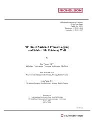
Thome, Richards, Wise, “ ‘O’ Street <strong>Anchored</strong> Precast Lagging and Soldier Pile <strong>Retaining</strong><br />
<strong>Wall</strong>” Contemporary Solutions to Land Mass Stabilization, IX Great Lakes Geotechnical<br />
Geoenvironmental Conference, Dayton, Ohio, May 11, 2001