Post-Tensioned Stabilization of Roy Inks Dam - Nicholson ...
Post-Tensioned Stabilization of Roy Inks Dam - Nicholson ...
Post-Tensioned Stabilization of Roy Inks Dam - Nicholson ...

Create successful ePaper yourself
Turn your PDF publications into a flip-book with our unique Google optimized e-Paper software.
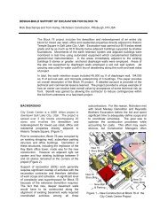
POST-TENSIONED STABILIZATION OF ROY INKS DAMJohn S. Wolfhope, P.E.Project ManagerFreese and Nichols, Inc.jsw@freese.comJerome W. Scanlon, P.E.AssociateFreese and Nichols, Inc.jws@freese.comGregor ForbesProgram ManagerLower Colorado River Authoritygforbes@lcra.orgRoger A. BaldwinProject Executive<strong>Nicholson</strong> Constructionrbaldwin@nicholson-rodio.comABSTRACT<strong>Roy</strong> <strong>Inks</strong> <strong>Dam</strong> (<strong>Inks</strong> <strong>Dam</strong>) is a high hazard, concrete gravity dam located on theColorado River near Burnet, Texas. The dam, constructed from 1936 to 1938, isowned and operated by the Lower Colorado River Authority (LCRA). During theLCRA <strong>Dam</strong> Modernization Program, the extreme flood events were reevaluatedfor the Highland Lakes <strong>Dam</strong>s. As a result, <strong>Inks</strong> <strong>Dam</strong> was found to be subject to amore severe loading condition than was considered in the original design. Thedam’s stability was analyzed under the new loading conditions and stabilizationimprovements were designed to protect the 880 feet long, uncontrolled, ogeeshapedspillway.Construction improvements to the dam included removal <strong>of</strong> the top lift <strong>of</strong> thespillway, construction <strong>of</strong> a reinforced concrete stressing beam, installation <strong>of</strong>forty-six 24-strand (1000 kip) post-tensioned anchors, and reconstruction <strong>of</strong> thecrest <strong>of</strong> the dam. The project also included an 18-inch pipeline penetrationthrough the dam to relocate an existing USFWS Fish Hatchery water supply line.This paper provides an overview <strong>of</strong> the challenges presented to the design teamdue to the unique nature <strong>of</strong> this project and the existing condition <strong>of</strong> the structure.It also presents a discussion <strong>of</strong> the construction and addresses how lessonslearned from previous post-tensioned spillway anchoring projects wereincorporated.
In the early 1990s the LCRA and Freese and Nichols, Inc. completed apreliminary study that determined four <strong>of</strong> the six Highland Lakes <strong>Dam</strong>s neededimprovements to meet modern design standards. As a result <strong>of</strong> that study, theLCRA began a $50 million, 15-year program to perform detailed investigations,design modernization improvements, and complete construction <strong>of</strong> improvementsfor the four dams. Risk analysis indicated that the flood wave resulting from afailure <strong>of</strong> <strong>Inks</strong> <strong>Dam</strong> would endanger at least 46 lives and would cause damagesin excess <strong>of</strong> $16 million dollars. <strong>Inks</strong> <strong>Dam</strong> was the third <strong>of</strong> the four dams to bemodernized, with the modernization <strong>of</strong> Alvin Wirtz <strong>Dam</strong> completing in 1998,Buchanan <strong>Dam</strong> in 2000, and <strong>Inks</strong> <strong>Dam</strong> in 2001. The remaining dam, Tom Miller<strong>Dam</strong>, is currently in the final design stages with construction scheduled for 2002through 2003.Figure 2 - Aerial Photograph <strong>of</strong> <strong>Roy</strong> <strong>Inks</strong> <strong>Dam</strong> (looking upstream)DESIGN OF MODERNIZATION IMPROVEMENTSFreese and Nichols designed the improvements and provided construction phaseservices for the modernization <strong>of</strong> <strong>Inks</strong> <strong>Dam</strong>. Other members <strong>of</strong> the Freese andNichols design team included Trinity Engineering/Kleinfelder, Hill CountryEnvironmental, and GeoSystems, Inc.The Team’s design evaluations included field investigations, installation <strong>of</strong>monitoring instrumentation, geotechnical drilling, laboratory testing, structuralsurveys, and visual inspections including detailed mapping <strong>of</strong> concrete cracks.Detailed design analyses were completed using conventional overturning andsliding stability analyses and included a physical hydraulic modeling programconducted at the Utah Water Research Laboratory (UWRL). From a macrostructuralperspective, the analyses indicated that the spillway and non-overflowsections <strong>of</strong> the dam were stable against sliding for all flood events. However,
overturning stability concerns were identified for the spillway section at floodevents greater than, or equal to, the 500-year flood. Preliminary designalternatives included stabilizing the dam using high capacity, multiple-strand,post-tensioned anchors, large numbers <strong>of</strong> lower capacity post-tensionedanchors, or mass gravity concrete overlays. High capacity, multiple-strand, posttensionanchors were determined to be the most cost-effective solution forstabilization the dam and were selected for final design.DESIGN CHALLENGESThe selected stabilization approach was successfully demonstrated for LCRAduring the stabilization <strong>of</strong> Alvin Wirtz and Buchanan <strong>Dam</strong>s. Lessons learned onthe previous two dams were applied during the design and construction <strong>of</strong> theanchors for <strong>Inks</strong> <strong>Dam</strong>. These lessons learned are discussed later in this paper.However, <strong>Inks</strong> <strong>Dam</strong> presented several design challenges that made this projectunique. The configuration <strong>of</strong> the spillway and rock outcropping at the left bankresulted in a cross section that varies substantially and a discharge that includessignificant three-dimensional hydraulic effects. The challenge <strong>of</strong> making a goodestimate <strong>of</strong> the hydrodynamic forces on the spillway was accomplished throughthe UWRL hydraulic modeling program.Detailed crack mapping revealed the spillway was severely cracked in the upperlifts and the concrete was deteriorating. Visual observations <strong>of</strong> the drilling coresand laboratory test data indicated that the concrete was <strong>of</strong> poor quality with somehoneycombing and little or no bond between many <strong>of</strong> the lift joints. Furthermore,the top ten feet <strong>of</strong> the spillway had lower unit weights and compressive strengthsthan the rest <strong>of</strong> the structure. Finally, significant leakage was observed throughseveral <strong>of</strong> the lift joints across the entire length <strong>of</strong> the spillway, especially at thefirst lift joint below the crest.The design <strong>of</strong> the post-tension system required careful consideration fortransferring post-tension anchoring forces into the structure. The design teamwas faced with a challenging question: How do you take large point loads andtransfer them into a structure comprised <strong>of</strong> irregularly fractured, poor qualityconcrete blocks? The design team developed an innovative approach using apractical solution. The simplest approach to stabilizing the structure would be tojust clamp all the pieces together and hold the structure to the foundation below.Figure 3 shows the design teams simple stabilization concept. We knew whatwe wanted to do, but the challenge was how to do it.
Figure 3 – <strong>Stabilization</strong> ConceptIn a brain storming session, the design team developed the concept <strong>of</strong> a highlyreinforced concrete stressing beam that acts as the top <strong>of</strong> the clamp to bring thepieces <strong>of</strong> the dam together. Figure 4 shows the developed design approach.Additional crack mapping was conducted to characterize the concrete crackingand the existing construction documentation was researched. Once all theinformation was gathered from historic data, visual inspections, and laboratoryanalyses, the final design was completed for the reinforced concrete stressingbeam and the high capacity, multiple-strand, post-tensioned anchor system.Strict qualification requirements were developed for the bidders to help ensurethat a qualified contractor was selected.Figure 4 - Section <strong>of</strong> repair methodology
CONSTRUCTION CHALLENGESConstruction <strong>of</strong> the stabilization improvements also presented several uniquechallenges. The work was performed on a constant level lake with no freeboardin the midst <strong>of</strong> an environmentally sensitive area. The left banks <strong>of</strong> the lake arewithin a state park accessible to the public. The United States Fish and WildlifeService (USFWS) operates a fish hatchery immediately downstream <strong>of</strong> the damand depends on <strong>Inks</strong> Lake for its supply <strong>of</strong> fresh water within strict water qualitytolerances. Numerous high-end homes are present on top <strong>of</strong> the bluffsoverlooking the dam.Physical constraints for construction included difficult site access, the proximity <strong>of</strong>high voltage power lines, and a small space-constrained working area. Themajority <strong>of</strong> the staging area for construction activities was the top fifteen feet <strong>of</strong>the spillway. The contractor, <strong>Nicholson</strong> Construction, only had access to thedam from one side <strong>of</strong> the spillway, and that access was only wide enough for onevehicle to pass at a time. Additionally, the side <strong>of</strong> the spillway that wasaccessible had a 24” siphon pipe crossing the crest <strong>of</strong> the spillway providingfresh, untreated water to the USFWS fish hatchery. Part <strong>of</strong> the project scopewas to replace the existing siphon with a gravity line to reduce maintenance andoperating costs for the USFWS and to remove this obstruction from the top <strong>of</strong> thedam. Due to the location <strong>of</strong> the pipeline and its obstruction to spillway access, ithad to be removed early in the construction schedule. In order to remove thesiphon, the USFWS required the contractor to provide the fish hatchery with acontinuous supply <strong>of</strong> fresh water up to 3,000 gallons per minute without anydown time greater than four hours. The task <strong>of</strong> installing the new USFWSwaterline included an 18-inch pipeline penetration through the dam. Thecontractor installed a specially designed skiff box on the upstream side <strong>of</strong> thedam to accommodate drilling a 22” diameter hole horizontally through thespillway. The skiff box allowed for the proper installation <strong>of</strong> a section <strong>of</strong> thepipeline and the intake. A specific grout mix design was developed by thecontractor to guarantee sealing the pipeline and the existing cracks in thesurrounding weathered concrete structure. As if these conditions were notchallenging enough, shortly after the start <strong>of</strong> construction, the hydroelectricgenerator, which is the only means <strong>of</strong> passing normal water flow through <strong>Inks</strong><strong>Dam</strong>, needed unscheduled maintenance. This lead to a period <strong>of</strong> approximatelyfour months where all flows had to be passed over the spillway while constructionactivities were ongoing.To overcome the overall project access challenges, the LCRA obtained a permitfrom the Texas Department <strong>of</strong> Transportation for a temporary constructionentrance <strong>of</strong>f the state highway and the contractor constructed about a one-halfmile long access road to the crest <strong>of</strong> the dam. Due to the environmentalconcerns, this road had to be carefully constructed and was completely removedat the completion <strong>of</strong> the project. To provide the fresh water requirements <strong>of</strong> the
USFWS, the contractor installed a temporary pipeline from the river to the watersupply line for the hatchery, installed two submersible pumps, and provided anemergency generator to provide uninterrupted flow to the fish hatchery.To provide personnel and vehicular access to the work area on top <strong>of</strong> thespillway, the contractor installed a steel cable safety rail on the upstream side <strong>of</strong>the dam and an eight feet wide steel platform was cantilevered <strong>of</strong>f thedownstream face <strong>of</strong> the entire spillway. Figures 5 and 6 show the upstreamsafety rail and downstream work platform. Due to the access constraints,particular attention was dedicated to daily scheduling during anchor installation.This scheduling allowed the equipment to be setup efficiently on the spillway andto prevent interruption <strong>of</strong> daily activities.Figure 5 – Anchor Installation with Safety Rails and Platforms
Figure 6 – Downstream work platformThe design <strong>of</strong> the stressing beam was configured to accommodate the concretedemolition work and to provide a temporary work surface and access road for thecontractor on top <strong>of</strong> the spillway. Figure 7 shows the preparation <strong>of</strong> the spillwaycrest to allow for construction access. The contractor sequenced hisconstruction activities to accommodate the limited access. Demolition <strong>of</strong> thecrest started at the right end <strong>of</strong> the spillway (in the middle <strong>of</strong> the river) using atrencher, jack-hammers, and a lot <strong>of</strong> manpower. Material was removed from thework area along the crest <strong>of</strong> the dam and demolition proceeded towards the leftbank.Figure 7 - Construction access on the spillway crest
The reinforced concrete beam formwork included steel pipe imbedments forinstalling the post-tensioned, multiple-strand tendon anchors. These guidesleeves, which would become permanent after the beam concrete set up, had tobe carefully surveyed into place in order to maintain proper drilling alignment andto miss existing drain holes located at the base <strong>of</strong> the spillway. The constructionsequence for installation <strong>of</strong> the beam proceeded in the same manner as thedemolition, starting in the middle <strong>of</strong> the dam and working towards the left bank.A significant environmental concern for the LCRA and USFWS was preventingdebris or construction discharge from entering the river. To accommodate theLCRA’s strict environmental and water quality standards, the contractor utilized acustom made diverter-system on the drill rigs to discharge cuttings through steellines laid across the entire 880 ft <strong>of</strong> the dam. In some locations debris was blownover 1,000 ft into a temporary holding pond. As a secondary containment, thecontractor dewatered the flip bucket at the downstream toe <strong>of</strong> the dam and usedit as a catch basin for any falling construction debris. At normal tailwaterconditions, the flip bucket is covered with approximately 3 to 4 feet <strong>of</strong> water. Thecontractor used a series <strong>of</strong> sandbags and plastic sheeting to create a smallc<strong>of</strong>ferdam along the edge <strong>of</strong> the flip bucket. The debris was removed and thesurface <strong>of</strong> the dam was cleaned on a daily basis.When the hydroelectric plant was taken <strong>of</strong>f line, the LCRA designed,manufactured, and installed a flash board system along the upstream crest <strong>of</strong> thedam. The flash boards were designed to route normal flows and small floodevents around the active construction areas. LCRA’s manufacturing shopdeveloped an innovative design for the flash boards that allowed large sections<strong>of</strong> the system to be quickly raised or lowered as needed. A picture <strong>of</strong> the flashboards is provided in Figure 8.Figure 8 - Flash boards along crest <strong>of</strong> <strong>Inks</strong> <strong>Dam</strong>
One <strong>of</strong> the major construction challenges was replacing the concrete on the crest<strong>of</strong> the dam. The upstream and downstream edges <strong>of</strong> the repairs were unevendue to the partial demolition <strong>of</strong> the crest and an ogee shape that was constructedover 60 years ago. The hydraulic loading on the structure dictated that theconstruction documents specify tight construction tolerances. Adjustable metalforms were developed to match the existing concrete on both ends <strong>of</strong> the ogeeshaped crest.Based on the Wirtz <strong>Dam</strong> and Buchanan <strong>Dam</strong> anchoring projects, LCRA and FNIlearned that the most important aspects <strong>of</strong> the anchoring system include thequality <strong>of</strong> the materials, the cleanliness <strong>of</strong> the tendons in the anchoring zone, anextensive quality control and inspection program, and the uniform seating <strong>of</strong> thewedges. Considering each <strong>of</strong> these, the design team chose to install barestrands within corrugated sheathing, to use two stage grouting and doublecorrosion protection, to require adequate cleaning <strong>of</strong> strands, and required theuse <strong>of</strong> power seating for the gripping wedges. One <strong>of</strong> the biggest challengesfaced by the construction team was the installation <strong>of</strong> the 8-inch corrugatedsheathing for the corrosion protection <strong>of</strong> the anchors while maintaining a twostage grouted system. Installing this type <strong>of</strong> system requires a very delicatebalance <strong>of</strong> hydrostatic pressures in order not to collapse the corrugatedsheathing during installation, water testing and grouting. The contractordeveloped a specific procedure for the installation and grouting <strong>of</strong> the corrugatedpipes that permitted the successful performance <strong>of</strong> the anchors without impactingthe schedule. The contractor developed a custom power seating system toaccommodate longer wedge travel for the higher elongation tendons to avoidmultiple jack setups. The construction inspectors from FNI and LCRA closelymonitored the handling and cleaning <strong>of</strong> the materials along with an extensivequality control program established by the contractor.The final construction challenge, and risk to the contractor, was the constantthreat <strong>of</strong> flooding. As stated before, <strong>Inks</strong> Lake is a constant level lake with nomeans <strong>of</strong> passing flood waters other than the spillway on which the constructionwas occurring. Due to the threat <strong>of</strong> flooding, the construction contract wasdesigned such that the LCRA meteorological group would provide daily forecaststo the contractor and the contractor remained prepared at all times to removeequipment and personnel with as little as four hours notice. The contract alsoincluded a line item for standby time that would cover the cost <strong>of</strong> shutting downthe job for flooding events. The standby time provision in the contract documentsprovided a way for both LCRA and the contractor to quantify their risk duringconstruction. It also provided a fair manner for the contractor and LCRA to sharethe cost <strong>of</strong> such an event. Fortunately there were no major releases <strong>of</strong> waterover the spillway during construction. However, during the last month <strong>of</strong>construction the drainage basin received significant rainfall that broke a droughtand filled Buchanan Reservoir (located about 2 miles upstream <strong>of</strong> <strong>Inks</strong> <strong>Dam</strong>) towithin one foot <strong>of</strong> the crest <strong>of</strong> the emergency spillway. Within a matter <strong>of</strong> twoweeks, Buchanan Reservoir rose over ten feet to capture nearly 200,000 acrefeetfeet <strong>of</strong> floodwater.
SUMMARYThe owner, design team, and construction team worked together closelythroughout the project to develop innovative, yet practical, approaches toovercome the engineering and construction challenges presented by thisstructure. Construction documents were developed to address theconstructability issues and were structured to clearly identify the responsibilitiesand risks <strong>of</strong> both the owner and the contractor. The owner, contractor, andengineer partnered together during construction to overcome unforeseenobstacles. As a result <strong>of</strong> the team effort during design, and the successfulpartnering during construction, all <strong>of</strong> the challenges were overcome and theproject was completed under budget and ahead <strong>of</strong> schedule.