recent advances in large diameter diaphragm wall shafts
recent advances in large diameter diaphragm wall shafts
recent advances in large diameter diaphragm wall shafts
- No tags were found...

Create successful ePaper yourself
Turn your PDF publications into a flip-book with our unique Google optimized e-Paper software.
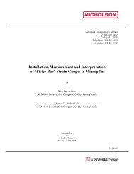
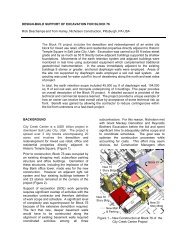
RECENT ADVANCES IN LARGE DIAMETER DIAPHRAGM WALL SHAFTSBenoit Virollet and Christian Gilbert, Soletanche-Bachy, Nantarre, France, andRick Deschamps, Nicholson Construction, Pittsburgh, PAOver the last 10 years the <strong>diameter</strong> of unbraced, unl<strong>in</strong>ed and unanchored circular<strong>shafts</strong> has grown dramatically <strong>in</strong> many parts of the world. This progress hastaken place through improvements <strong>in</strong>: construction methods; concrete rheology;and design capabilities. Excavation equipment has become more precise <strong>in</strong>terms of operator control and ability to correct alignment of digg<strong>in</strong>g elementslead<strong>in</strong>g to better alignment tolerances. Also contribut<strong>in</strong>g to the <strong>in</strong>creases <strong>in</strong> shaft<strong>diameter</strong>s is the evolution of design models. A better understand<strong>in</strong>g of soilstructure <strong>in</strong>teraction is be<strong>in</strong>g <strong>in</strong>corporated <strong>in</strong>to the analyses <strong>in</strong> terms of radial soilstresses and imposed loads on the shaft. This paper provides an overview of the<strong>recent</strong> progress made <strong>in</strong> circular shaft construction, the primary designconsiderations, and some <strong>in</strong>novative uses of efficient arc elements to developunsupported structures of other shapes. In addition, a summary of <strong>recent</strong>circular <strong>shafts</strong> constructed worldwide is provided.IntroductionCircular <strong>diaphragm</strong> <strong>wall</strong>s are constructed withthe same techniques that are used to constructplane <strong>wall</strong>s. They are built <strong>in</strong> situ under a drill<strong>in</strong>gfluid which stabilizes the excavation. Thesurround<strong>in</strong>g soil acts as the formwork forconstruct<strong>in</strong>g the concrete elements. A deeppanel trench is first excavated and stabilised bybentonite slurry. When excavated to the desireddepth, the re<strong>in</strong>forcement cage is <strong>in</strong>stalled andconcrete is tremie poured from the bottomdisplac<strong>in</strong>g the lighter bentonite. The stability ofthe trench is ensured by both the slurry and thearch<strong>in</strong>g of the soil on each side of the excavatedpanel. Accord<strong>in</strong>gly, the trench length is limited <strong>in</strong>order take advantage of the arch<strong>in</strong>g such thatthe <strong>diaphragm</strong> <strong>wall</strong> is built through a series of<strong>in</strong>dependent panels. "Water stops" and<strong>in</strong>terlock<strong>in</strong>g jo<strong>in</strong>ts are <strong>in</strong>stalled between panelsto ensure the water tightness of the <strong>wall</strong> andshear transfer between panels. Excavationbeg<strong>in</strong>s after the panels have achieved designstrength.The tools used to excavate the panels have arectangular shape, the length of which is on theorder of three meters (Figure 1). In practice, thepanels are generally made of three "bites," two<strong>in</strong>dependent bites with a connect<strong>in</strong>g smaller biteto control clamshell alignment. Therefore, thetypical panel lengths are approximately sevenmeters.The primary objective of this paper is to<strong>in</strong>troduce a cost effective construction approachfor support of excavation for circular <strong>shafts</strong> to abroader audience <strong>in</strong> the United States. Thetechniques described are used on a rout<strong>in</strong>ebasis and on a much greater scale <strong>in</strong> other partsof the world than are currently employed <strong>in</strong>North America. The technology is available <strong>in</strong>terms of equipment and methods of analysis,and there are several contractors with thecapacity to competitively bid and build this work.Accord<strong>in</strong>gly, it is hoped that designers willbecome familiar with the cost sav<strong>in</strong>gs andimproved certa<strong>in</strong>ty of execution with thisapproach relative to alternative systems such assunken caissons. These systems are especiallyattractive solutions to the EPA mandated CSOstructures be<strong>in</strong>g constructed <strong>in</strong> manycommunities.Basic Mechanical Behaviour of a CircularShapeCircular <strong>wall</strong>s are unique <strong>in</strong> that they cannotconverge freely when loaded externally.Consider a th<strong>in</strong> circular <strong>wall</strong> with a radius "R"that is subjected to an axisymmetrical pressure"p". The force equilibrium diagram shows that
pRR-uuN hdθdθ2N h dθ2pRdθpN hFigure 2 : Free body diagram of a circularsegment.Figure 1. Clamshell bucket.the reaction to the external pressure produces acompressive "hoop" force <strong>in</strong> the <strong>wall</strong> whichresists the tendency to converge. This isexpressed <strong>in</strong> Figure 2 where a free bodydiagram of a segment of <strong>wall</strong> is shown. Thehoop force , N h , is related to theapplied external pressure by the relationship :N h = p R (1)No extra support is required to balance theexternal forces. This is the reason why circular<strong>wall</strong>s are <strong>in</strong>herently stable provided the hoopforce does not exceed the limits of the materialproperties.A circumferential stiffness that relates theapplied pressure to the radial displacement, ∆R,can be def<strong>in</strong>ed as follows :P = E t ∆R / R 2 (2)"E" is Young’s modulus of r<strong>in</strong>g material and t isthe <strong>wall</strong> thickness. This relationship obta<strong>in</strong>ed fora r<strong>in</strong>g is used for the three dimensional circular<strong>wall</strong> under axisymmetrical pressure diagrams.Advantages of Circular Diaphragm WallsBased on the previous remarks, circular<strong>diaphragm</strong> <strong>wall</strong>s provide a lot of advantagescompared to plane <strong>wall</strong>s. They do not needsupports such as struts or tie-back anchors.Excavation works can be achieved quicklywithout complicated construction sequence orcoord<strong>in</strong>ation between the excavator and anchor<strong>in</strong>staller.Another benefit of the <strong>in</strong>herently stable circular<strong>diaphragm</strong> <strong>wall</strong>s lies <strong>in</strong> the much lessened needfor embedment to provide <strong>wall</strong> stability.Obviously other criteria for embedment must beconsidered, such as hydraulic stability (i.e.pip<strong>in</strong>g) and basal stability, but embedment formechanical stability of toe is unnecessary.It should also be recognized that as the hoopforce provides a stiff cont<strong>in</strong>uous support to the<strong>wall</strong>, the bend<strong>in</strong>g moment and shear force <strong>in</strong> the<strong>wall</strong> rema<strong>in</strong> generally small lead<strong>in</strong>g to "light"re<strong>in</strong>forcement ratios.Design of Circular Diaphragm WallsWall Alignment. The design of circular<strong>diaphragm</strong> <strong>wall</strong>s can require some unusualconsiderations which leads to a need for
detailed analyses. Tied to the analysis is arigorous control of construction tolerances. Thestabiliz<strong>in</strong>g hoop force produces a normalcompressive stress <strong>in</strong> the structure which islimited by the strength of the concrete. Thiscompressive stress is a function not only of thehoop force but also of the thickness of the r<strong>in</strong>g.As described previously, <strong>diaphragm</strong> <strong>wall</strong>s areconstructed by <strong>in</strong>dividual panels. These panelsare excavated with a rectangular shape shovel(Figure 1) such that it isn't possible to constructa perfect r<strong>in</strong>g (Figure 3). Moreover, theexcavation of the panels is done with a specifiedvertical tolerance, which makes the shape of the<strong>wall</strong> deviate further from the ideal geometry withdepth (Figure 3b). It is therefore essential to beable to control as much as possible theverticality of the excavat<strong>in</strong>g tool. This toleranceessentially depends on the experience of theoperator but also on the type of tool (mechanicgrab, hydraulic grab or hydrofraise), the type ofsoil (presence of boulders or not, stiffness of thesoil, etc.) and the quality control dur<strong>in</strong>gexcavation. This control is done through onboard <strong>in</strong>strumentation that allows for real timemeasurement of, and the ability to correct,deviation. Typical specified tolerance <strong>in</strong>deviation is <strong>in</strong> the order of 1% of the <strong>wall</strong> height,but 0.5% can be commonly achieved <strong>in</strong> practice.Regardless of the vertical tolerance achieved,the actual geometry will not be a perfect r<strong>in</strong>g.The common approach used to take <strong>in</strong>toaccount the "real" geometry is to <strong>in</strong>scribe anannulus <strong>in</strong>to the actual shape and calculate the<strong>wall</strong> loads neglect<strong>in</strong>g the concrete outside thisannulus. This method is very conservativebecause an <strong>in</strong>scribed annulus is not anecessary condition for stability because the<strong>wall</strong> is capable of resist<strong>in</strong>g bend<strong>in</strong>g and shearstresses. This is easily demonstrated byconsider<strong>in</strong>g self stable elliptical <strong>shafts</strong> where<strong>in</strong>an <strong>in</strong>scribed circle is not possible. An exampleis shown <strong>in</strong> Figure 4 of the Méricourt CSO shaft.Wall Shape. With elliptical <strong>shafts</strong> the externalsoil provides the required extra reaction toma<strong>in</strong>ta<strong>in</strong> stability. The <strong>wall</strong> sections experiencevary<strong>in</strong>g bend<strong>in</strong>g moments with location <strong>in</strong>addition to the compressive stresses becausethe radial stra<strong>in</strong>s/displacements are no longeruniform. The stresses result<strong>in</strong>g from the actualgeometry are evaluated by modell<strong>in</strong>g the <strong>wall</strong> asa horizontal beam <strong>in</strong> <strong>in</strong>teraction with an elasticplastic soil on one side only. This model givesthe normal forces, N, and the bend<strong>in</strong>g moments,M, at each node. This model allows for theP3P2e = 0.5mL = 2.8mP4P1Φ <strong>in</strong>t = 16mP5P8P6P7(a)(b)Figure 3 : Shape of a circular <strong>diaphragm</strong> <strong>wall</strong> <strong>in</strong>clud<strong>in</strong>g (la) grab geometry without deviation and(b) grab geometry and deviation.
assessment of specific concrete sections underthe vary<strong>in</strong>g state of stress. However, thisapproach is still conservative as it assumes thesoil pressure is constant. In reality, the soilpressure decreases with radial stra<strong>in</strong> thusreduc<strong>in</strong>g the bend<strong>in</strong>g moment. Other moresophisticated methods exist such as f<strong>in</strong>iteelements models, which are capable of com<strong>in</strong>gcloser to the real system, but <strong>in</strong> practice aredifficult to carry out.pressure. The Ha<strong>in</strong> solution takes account ofthe surround<strong>in</strong>g soil but not the threedimensional effects. The factors of safety givenby these two cases generally lead to a lowerbound of the overall factor of safety.Wall Open<strong>in</strong>gs. Circular <strong>wall</strong>s are relatively“easy” to calculate as long as the outsideload<strong>in</strong>g is symmetrical. However, theassessment of their behaviour becomes moredifficult when asymmetry occurs. For example,the case of a circular <strong>wall</strong> with an open<strong>in</strong>g is athree dimensional problem. The presence ofopen<strong>in</strong>g affects the <strong>in</strong>ternal forces <strong>in</strong> the <strong>wall</strong>.Because the hoop stresses can no longer begenerated at the open<strong>in</strong>g level, force equilibriumis balanced by higher stresses be<strong>in</strong>g generatedon both sides of the open<strong>in</strong>g as shownschematically <strong>in</strong> Figure 5. This concentration <strong>in</strong>compressive stress also produces a zone ofvertical tension due to the distortional stra<strong>in</strong>s.Additionally, the panels adjacent to the open<strong>in</strong>gtend to be "softer" produc<strong>in</strong>g <strong>large</strong>r bend<strong>in</strong>gmoments <strong>in</strong> the r<strong>in</strong>g at open<strong>in</strong>g level.(3) Displacement =>Bend<strong>in</strong>g momentFigure 4. Elliptical unsupported CSO shaft atMéricourt, France.Wall Buckl<strong>in</strong>g. The high compressive hoopstresses that are generated must also beevaluated <strong>in</strong> terms of buckl<strong>in</strong>g. This check isdifficult to carry out as the problem is threedimensional and non-l<strong>in</strong>ear. Three dimensionalbecause the surround<strong>in</strong>g soil pressure varieswith depth and there is restra<strong>in</strong>t from the passivesoil stress below the base and from the capbeam. It is non-l<strong>in</strong>ear because loads on the <strong>wall</strong>vary with stra<strong>in</strong>/displacement of the <strong>wall</strong>.Fortunately, closed-form solutions weredeveloped for some simple but related casesand these allow the factor of safety aga<strong>in</strong>stbuckl<strong>in</strong>g to be estimated. Timoshenko and Gere(1961) solved the case of a cyl<strong>in</strong>der fixed at itsends under a uniform pressure. Ha<strong>in</strong> (1968)solved the case of a r<strong>in</strong>g <strong>in</strong> <strong>in</strong>teraction with anelastic soil on the exterior. The Timoshenkosolution takes <strong>in</strong>to account some of the threedimensional effects but not the vary<strong>in</strong>g soil(1) Compression(2) TensionFigure 5. Changes <strong>in</strong> stresses aroundopen<strong>in</strong>gs <strong>in</strong> <strong>wall</strong>.The stress conditions can be evaluated with atwo dimensional approach. The <strong>in</strong>creasedbend<strong>in</strong>g moment can be estimated by reduc<strong>in</strong>gthe hoop stiffness at the open<strong>in</strong>g level. Thereduction factor is a function of the <strong>diameter</strong> of
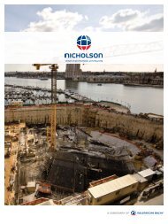
the <strong>wall</strong>, the <strong>diameter</strong> of the open<strong>in</strong>g and thecurvil<strong>in</strong>ear abscissa. The tension stress and theconcentration of hoop stress is estimated with aplane plate calculationProduc<strong>in</strong>g Other Shaped Walls with CircularArcsAlternatives to rectangular <strong>wall</strong>s can often beconstructed with circular arc segments therebyreduc<strong>in</strong>g or elim<strong>in</strong>at<strong>in</strong>g the need for anchorageor brac<strong>in</strong>g. Unsupported elliptical <strong>shafts</strong> (Figure4) require relatively small a / b ratio where a andb represent the long and the short axis,respectively. Another restriction is that thesurround<strong>in</strong>g ground must be stiff. As the waterand active earth pressures are approximatelythe same around the shaft, the hoop force mustbe greater along the long side than along theshort side. In order to balance all the forces, the<strong>wall</strong> has to mobilize a strong soil reaction alongthe short side and this reaction is mobilizedthrough <strong>wall</strong> displacement. In order to ma<strong>in</strong>ta<strong>in</strong><strong>wall</strong> stability these <strong>in</strong>duced displacements mustbe small enough so as not to generateexcessive bend<strong>in</strong>g moment.When the shapes of the <strong>wall</strong> componentsdeviate from cont<strong>in</strong>uous arcs, "fly<strong>in</strong>g" beams,abutment, or counterfort <strong>wall</strong>s can be build tosupport the hoop forces. These comb<strong>in</strong>edsystems have been successfully built <strong>in</strong> Europe,Asia and South America. The advantages of thisk<strong>in</strong>d of approach <strong>in</strong>clude the use of th<strong>in</strong>ner<strong>wall</strong>s, lighter re<strong>in</strong>forcement, and a <strong>large</strong> openexcavation area without the need for anchorage.Conversely, construction requires goodtolerance and attention to detail. Two examplesof bas<strong>in</strong>s compris<strong>in</strong>g circular arcs are shown <strong>in</strong>Figure 6.Example Project of Large Diameter ShaftThis example deals with a circular <strong>diaphragm</strong><strong>wall</strong> built by Soletanche-Bachy <strong>in</strong> NorthernEurope. The <strong>in</strong>ternal <strong>diameter</strong> of the <strong>wall</strong> is 90m(295 ft) with a thickness of 1.20m (4 ft). Thedepth of excavation is 28m (92 ft), 24m (79 ft) ofwhich is below the ground water level. The <strong>wall</strong>is permanent and without a secondary l<strong>in</strong><strong>in</strong>g.The specified maximum allowable deviation was+/-0.5% of the <strong>wall</strong> height.The primary results summarized <strong>in</strong> Figure 7show the heavily loaded <strong>wall</strong> system. Buckl<strong>in</strong>gwas an important issue as the average hoopstress was equal to 10.8MPa (1565 psi). The<strong>wall</strong> was also design to resist seismic load<strong>in</strong>g,which required that the panel jo<strong>in</strong>ts stay <strong>in</strong>compression.Seismic loads were computed with a threedimensions dynamic analysis assum<strong>in</strong>g the soilrema<strong>in</strong>ed <strong>in</strong> an elastic state and seismic<strong>in</strong>crements were superimposed to the staticcase.(a)(b)Figure 6. Multi-cell bas<strong>in</strong>s: (a) Hallium bas<strong>in</strong> with abutment <strong>wall</strong>s; (b) Lens-Lev<strong>in</strong> bas<strong>in</strong> with "fly<strong>in</strong>g"beams.
Maximum hoop force is at 23m depth and is equal to 12.5MN.Us<strong>in</strong>g Ha<strong>in</strong> model (2D non-l<strong>in</strong>ear approach), buckl<strong>in</strong>g force is approximately equal to 95EI/R 2 =75MN.Factor of safety on buckl<strong>in</strong>g is <strong>large</strong>r than 6.Inscribed annulus thickness without deviation is equal to 1.158m.Maximum deviation at 23m depth = 10.5cm.Inscribed annulus thickness with +/-10.5cm deviation is equal to 0.948m.Hoop stress at 23m depth without deviations is equal to 10.8MPa.Hoop stress at 23m depth with +/-10.5cm deviations is equal to 13.2MPa.Figure 7. Example Project Information, Excavated Shaft Photo, and Idealized Cross-SectionList of example <strong>large</strong> <strong>diameter</strong> and deep<strong>shafts</strong>A partial list of <strong>recent</strong> <strong>large</strong> <strong>diameter</strong> <strong>shafts</strong>constructed worldwide is summarized <strong>in</strong> Table 1.SummaryThis paper provided an overview of <strong>recent</strong><strong>advances</strong> <strong>in</strong> the design and construction ofcircular <strong>diaphragm</strong> <strong>wall</strong> systems. Thesesystems are especially attractive for the EPAmandated comb<strong>in</strong>ed sewer overflow conta<strong>in</strong>ersbecause they can be constructed to reta<strong>in</strong> <strong>large</strong>fluid volumes without any <strong>in</strong>ternal or externalsupport. Moreover, the systems are costeffective and provide higher certa<strong>in</strong>ty ofexecution dur<strong>in</strong>g construction relative tocompet<strong>in</strong>g systems such as sunken caissons.Additionally, elliptical and circular arc segmentscan also be used to construct efficient systemswith different shapes. The <strong>in</strong>corporation of thearc segments allows for th<strong>in</strong>ner <strong>wall</strong>s, lightersteel re<strong>in</strong>forcement and m<strong>in</strong>imal <strong>in</strong>ternal orexternal support.ReferencesHa<strong>in</strong>, H. H. (1968). Zur Stabilitat ElastischGebetteter Kreisr<strong>in</strong>ge Und Kreiszyl<strong>in</strong>derschalen,University of Hannover, Mitteilung Nr. 12.Timoshenko, S. and Gere, J. (1961) Theory ofElastic Stability, McGraw Hill, New York, 2 ndEdition.
Table 1. Recent Circular Shaft Projects Constructed Worldwide.Project’s nameDiameter(m)Depth(m)Thickness(m)Huang Pu Bridge, Ch<strong>in</strong>a 73.0 43.7 1.20Ville d’Avray Carrousel Shaft, France 7.8 63.0 1.02Viroflay Socatop Shaft, France 40.8 46.9 1.02Dubaï Palm STEP, EAU 76.2 22.0 1.00Beni Haroun STEP, Algeria 28.0 55.0 1.00HongKong Package 7 Tower, Ch<strong>in</strong>a 76.0 89.0 1.50Blackpool 2 Tanks, UK 36.0 46.044.01.001.00Ivry s/ Se<strong>in</strong>e SIAAP Shaft, France 22.5 56.5 1.52Bordeaux Pkg Gds Hommes, France 57.0 24.5 0.82Colombes GCN Interceptor, France 22.5 74.4 1.50Paris Pkg Harlay, France 31.0 52.0 0.80HongKong MRTC 501 Lantau, Ch<strong>in</strong>a 50.0 70.0 1.50Sangatte Shaft, France 58.0 21.0 1.00