series magnetic-latching established reliability to ... - Teledyne Relays
series magnetic-latching established reliability to ... - Teledyne Relays
series magnetic-latching established reliability to ... - Teledyne Relays

Create successful ePaper yourself
Turn your PDF publications into a flip-book with our unique Google optimized e-Paper software.
MAGNETIC-LATCHING<br />
ESTABLISHED RELIABILITY<br />
TO-5 RELAYS<br />
SPDT<br />
SERIES<br />
421<br />
SERIES<br />
DESIGNATION<br />
RELAY TYPE<br />
421 SPDT basic relay<br />
421D<br />
421DD<br />
SPDT relay with internal diode for coil transient suppression<br />
SPDT relay with internal diodes for coil transient suppression and polarity<br />
reversal protection<br />
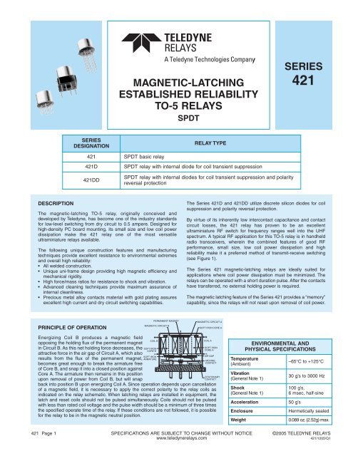
DESCRIPTION<br />
The <strong>magnetic</strong>-<strong>latching</strong> TO-5 relay, originally conceived and<br />
developed by <strong>Teledyne</strong>, has become one of the industry standards<br />
for low-level switching from dry circuit <strong>to</strong> 0.5 ampere. Designed for<br />
high-density PC board mounting, its small size and low coil power<br />
dissipation make the 421 relay one of the most versatile<br />
ultraminiature relays available.<br />
The following unique construction features and manufacturing<br />
techniques provide excellent resistance <strong>to</strong> environmental extremes<br />
and overall high <strong>reliability</strong>:<br />
• All welded construction.<br />
• Unique uni-frame design providing high <strong>magnetic</strong> efficiency and<br />
mechanical rigidity.<br />
• High force/mass ratios for resistance <strong>to</strong> shock and vibration.<br />
• Advanced cleaning techniques provide maximum assurance of<br />
internal cleanliness.<br />
• Precious metal alloy contacts material with gold plating assures<br />
excellent high current and dry circuit switching capabilities.<br />
The Series 421D and 421DD utilize discrete silicon diodes for coil<br />
suppression and polarity reversal protection.<br />
By virtue of its inherently low intercontact capacitance and contact<br />
circuit losses, the 421 relay has proven <strong>to</strong> be an excellent<br />
ultraminiature RF switch for frequency ranges well in<strong>to</strong> the UHF<br />
spectrum. A typical RF application for this TO-5 relay is in handheld<br />
radio transceivers, wherein the combined features of good RF<br />
performance, small size, low coil power dissipation and high<br />
<strong>reliability</strong> make it a preferred method of transmit-receive switching<br />
(see Figure 1).<br />
The Series 421 <strong>magnetic</strong>-<strong>latching</strong> relays are ideally suited for<br />
applications where coil power dissipation must be minimized. The<br />
relays can be operated with a short duration pulse. After the contacts<br />
have transferred, no external holding power is required.<br />
The <strong>magnetic</strong> <strong>latching</strong> feature of the Series 421 provides a “memory”<br />
capability, since the relays will not reset upon removal of coil power.<br />
PRINCIPLE OF OPERATION<br />
PERMANENT MAGNET<br />
MAGNETIC CIRCUIT B<br />
MAGNETIC CIRCUIT A<br />
SOFT IRON CORE A<br />
Energizing Coil B produces a <strong>magnetic</strong> field<br />
opposing the holding flux of the permanent magnet<br />
in Circuit B. As this net holding force decreases, the<br />
attractive force in the air gap of Circuit A, which also<br />
results from the flux of the permanent magnet,<br />
becomes great enough <strong>to</strong> break the armature free<br />
of Core B, and snap it in<strong>to</strong> a closed position against<br />
Core A. The armature then remains in this position<br />
upon removal of power from Coil B, but will snap<br />
SOFT IRON<br />
CORE B<br />
back in<strong>to</strong> position B upon energizing Coil A. Since operation depends upon cancellation<br />
of a <strong>magnetic</strong> field, it is necessary <strong>to</strong> apply the correct polarity <strong>to</strong> the relay coils as<br />
indicated on the relay schematic. When <strong>latching</strong> relays are installed in equipment, the<br />
latch and reset coils should not be pulsed simultaneously. Coils should not be pulsed<br />
with less than rated coil voltage and the pulse width should be a minimum of three times<br />
the specified operate time of the relay. If these conditions are not followed, it is possible<br />
for the relay <strong>to</strong> be in the <strong>magnetic</strong> neutral position.<br />
COIL B<br />
SOFT IRON<br />
ARMATURE<br />
COIL A<br />
SOFT IRON<br />
CORE A<br />
AIR GAP<br />
MOVING<br />
CONTACT<br />
STATIONARY<br />
CONTACT<br />
ENVIRONMENTAL AND<br />
PHYSICAL SPECIFICATIONS<br />
Temperature<br />
(Ambient)<br />
Vibration<br />
(General Note 1)<br />
Shock<br />
(General Note 1)<br />
Acceleration<br />
Enclosure<br />
Weight<br />
–65°C <strong>to</strong> +125°C<br />
30 g’s <strong>to</strong> 3000 Hz<br />
100 g’s,<br />
6 msec, half-sine<br />
50 g’s<br />
Hermetically sealed<br />
0.089 oz. (2.52g) max.<br />
421 Page 1 SPECIFICATIONS ARE SUBJECT TO CHANGE WITHOUT NOTICE ©2005 TELEDYNE RELAYS<br />
www.teledynerelays.com<br />
421/1205/Q1
SERIES 421<br />
GENERAL ELECTRICAL SPECIFICATIONS (–65°C <strong>to</strong> +125°C unless otherwise noted) (Notes 2 & 3)<br />
Contact Arrangement<br />
Rated Duty<br />
Contact Resistance<br />
Contact Load Ratings (DC)<br />
(See Fig. 2 for other DC<br />
resistive voltage/current ratings)<br />
Contact Load Ratings (AC)<br />
Contact Life Ratings<br />
Contact Overload Rating<br />
Contact Carry Rating<br />
1 Form C (SPDT)<br />
Continuous<br />
0.125 ohm max. before life; 0.225 ohm max. after life at 0.5A/28Vdc (measured 1/8" from header)<br />
Resistive: 0.5 Amp/28Vdc<br />
Inductive: 200 mA/28Vdc (320 mH)<br />
Lamp: 100 mA/28Vdc<br />
Low Level: 10 <strong>to</strong> 50 µA/10 <strong>to</strong> 50mV<br />
Resistive: 250 mA/115Vac, 60 and 400 Hz (Case not grounded)<br />
100 mA/115Vac, 60 and 400 Hz (Case grounded)<br />
10,000,000 cycles (typical) at low level<br />
100,000 cycles min. at all other loads specified above<br />
1A/28Vdc Resistive (100 cycles min.)<br />
Contact fac<strong>to</strong>ry<br />
Coil Operating Power 290 milliwatts typical at nominal rated voltage @ 25°C<br />
Operate Time<br />
Contact Bounce<br />
Minimum Operate Pulse<br />
Intercontact Capacitance<br />
Insulation Resistance<br />
1.5 msec max. at nominal rated coil voltage<br />
1.5 msec max.<br />
4.5 msec width @ rated voltage<br />
0.4 pf typical<br />
10,000 megohms min. between mutually isolated terminals<br />
Dielectric Strength Atmospheric pressure: 500 Vrms/60Hz 70,000 ft.: 125 Vrms/60Hz<br />
Negative Coil Transient (Vdc) 421D/421DD 1.0 max<br />
Diode P.I.V. (Vdc) 421D/421DD 100 min.<br />
DETAILED ELECTRICAL SPECIFICATIONS (–65°C <strong>to</strong> +125°C unless otherwise noted) (Note 3)<br />
BASE PART<br />
NUMBERS<br />
(See Note 8 for full P/N example)<br />
421-5<br />
421D-5<br />
421DD-5<br />
421-6<br />
421D-6<br />
421DD-6<br />
421-9<br />
421D-9<br />
421DD-9<br />
421-12<br />
421D-12<br />
421DD-12<br />
421-18<br />
421D-18<br />
421DD-18<br />
421-26<br />
421D-26<br />
421DD-26<br />
Coil Voltage (Vdc)<br />
Coil Resistance<br />
(Ohms ±10% @25°C)<br />
Coil Current (mAdc @25°C)<br />
(421DD Series only)<br />
Set & Reset Voltage<br />
(Vdc, Max.)<br />
Nom. 5.0 6.0 9.0 12.0 18.0 26.5<br />
Max. 6.0 8.0 12.0 16.0 24.0 32.0<br />
421/421D 61 120 280 500 1130 2000<br />
421DD (Note 4) 48 97 280 500 1130 2000<br />
Min. 78.0 45.8 25.7 19.6 13.4 11.2<br />
Max. 111.8 63.0 34.9 26.7 18.8 15.2<br />
421 3.5 4.5 6.8 9.0 13.5 18.0<br />
421D 3.7 4.5 6.8 9.0 13.5 18.0<br />
421DD 4.5 5.5 7.8 10.0 14.5 19.0<br />
PERFORMANCE CURVES<br />
(NOTE 2)<br />
dB<br />
TYPICAL RF PERFORMANCE<br />
0<br />
.1<br />
.2<br />
.3<br />
.4<br />
10<br />
1.92<br />
20<br />
1.22<br />
30<br />
1.07<br />
40<br />
1.02<br />
50<br />
1.01<br />
60<br />
1.00<br />
70 1.00<br />
.01 0.5 .1 .5 1.0<br />
INSERTION LOSS<br />
RETURN LOSS (VSWR)<br />
ISOLATION ACROSS CONTACTS<br />
FREQUENCY (GHz)<br />
FIGURE 1<br />
VSWR<br />
LOAD VOLTAGE (VDC)<br />
300<br />
250<br />
200<br />
150<br />
100<br />
50<br />
TYPICAL DC CONTACT RATING (RESISTIVE)<br />
0 0.1 0.2 0.3 0.4 0.5 0.6 0.7 0.8 0.9 1.0<br />
LOAD CURRENT (AMPS DC)<br />
FIGURE 2<br />
©2005 TELEDYNE RELAYS SPECIFICATIONS ARE SUBJECT TO CHANGE WITHOUT NOTICE 421 Page 2<br />
www.teledynerelays.com<br />
421/1205/Q1
SERIES 421<br />
OUTLINE DIMENSIONS<br />
CASE DETAIL<br />
.370<br />
(9.40)<br />
DIA. MAX.<br />
.335<br />
(8.51)<br />
DIA. MAX.<br />
.280 (7.11) MAX.<br />
+.002 (.05)<br />
.017 (.43) –.001 (.03)<br />
DIA.<br />
WIRE LEAD: .75 (19.05) MIN.<br />
PIN: .187 (4.75) ±.010 (.25)<br />
(See Note 6)<br />
TERMINAL LOCATIONS AND PIN NUMBERING (REF. ONLY)<br />
(Viewed from Terminals)<br />
.031 (.79)<br />
±.003 (0.08)<br />
.035 (.89)<br />
±.010 (0.25)<br />
.200 (5.08)<br />
±.010 (.25) DIA.<br />
36° ±3°<br />
TYP.<br />
9 1<br />
8<br />
2<br />
7<br />
6 4<br />
DIMENSIONS ARE SHOWN IN INCHES (MILLIMETERS)<br />
SCHEMATIC DIAGRAMS<br />
COIL B<br />
COIL A<br />
421<br />
COIL B<br />
COIL A<br />
GENERAL NOTES<br />
1. Relay contacts will exhibit no chatter in excess of 10 µsec or transfer in excess of 1<br />
µsec.<br />
2. “Typical” characteristics are based on available data and are best estimates. No<br />
on-going verification tests are performed.<br />
3. Unless otherwise specified, parameters are initial values.<br />
4. For reference only. Coil resistance not directly measurable at relay terminals due <strong>to</strong><br />
internal <strong>series</strong> diode, 421DD only.<br />
5. Unless otherwise specified, relays will be supplied with either gold-plated or soldercoated<br />
leads.<br />
6. The slash and characters appearing after the slash are not marked on the relay.<br />
7. Screened HI-REL versions available. Contact fac<strong>to</strong>ry.<br />
8.<br />
COIL B<br />
421D<br />
421DD<br />
COIL A<br />
SCHEMATICS ARE VIEWED FROM TERMINALS<br />
COIL A LAST ENERGIZED<br />
<strong>Teledyne</strong> Part Numbering System for T 2 R ® Established Reliability Relay<br />
ER 421 X M3 - 26 A / S Q<br />
Established Reliability<br />
Designa<strong>to</strong>r<br />
Relay Series<br />
Optional Ground Pin<br />
(See Appendix)<br />
Pad Option<br />
(See Appendix)<br />
<strong>Teledyne</strong> Part Numbering System for Military Qualified (JAN) <strong>Relays</strong><br />
Q= Solder Coated Leads<br />
G= Gold Plated Leads<br />
(Notes 5 and 6)<br />
S= 0.187" leads<br />
(Note 6)<br />
Screening and Reliability<br />
Level<br />
Coil Voltage<br />
J 421 X M - 26 P L<br />
Military (JAN)<br />
Designa<strong>to</strong>r<br />
Relay Series<br />
Optional Ground Pin<br />
(See Appendix)<br />
Pad Option<br />
(See Appendix)<br />
Screening and Reliability<br />
Level<br />
Terminal Variant<br />
P = 0.187"<br />
Coil Voltage<br />
JAN part number example is for reference only. Actual part number may not exist.<br />
421 Page 3 SPECIFICATIONS ARE SUBJECT TO CHANGE WITHOUT NOTICE ©2005 TELEDYNE RELAYS<br />
www.teledynerelays.com<br />
421/1205/Q1
Appendix A: Spacer Pads<br />
Pad designation and<br />
bot<strong>to</strong>m view dimensions<br />
Ø.150<br />
[3.81]<br />
(REF)<br />
“M4” Pad for TO-5<br />
Dim H<br />
MAX<br />
Height<br />
For use with the following:<br />
Dim. H<br />
Max.<br />
ER411T<br />
ER412, ER412D, ER412DD<br />
.295 (7.49)<br />
712, 712D, 712TN,<br />
RF300, RF310, RF320<br />
.300 (7.62)<br />
ER420, ER422D, ER420DD, 421,<br />
ER421D, ER421DD, ER422, ER422D, .305 (7.75)<br />
ER422DD, 722, 722D, RF341<br />
ER431T, ER432T,<br />
ER432, ER432D, ER432DD<br />
.400 (10.16)<br />
732, 732D, 732TN, RF303, RF313,<br />
RF323<br />
.410 (10.41)<br />
RF312 .350 (8.89)<br />
ER411, ER411D, ER411DD .295 (7.49)<br />
Dim H<br />
MAX<br />
ER431, ER431D, ER431DD .400 (10.16)<br />
RF311 .300 (7.62)<br />
“M4” Pad for TO-5<br />
RF331 .410 (10.41)<br />
“M4” Pad for Centigrid ® RF103 .420 (10.67)<br />
172, 172D .305 (7.75)<br />
ER114, ER114D, ER114DD,<br />
Dim H<br />
MAX<br />
J114, J114D, J114DD<br />
.300 (7.62)<br />
ER134, ER134D, ER134DD,<br />
J134, J134D, J134DD<br />
.400 (10.16)<br />
RF100 .315 (8.00)<br />
.156<br />
[3.96]<br />
(REF)<br />
“M9” Pad for Centigrid ® A150 .305 (7.75)<br />
122C, A152 .320 (8.13)<br />
Dim H<br />
ER116C, J116C .300 (7.62)<br />
MAX<br />
ER136C, J136C .400 (10.16)<br />
RF180 .325 (8.25)<br />
.256<br />
[6.5]<br />
(REF)<br />
Notes:<br />
1. Spacer pad material: Polyester film.<br />
2. To specify an “M4” or “M9” spacer pad, refer <strong>to</strong> the mounting variants portion of the part numbering<br />
example in the applicable datasheet.<br />
3. Dimensions are in inches (mm).<br />
4. Unless otherwise specified, <strong>to</strong>lerance is ± .010 (.25).<br />
5. Add 10 mΩ <strong>to</strong> the contact resistance show in the datasheet.<br />
6. Add 0.01 oz. (0.25 g) <strong>to</strong> the weight of the relay assembly shown in the datasheet.<br />
© 2008 <strong>Teledyne</strong> <strong>Relays</strong> SPECIFICATIONS SUBJECT TO CHANGE WITHOUT NOTICE
Appendix A: Spreader Pads<br />
Pad designation and<br />
bot<strong>to</strong>m view dimensions<br />
.300<br />
[7.62]<br />
.150<br />
[3.81]<br />
.100<br />
[2.54]<br />
.300<br />
[7.62]<br />
.300<br />
[7.62]<br />
.150<br />
[3.81]<br />
.370 [9.4]<br />
MAX SQ<br />
.200<br />
[5.08]<br />
“M” Pad 5/ 6/<br />
.390 [9.91]<br />
SQ<br />
.300<br />
[7.62]<br />
“M” Pad 7/ 8/<br />
.370 [9.4]<br />
MAX SQ<br />
.200<br />
[5.08]<br />
.100<br />
[2.54]<br />
.100<br />
[2.54]<br />
.100<br />
[2.54]<br />
.150<br />
[3.81]<br />
.150<br />
[3.81]<br />
.100<br />
[2.54]<br />
.100<br />
[2.54]<br />
Dim H<br />
MAX<br />
.370<br />
[9.4]<br />
MIN<br />
Dim H<br />
MAX<br />
.130<br />
[3.3]<br />
Dim H<br />
MAX<br />
.370<br />
[9.4]<br />
MIN<br />
Height<br />
Dim. H<br />
For use with the following:<br />
Max.<br />
ER411T, J411T, ER412, ER412D<br />
ER412DD, J412, J412D, J412DD .388 (9.86)<br />
ER412T, J412T<br />
712, 712D, 712TN .393 (9.99)<br />
ER431T, J431T, ER432, ER432D<br />
ER432DD, J432, J432D, J432DD .493 (12.52)<br />
ER432T, J432T<br />
732, 732D, 732TN .503 (12.78)<br />
ER420, J420, ER420D, J420D<br />
ER420DD, J420DD, ER421, J421<br />
.398 (10.11)<br />
ER421D, J421D, ER421DD<br />
J422D, ER422DD, J422DD, 722<br />
ER411T<br />
ER412, ER412D, ER412DD<br />
J412, J412D, J412DD<br />
.441 (11.20)<br />
712, 712D .451 (11.46)<br />
ER421, ER421D, ER421DD<br />
722, 732D<br />
.451 (11.46)<br />
ER431T<br />
ER432, ER432D, ER432DD<br />
.546 (13.87)<br />
732, 732D .556 (14.12)<br />
ER411, ER411D, ER411DD<br />
ER411TX<br />
.388 (9.86)<br />
ER412X, ER412DX, ER412DDX<br />
ER412TX<br />
712X, 712DX, 712TNX .393 (9.99)<br />
ER420X, ER420DX, ER420DDX<br />
ER421X, ER421DX, ER421DDX<br />
.398 (10.11)<br />
ER422X, ER422DX<br />
ER422DDX, 722X, 722DDX<br />
ER431, ER431D, ER431DD<br />
ER431TX<br />
.493 (12.52)<br />
ER432X, ER432DX, ER432DDX<br />
ER432TX<br />
“M” Pad 5/ 6/ 9/<br />
732X, 732DX, 732TNX .503 (12.78)<br />
Notes:<br />
1. Spreader pad material: Diallyl Phthalate.<br />
2. To specify an “M”, “M2” or “M3” spreader pad, refer <strong>to</strong> the mounting variants portion of the part number example<br />
in the applicable datasheet.<br />
3. Dimensions are in inches (mm).<br />
4. Unless otherwise specified, <strong>to</strong>lerance is ± .010” (0.25).<br />
5/. Add 25 mΩ <strong>to</strong> the contact resistance shown in the datasheet.<br />
6/. Add .01 oz. (0.25 g) <strong>to</strong> the weight of the relay assembly shown in the datasheet.<br />
7/. Add 50 mΩ <strong>to</strong> the contact resistance shown in the datasheet.<br />
8/. Add 0.025 oz (0.71 g) <strong>to</strong> the weight of the relay assembly shown in the datasheet.<br />
9/. M3 pad <strong>to</strong> be used only when the relay has a center pin (e.g. ER411M3-12A, 722XM3-26.)<br />
(800) 284-7007 • www.teledynerelays.com ♦ +44 (0) 1236 453124 • www.teledyne-europe.com © 2008 <strong>Teledyne</strong> <strong>Relays</strong><br />
.014<br />
[0.36]<br />
(REF)<br />
.014<br />
[0.36]<br />
(REF)
Appendix A: Ground Pin Positions<br />
Ø.200<br />
[Ø5.08]<br />
"Z" POSITION<br />
"X" POSITION<br />
"Z" POSITION<br />
Ø.200<br />
[Ø5.08]<br />
36°±3°<br />
"Y" POSITION<br />
45°±3°<br />
"Y" POSITION<br />
TO-5 <strong>Relays</strong>:<br />
ER411T, ER412, ER412T, ER420, ER421, ER422,<br />
ER431T, ER432, ER432T, 712, 712TN, 400H, 400K,<br />
400V, RF300, RF303, RF341, RF312, RF310, RF313,<br />
RF320, RF323<br />
TO-5 <strong>Relays</strong>:<br />
ER411, ER431, RF311, RF331<br />
.100<br />
[2.54]<br />
"Y" POSITION<br />
"W" POSITION<br />
.100<br />
[2.54]<br />
"Y" POSITION<br />
.100<br />
[2.54]<br />
"Z" POSITION<br />
"Z" POSITION<br />
.050<br />
[1.27]<br />
"X" POSITION<br />
.100<br />
[2.54]<br />
.100<br />
[2.54]<br />
"U" POSITION<br />
(ER116C and ER136C only)<br />
.100<br />
[2.54]<br />
Centigrid® <strong>Relays</strong>:<br />
RF180, ER116C, 122C, ER136C<br />
Centigrid® <strong>Relays</strong>:<br />
RF100, RF103, ER114, ER134, 172<br />
Indicates ground pin position<br />
Indicates glass insulated lead position<br />
Indicates ground pin or lead position<br />
depending on relay type<br />
NOTES<br />
1. Terminal views shown<br />
2. Dimensions are in inches (mm)<br />
3. Tolerances: ± .010 (±.25) unless otherwise specified<br />
4. Ground pin positions are within .015 (0.38) dia. of true position<br />
5. Ground pin head dia., 0.035 (0.89) ref: height 0.010 (0.25) ref.<br />
6. Lead dia. 0.017 (0.43) nom.<br />
© 2008 <strong>Teledyne</strong> <strong>Relays</strong> SPECIFICATIONS SUBJECT TO CHANGE WITHOUT NOTICE