GSM IV Intelligen Intelligen Intelligent Wireless Burglar Alarm ...
GSM IV Intelligen Intelligen Intelligent Wireless Burglar Alarm ...
GSM IV Intelligen Intelligen Intelligent Wireless Burglar Alarm ...

You also want an ePaper? Increase the reach of your titles
YUMPU automatically turns print PDFs into web optimized ePapers that Google loves.
functions 1、Record 10 secs voice alarm message. 2、Setting fixed time for set /recall alarm system in main machine. 1、Main monitor ,talk function. <strong>Alarm</strong> receiver talk with people who be with main machine. 4、Both 16 wireless alarm zone and 5 wired alarm zone set around alarm zone, 24 hrs zone, disabled zone to comply with kinds of place. 3、Main<br />
alarm zone (open/close) set easily to comply with kinds of wired detectors. 6、Outlet siren port. 5、Wired<br />
detectors work with main machine by couple learning code. 8、Make call send message to set/recall main machine from long distance. 9、Pre-set 5 for message 10、 5 numbers for call alarm. 7、<strong>Wireless</strong><br />
Pre-set 1 group alarm centre number and 1 group call alarm centre number. 12、 Notice user by sms when power is off. 13、 Control relay outlet when alarm out, to work together with power, video, etc. 14、 High quality dual or quad frequency <strong>GSM</strong>/GPRS wireless industrial module. 11、<br />
Internal backup battery in main machine. 16、 Whole wireless system. Install easily in garage, storage where fixed line 15、<br />
2.Speci<br />
Specification<br />
unreachable.<br />
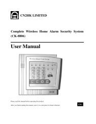
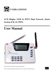
<strong>GSM</strong> <strong>IV</strong> <strong>Intelligen</strong>t t <strong>Wireless</strong> <strong>Burglar</strong> <strong>Alarm</strong> System<br />
User Manual<br />
Chapter 1<br />
our product,please read this manual before use it choosing for Thanks<br />
Chapter 1 Functions and Specification<br />
Chapter 2 mode of alarm zone<br />
circuital current:20mA 2、Supply power: DC 9V-12V 3. working temperature: -10℃- +55℃ 4、Support <strong>GSM</strong>900/1800Mhz (Optional: 850/1900MHz ) 1、standby<br />
mode:ASK 6、Receive frequency: 315/433 MHz 7、workable distance:100 m ( empty space) 5、Receive<br />
1
Chapter 3 Programming code settings<br />
1.mode<br />
remarksof alarm zone<br />
remarks:00<br />
00-15<br />
wireless alarm zone,16<br />
16-20<br />
wired zone,For each alarm<br />
zone,there are 3 kinds setting mode for different alarm message.<br />
A.)<br />
Arm Zone (only Active when the alarm in “Arm<br />
Arm” mode.<br />
B.)<br />
24 Hour (will Active at all conditions, even in “Disarm<br />
Disarm” mode)<br />
C.)<br />
Disabled Zone (Inactive Zone)<br />
Remarks: □ means one digit number,123456<br />
is default password<br />
assword,if user changed password, then,<br />
it will change 123456 into new password.<br />
Below 0-5 programming code for basic control(support call/sms<br />
) * Replay record voice<br />
1#□# Set arm/disarm<br />
system □=0 ;□=1 arm;<br />
;the system disarm<br />
2#□# Siren control<br />
;□=1 open;<br />
3#□# Monitor eg:sms:123456#1#0#<br />
close;□=1 open ;remarks:under talking status only<br />
4#□# Talking locale □=0<br />
close;□=1 open;remarks:under talking status only<br />
5#□# Relay control □=0 disconnect;□=1 connect;<br />
Below<br />
10-39<br />
programming code(sms only)<br />
10#User number The 1<br />
1st<br />
sms receiver eg:send message:123456#10#13800138000# ;means set number 15905090000 to be the 1st sms receiver, when alarm happen ,send message to this ★<br />
number,<br />
11#User number # The 2nd sms receiver receiver<br />
12#User 3rd 13#User 4th 14#User 5th sms 15#User number # The 1<br />
receiver<br />
message 123456#15#138001380005# ;set number 15905090005 to<br />
1st call number, when alarm happen, call this receiver number. eg:send<br />
16#User 2nd 17#User 3rd 18#User 4th 19#User number # The 5th call receiver<br />
2<br />
30#new password# Change password。 eg:send message:123456#30#123456# ;password change to be:123456<br />
31#□□□□<br />
□□□□#□□□□<br />
Set<br />
arm/disarm<br />
system at fixed time. update system time
;update system time eg:123456#31#2200#0800# ;set arm at 22:00 disarm at 08:00.<br />
33#□# Relay connect or not when alarm happen.<br />
no;□=1 yes :1<br />
39#□# Menu language □=0 English;□=1 Chinese;default:0 English ★ Below<br />
40-50<br />
settings for alarm centre(sms only)<br />
40#message<br />
centre<br />
number #□# For message centre □=0 set arm/dsiarm don’t notice;□=1 set arm/dsiarm system notice;<br />
eg: 123456#40#13800138000#0# ;set number 13800138000 to be message number, when alarm happen ,send message to this number.<br />
41#call centre default: number #□□□□<br />
□□□□#□ # For call centre □=0 set arm/dsiarm don’t notice;□=1 set arm/dsiarm system notice; default: 0 eg: 123456#41#13800138001#1234#0# ;set number 13800138001 to be call centre number. is main machine number. set arm/dsiarm system don’t<br />
when alarm happen, call this and send DTMF message.<br />
42#set system<br />
centre# For set system settings eg: 123456#42#13800138002# ;set number 15905091002 to be set system notice.<br />
number. When system is standby, call this number, after sound, then, be off line.<br />
43#recall system<br />
centre # For recall system centre eg: 123456#43#13800138003# ;set number 13800138003 to be recall system centre<br />
number. When system is recalled, call this number, after 3 sound, then, be off line. ★ Below<br />
50-65<br />
programming code for wireless zone(sms only) centre 50#□#zone name# For alarm zone 00<br />
mode. Message content is “door”<br />
51#□#zone #<br />
52#□# 53#□# 54#□# 55#□# zone name #<br />
eg: 123456#50#1#door #;wireless zone 00 is normal zone voice alarm<br />
01<br />
02<br />
3<br />
03<br />
04 For alarm zone 05<br />
mode of alarm zone; 2:zone name for message content 1mode of alarm zone:(details in chapter 2) □=0:disable ; □=1:normal arm zone; □=2:24 Hour zone 1:□ zone name: remarks:within 12 Chinese words、within 24 English words,default: wireless alarm 2.
56#□# 57#□# 58#□# 59#□# 60#□#zone #<br />
61#□# 62#□# 63#□# 64#□# 65#□# zone name #<br />
arm 06<br />
07<br />
08<br />
09 For 10<br />
11<br />
12<br />
13 For 14 For alarm zone 15<br />
Below<br />
66-70<br />
programming code for wired alarm zone(sms only)<br />
66#□#zone name#□# For wired alarm zone 16 1:□ alarm zone; 2:zone name for message content ★<br />
mode of act the wired alarm zone port.<br />
1mode of alarm zone:(details in chapter 2) □=0:disable ; □=1:normal arm zone; □=2:24 Hour zone<br />
2. zone name: 3:□<br />
12 Chinese words、within 24 English words,default: wired alarm remarks:within<br />
mode of action: □=0:shorted □=1:open default:0 3<br />
123456#66#1#hall#1# wired alarm zone 16 is normal zone voice alarm.message content:hall, port is open.<br />
67#□# 17 eg: 68#□# 18<br />
69#□# zone name#□# For wired alarm zone 19<br />
Chapter 4 Install Examples<br />
70#□# zone nam #□# For wired alarm zone 20<br />
and system description Install a infrared sensor for hall, a wireless door sensor for door, a wired door sensor 1.Hardware<br />
for strobe, a smoker sensor, 2 remote,1 sms receiver number: 1380013800,a call number:13800138001 remarks:sms receiver:send message to this receiver number when alarm out;call receiver: call this call number when alarm out.<br />
4<br />
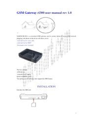
2. Install processing 1. Install accessories with main machine. Insert SIM card into card lock at back side of main machine.(remarks: support gsm network
card),connect with siren(siren be away from main machine at least 3m),fix antenna, power on(12V/1.5A power,internal“+”,outside“-”),STATUS orange flash slowly means it is searching network. around 40 seconds later ,it turn to green light, then, take next step. If can’t turn to green light, off ,then, check the sim card and antenna if ready. SIM<br />
Comply with remote and Put battery into wireless sensors and remote. Press RESET for 2 seconds. STATUS indicator turn to lasting red light.(main machine is learning sensors,20 later, sensors quit if can’t receive signal from main machine. Press RESET again to quit),install wireless 2.<br />
sensor, wireless door sensor, wireless smoker sensor, remote 1 and remote 2 one by one.(press emergency button of remote to comply with main machine). STATUS indicator infrared<br />
main machine will flash if sensor or remote be read. or , try again. 3. Record Press RECORD for 2 seconds, RECORD light on(main machine under record status for 10 seconds, 10 seconds later, it quit automatically.)speak with main machine to record till of<br />
light off. 4. Update system time<br />
message:123456#31# 5. Zone settings(details in chapter 2 and chapter 3) RECORD<br />
message:123456#50#1#hall alarm# 123456#51#1#door alarm# Send<br />
alarm# 123456#54#2#remote 123456#55#2#remote 2# 123456#66#1#strobe #1# 123456#53#2#gas<br />
Add user<br />
message:password#10#13800138000# Send message:password#15#13800138001# 7. Install ready, whole system status as below: 6.<br />
infrared <strong>Wireless</strong> zone alarm, <strong>Wireless</strong> door sensor Zone 01 Hall alarm、normal zone voice alarm<br />
gas sensor 02 Gas alarm、24hr 1 03 1、24hr Remote 2 04 Remote 2、24hr Wired door sensor Zone 16 Strobe/normal zone voice alarm, open alarm <strong>Wireless</strong><br />
Sms 0 Send message out when alarm happen 15905090001 Call receiver 0 Call out when alarm happen 15905090000<br />
3. System Test 1. System alarm test Press set button of remote, then, status be green light. then, depart the two parts of wireless door sensor. result:siren alarm out, send message to message receiver number. content “door alarm”. Make<br />
5<br />
to call receiver number, when receiver answer the call, it play the record voice.(press “*”repeat),press 1#0# to recall the system,press 2#0# close the siren(support call programming call
“di” 2. Long distance system control Call the main machine, after connect, then, heard 1 long sound of ,press password, end with #. Then, heard a long sound of “di”(password is correct, user monitor/control, code 1#-5#)<br />
3.<br />
,02… seconds later, sensors quit if can’t receive signal from main machine. Press RESET again to quit).the alarm zone number start from 00. then, 01 To re-arrange the zones: (0=no jumper, 1=High , 2=LOW) learning sensors,20<br />
must be 0022 2.) A0-A7 can be randomly e.g. you can assign 00012221 for zone 1 sensors 1.) D0-D3 00012220 2 you can assign 00012210 for zone 3 sensors<br />
3.) After setting the jumpers Please clear the main alarm all zone setiings by holding the reset button when powering on ......etc<br />
main unit 4.) then add the zone sensors by order after powering on, the green led light up, the<br />
the reset button for 2 sec, Then: press<br />
e.g.<br />
Chapter 5 Common Operation Introduction<br />
programming code 1#-5#),if heard 2 sound “di”(password is wrong, enter password again, it quit automatically if no correct enter into within 30 seconds.). 3. Trouble shooting support<br />
siren keep silent, please check if it is connected well. or mode of zone set to be silent If<br />
If can’t call out or send message out, please check if the value of SIM card is too low, or the signal is too weak. alarm. 1. How to add door sensor/infrared sensor/remote etc wireless detector Press RESET for 2 seconds. STATUS indicator turn to lasting red light.(main machine is<br />
1 1 2 Remote 2 (by pressing emergency button)<br />
3 /PIR 3 Zone 4 = trigger the door /PR zone 4 sensors. Zone<br />
then sensors will be recorded in order. ......<br />
6
2. delete wireless sensor/remote Send message:password#50#0# ;wireless detectors be delete of zone 00<br />
3. How to revive to default settings Press RESET,power on,till SATUS red light turn to orange flash light, all detectors of<br />
machine be delete. The password to be 123456。<br />
4. Long distance set the alarm system by phone Call the main machine, heard a long sound of “di”. Put password ,end with #.head a long main 5. How to re<br />
Chapter 6 <strong>Wireless</strong> accessories connection<br />
“di” “di” “di” into 1#1# ,then, a long sound again, then, quit the call. Remarks: all call programming , a long sound of means successes. 2 short means failure . How to re-define remote control pad Press RESET 5 seconds. STATUS indicator light turn to red light then turn to orange light. put “di”, of sound<br />
remarks:high level=1;1:low connection=0。<br />
level=2;no<br />
For Sensors:<br />
All Zone Jumpers D0-D3 must be set to 0022<br />
the 4 button one by one, the 1st one is emergency alarm button(if ok, the STATUS light will flash, it failed). 2nd button is recall system button, the 3rd one is set outside, the 4th one is set at home. Then, it quit. remarks:support 4 button remote only. press<br />
can be randomly A0-A7<br />
item<br />
you can assign 00012221 for zone 1 sensors<br />
00012220 2 you can assign 00012210 for zone 3 sensors ......etc e.g.<br />
2262 chip data lead pin connection<br />
D0 pin D1 pin D2 pin D3 pin<br />
Door sensor 0 0 2 2<br />
Infrared sensor 0 0 2 2<br />
Gas sensor 0 0 2 2<br />
Smoker sensor 0 0 2 2<br />
help 2 2 1 2<br />
Remote set Arm 2 2 2 1<br />
Remote recall 2 1 2 2<br />
Remote emergency call 2 2 1 2<br />
7