

Transactions A.S.M.E.
Transactions A.S.M.E.
Transactions A.S.M.E.

You also want an ePaper? Increase the reach of your titles
YUMPU automatically turns print PDFs into web optimized ePapers that Google loves.
370 TRANSACTIONS OF T H E A.S.M.E. JULY, 1941<br />
the downstream nose of one of the intake piers of each main unit<br />
for possible use should pumping w ith the units ever be resorted<br />
to for peak storage requirements during low flow. Both service<br />
units were provided with two piezometers of the W inter-Kennedy<br />
type. To prevent air pockets, all piping leading to the individual<br />
piezometer openings was placed w ith a continuous slope and copper<br />
piping was used to prevent corrosion. In the pipe tunnel<br />
beneath th e generator-room floor, a piezometer board with verti-<br />
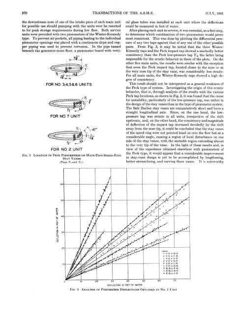
F i g . 2<br />
L o c a t i o n o f P e c k P i e z o m e t e r s o n M a i n - U n i t S p e e d - R i n g<br />
S t a y V a n e s<br />
( T a p s Y i a n d Y i . )<br />
cal glass tubes was installed at each unit where the deflections<br />
could be measured in feet of water.<br />
After placing each unit in service, it was essential, as a first step,<br />
to determine which combination of two piezometers would prove<br />
most consistent. This was done by plotting the differential pressure<br />
of any two taps against th at of any one of the other possible<br />
pairs. From Fig. 3, it may be noted th at the three Winter-<br />
Kennedy taps and the Peck im pact tap showed a markedly better<br />
consistency than the Peck low-pressure tap F 2, the latter being<br />
responsible for the erratic behavior in three of the plots. On the<br />
other five main units, the results were similar with the exception<br />
th at even the Peck im pact tap, located closer to the nose or at<br />
the very nose tip of the stay vane, was considerably less steady.<br />
For all main units, the W inter-Kennedy taps showed a high degree<br />
of consistency.<br />
This result should not be interpreted as a general weakness of<br />
the Peck type of system. Investigating the origin of this erratic<br />
behavior, th a t is, through analysis of the results with the various<br />
Peck tap locations, as shown in Fig. 2, it was found th at the cause<br />
for instability, particularly of the low-pressure tap, was rather in<br />
the design of the stay vanes than in the type of piezometer system.<br />
The Safe H arbor stay vanes are comparatively short and have a<br />
straight longitudinal axis. Since, on the one hand, the lowpressure<br />
tap was erratic in all units, irrespective of the shift<br />
upstream, and, on the other hand, the consistency and magnitude<br />
of deflection of the im pact tap increased decidedly by the shift<br />
away from the nose tip, it could be concluded th at the stay vanes<br />
of the speed ring were not pointed head on into the flow but at a<br />
considerable angle, causing a region of local disturbance on one<br />
side of the stay vanes, wTith the unstable region extending almost<br />
to the very tip of the vane. In the light of these results and, in<br />
view of the experience obtained elsewhere with piezometers of<br />
the Peck type, it would appear th a t a considerable improvement<br />
in stay-vane design is yet to be accomplished by lengthening,<br />
better streamlining, and curving these vanes. It is noteworthy<br />
F i g 3<br />
A n a l y s i s o f P i e z o m e t e r D e f l e c t i o n s O b t a i n e d a t N o. 2 U n i t


