

Transactions A.S.M.E.
Transactions A.S.M.E.
Transactions A.S.M.E.

Create successful ePaper yourself
Turn your PDF publications into a flip-book with our unique Google optimized e-Paper software.
406 TRANSACTIONS OF T H E A.S.M.E. JULY, 1941<br />
runner blades, represent a valuable contribution in connection<br />
with the design of the adjustable-blade-propeller turbine, whether<br />
of the T erry type or of the usual K aplan adjustable-bladepropeller<br />
turbine.<br />
There is one factor, however, which the author does not mention,<br />
but which does have an effect on the net hydraulic moment<br />
acting on runner blades, and th at is the centrifugal force acting<br />
on the blades.<br />
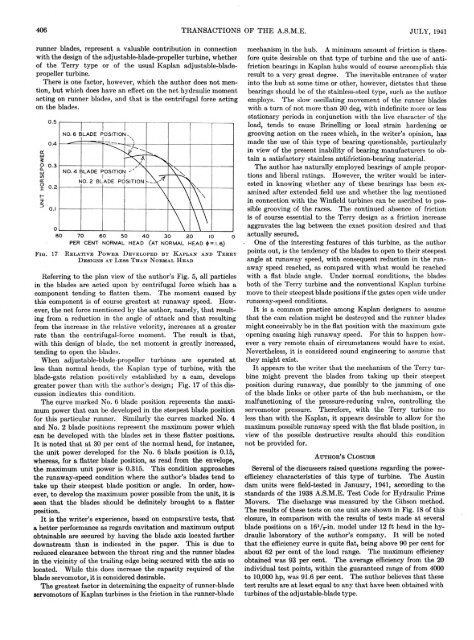
F i g . 17<br />
R e l a t i v e P o w e r D e v e l o p e d b y K a p l a n a n d T e r r y<br />
D e s ig n s a t L e s s T h a n N o r m a l H e a d<br />
Referring to the plan view of the author’s Fig. 5, all particles<br />
in the blades are acted upon by centrifugal force which has a<br />
component tending to flatten them . The m om ent caused by<br />
this component is of course greatest a t runaw ay speed. However,<br />
the net force mentioned by the author, namely, th a t resulting<br />
from a reduction in the angle of attack and th a t resulting<br />
from the increase in the relative velocity, increases at a greater<br />
rate than the centrifugal-force moment. The result is that,<br />
with this design of blade, the net mom ent is greatly increased,<br />
tending to open the blades.<br />
When adjustable-blade-propeller turbines are operated at<br />
less than normal heads, the K aplan type of turbine, w ith the<br />
blade-gate relation positively established by a cam, develops<br />
greater power than with the author’s design; Fig. 17 of this discussion<br />
indicates this condition.<br />
The curve marked No. 6 blade position represents the maximum<br />
power th a t can be developed in the steepest blade position<br />
for this particular runner. Similarly the curves m arked No. 4<br />
and No. 2 blade positions represent the maximum power which<br />
can be developed with the blades set in these flatter positions.<br />
I t is noted th at at 30 per cent of the norm al head, for instance,<br />
the unit power developed for the No. 6 blade position is 0.15,<br />
whereas, for a flatter blade position, as read from the envelope,<br />
the maximum unit power is 0.315. This condition approaches<br />
the runaway-speed condition where the author’s blades tend to<br />
take up their steepest blade position or angle. In order, however,<br />
to develop the maximum power possible from the unit, it is<br />
seen th a t the blades should be definitely brought to a flatter<br />
position.<br />
I t is the w riter’s experience, based on comparative tests, th at<br />
a better performance as regards cavitation and maximum output<br />
obtainable are secured by having the blade axis located farther<br />
downstream than is indicated in the paper. This is due to<br />
reduced clearance between the throat ring and the runner blades<br />
in the vicinity of the trailing edge being secured with the axis so<br />
located. While this does increase the capacity required of the<br />
blade servomotor, it is considered desirable.<br />
The greatest factor in determining the capacity of runner-blade<br />
servomotors of Kaplan turbines is the friction in the runner-blade<br />
mechanism in the hub. A minimum amount of friction is therefore<br />
quite desirable on th a t type of turbine and the use of antifriction<br />
bearings in K aplan hubs would of course accomplish this<br />
result to a very great degree. The inevitable entrance of water<br />
into the hub at some time or other, however, dictates th at these<br />
bearings should be of the stainless-steel type, such as the author<br />
employs. The slow oscillating movement of the runner blades<br />
with a turn of not more than 30 deg, with indefinite more or less<br />
stationary periods in conjunction with the live character of the<br />
load, tends to cause Brinelling or local strain hardening or<br />
grooving action on the races which, in the writer’s opinion, has<br />
made the use of this type of bearing questionable, particularly<br />
in view of the present inability of bearing manufacturers to obtain<br />
a satisfactory stainless antifriction-bearing material.<br />
The author has naturally employed bearings of ample proportions<br />
and liberal ratings. However, the writer would be interested<br />
in knowing whether any of these bearings has been examined<br />
after extended field use and whether the lag mentioned<br />
in connection with the Winfield turbines can be ascribed to possible<br />
grooving of the races. The continued absence of friction<br />
is of course essential to the Terry design as a friction increase<br />
aggravates the lag between the exact position desired and that<br />
actually secured.<br />
One of the interesting features of this turbine, as the author<br />
points out, is the tendency of the blades to open to their steepest<br />
angle a t runaway speed, with consequent reduction in the runaway<br />
speed reached, as compared with w hat would be reached<br />
with a flat blade angle. Under normal conditions, the blades<br />
both of the Terry turbine and the conventional Kaplan turbine<br />
move to their steepest blade positions if the gates open wide under<br />
runaway-speed conditions.<br />
I t is a common practice among K aplan designers to assume<br />
th at the cam relation might be destroyed and the runner blades<br />
might conceivably be in the flat position with the maximum gate<br />
opening causing high runaway speed. For this to happen however<br />
a very remote chain of circumstances would have to exist.<br />
Nevertheless, it is considered sound engineering to assume that<br />
they might exist.<br />
I t appears to the writer th at the mechanism of the Terry turbine<br />
might prevent the blades from taking up their steepest<br />
position during runaway, due possibly to the jamming of one<br />
of the blade links or other parts of the hub mechanism, or the<br />
malfunctioning of the pressure-reducing valve, controlling the<br />
servomotor pressure. Therefore, with the Terry turbine no<br />
less than w ith the Kaplan, it appears desirable to allow for the<br />
maximum possible runaw ay speed with the flat blade position, in<br />
view of the possible destructive results should this condition<br />
not be provided for.<br />
A u t h o r ’s C l o s u r e<br />
Several of the discussers raised questions regarding the powerefficiency<br />
characteristics of this type of turbine. The Austin<br />
dam units were field-tested in January, 1941, according to the<br />
standards of the 1938 A.S.M.E. Test Code for Hydraulic Prime<br />
Movers. The discharge was measured by the Gibson method.<br />
The results of these tests on one unit are shown in Fig. 18 of this<br />
closure, in comparison w ith the results of tests made at several<br />
blade positions on a 16V*-in. model under 12 ft head in the hydraulic<br />
laboratory of the author’s company. It will be noted<br />
th a t the efficiency curve is quite flat, being above 90 per cent for<br />
about 62 per cent of the load range. The maximum efficiency<br />
obtained was 93 per cent. The average efficiency from the 20<br />
individual test points, within the guaranteed range of from 4000<br />
to 10,000 hp, was 91.6 per cent. The author believes that these<br />
test results are a t least equal to any th at have been obtained with<br />
turbines of the adjustable-blade type.


