02-a Wet etching - Caltech Micromachining Laboratory
02-a Wet etching - Caltech Micromachining Laboratory
02-a Wet etching - Caltech Micromachining Laboratory

You also want an ePaper? Increase the reach of your titles
YUMPU automatically turns print PDFs into web optimized ePapers that Google loves.
Table 9.1 Compositions of<br />
Commonly Used Concentrated<br />
Aqueous Reagents<br />
Reagent Weight %<br />
HCI 37<br />
HF 49<br />
H2SO4' 98<br />
0 H)PO4 85<br />
HNO) 70<br />
HCIO4 70<br />
n CH)COOH 99<br />
,<br />
H2O2 .30<br />
L~ NH..OH 29<br />
0<br />
.(as NH))<br />
Table 9.2 Some Polishing Etches for Silicon<br />
0 ~~~~'-- Remarks --~~=~<br />
3 ml HF CP-4A. 80 ILm/min<br />
{l 5 ml HNO)<br />
l1<br />
3 ml CH)COOH<br />
lJ<br />
2 ml HF Planar etch. 5 ILm/min<br />
15 ml HNO)<br />
5 ml CH)COOH<br />
10 ml H2O2 0.7 11m/min. almost neutral etchant<br />
3.7 g NH4F ~<br />
0 ~ ml HF 0.3-0.4 ILm/min '",<br />
~ ~ ml KMnO4 (6%)<br />
0<br />
50 ml HF<br />
100 ml HNO,<br />
.110 ml CH,COOH<br />
3 g J~<br />
1]<br />
0 Table 9.3 Some Crystallographic Etches for Silicon<br />
0 I ml HF Dash etch, 8 h ,:/', .' :<br />
-' 3 ml HNO) / .<br />
Formulation<br />
Remarks<br />
..10 ml CH)COOH<br />
ri ImlHF Sirtletch.for(lll)silicon,5min<br />
lJ<br />
I ml crO) (5M in H2O)<br />
0 2 ml HF Secco etch. for (100) and (III) silicon. 5<br />
\ I ml K2Cr207 (0. 15M in H2O) min<br />
i<br />
60 ml HF Wright etch, for (100) and (III) silicon.<br />
30 ml HNO) 5 min, long shelf life<br />
r( 60 ml CH)COOH (glacial)<br />
U<br />
60 ml H2O<br />
30 ml solution of I g crO) in 2 ml<br />
n ~20<br />
L~ 2 g (CUNO)2 .3H2O<br />
.J 2 ml HF Silver etch, for faults in epitaxial layers<br />
I ml HNO)<br />
r -200 2 ml ml AgNO) HF (0.65M in H2O)<br />
For p-n JunctIon delineatIon, I mm<br />
.0 I ml HNO)
-"- --~<br />
Table 9.5 Etchants for Noncrystalline Films.<br />
Material Etchant Remark<br />
.<br />
m ~)<br />
~"', ~~;t;<br />
Si<strong>02</strong> 28 rol HF BHF. 1000-2500 A/min at 25°C<br />
170 ml H2O<br />
113 g N~F<br />
15 rol HF P-etch, 128 A/min at 25°C<br />
to rol HN03<br />
300 ml H2O<br />
I m1 BHF<br />
7 m1 H2O<br />
800 A/min<br />
BSG 1 m1 HF R-~tch, 300 A/min for 9 mole %<br />
100 m1 HN03 B2O3' 50 A/min for Si<strong>02</strong><br />
100 m1 H2O<br />
4.4 m1 HF S-etch. 750 A/rnin for 9 mole %<br />
100 inl HN03 B2O3' 135 A/min for Si<strong>02</strong><br />
100 rol H2O<br />
PSG 28- rol HF BHF, 5500 A/min for 8 mole %<br />
170 rol H2O P2O5<br />
113 g NH4F<br />
15 rol HF P-etch, 34,000 A/min for 16 mole<br />
10 ml HN03 % P2O5, 110 A/roin for Si<strong>02</strong><br />
300 ml H2O<br />
I ml BHF<br />
7 ml H2O<br />
800 A/min<br />
Si3N4 HF 140 A/min, CVD at I 100°C<br />
750 A/min. CVD at 9()()OC<br />
1000 A/min. CVD at 800°C<br />
28 ml HF BHF. 5-10 A/min<br />
170 ml H2O<br />
..I 13 g NH4F<br />
H3PO4 100 A/min at 180°C<br />
Polysilicon 6 ml HF 8000 A/min, smooth edges<br />
100 ml HN03<br />
40 ml H2O<br />
~ '. I ml HF 1500 A/min<br />
26 ml HN03 .<br />
33 ml CH3COOH<br />
'r<br />
SIPOS I ml HF 2000 A/min for 20% O2 film<br />
6 ml H2O<br />
10 ml NH4F (40%)<br />
Table 9.5 (Continued)<br />
Material Etchant Remark<br />
AI I rol Hcl 80°C, fine line, can be used with<br />
2 rol H2O gallium arsenide<br />
4 ml H3P04 350 Almin, fine line, will attack<br />
I rol HNO]<br />
gallium arsenide<br />
4 rol CH)COOH<br />
I rolH2O<br />
16-19 ml H]P04 1500-2500 A/min. ~ill attack ,<br />
I rol HNO] gallium arsenide J<br />
0-4 ml H2O ...~<br />
\<br />
0.1 M K2Br40, IILm/min. pH 13.6. no gas<br />
r 0.51 M KOH evolved during <strong>etching</strong><br />
0.6 M K]Fe(CN)6
U!<br />
's=-!,.- -<br />
r---<br />
"~ t' 1--, ' Table 9.5 (Continued)<br />
(] Material Etchant Remark<br />
; W 34 g KH2PO. 1600 Nmin, high resolution,<br />
13.4 g KOH resist mask can be used<br />
0 '33 g K)Fe(CN)6<br />
H2O to make I liter<br />
Pt 3 ml HCI Aqua regia, 20 lLm/min, precede<br />
0 I ml HNO) by a 30 s immersion in HF<br />
7 ml HCI 400-500 Nmin, 85°C<br />
I ml HNO)<br />
8 ml H2O<br />
0 Pd 1 ml HCI 1000 Nmin<br />
\0 ml HNO)<br />
\0 ml CH)COOH<br />
0 4 g KI 1 lLm/min, opaque, must be<br />
1 g 12 rinsed before visual inspection<br />
40 ml H2O<br />
0 .Listed in the order in which they are described in Section 9.1.6.<br />
0 Au 3 ml HCI -Aqua regia. 25-50 ILm/min<br />
-1 ml HNO)<br />
Ci 4 g KI 0.5-1 ILm/min. can be used with<br />
1 g 12 resist<br />
J<br />
40 ml H2O<br />
0 Ag I ml NH.OH 3600 Nmin. can be used with<br />
, I ml H2O2 resists. m~st be rinsed rapidly<br />
4 ml CH)OH after <strong>etching</strong><br />
C; Cr I ml HCI 800 Nmin. needs depassivation<br />
I ml glycerine<br />
,. I ml HCI 800 A/min. needs depassivation<br />
0: 9 ml saturated CeSO. solution<br />
j<br />
I,. I mi. I g NaOH in 2 ml H2O. 250-1000 Nmin, no<br />
3 ml, I g K)Fe(CN)6 in 3 ml depassivation, resist ma$k can<br />
0 H2O be used<br />
-Mo 5 ml HJPO. 0.5 lLm/min, re~ist mask can be<br />
-'-'; , 2 ml HNO) used<br />
,<br />
0::-..'.<br />
4 ml CH)COOH<br />
, 150 ml H2O .,<br />
5 ml H)PO. Polishing etch<br />
C: 3 ml HNO)<br />
2 ml H2O<br />
II g K)Fe(CN)6<br />
r: 10gKOH<br />
L-!<br />
150 ml H2O<br />
I ILm/min<br />
S25<br />
ri<br />
L<br />
n -'"<br />
i$r)~ "};",,'\;<br />
I ;1~fJct -$~<br />
-A .;;"-<br />
i ,\
:;"..~<br />
1;--:-1 '~<br />
i ~ l<br />
[J' ,<br />
0 FIGURE 8.10 C<br />
~ Determination of composition<br />
( I from triangular scale. (NorlJ<br />
mally, the interior lines will not<br />
be drawn on the diagram. This<br />
0 scale is shown moving counterclockwise.,<br />
Some diagrams<br />
use a clockwise scale.)<br />
0<br />
0<br />
D<br />
AB<br />
I J 100<br />
, v--'l -v JL_~<br />
fi,. 30% B 45% C 25% A<br />
tJ<br />
%Bn<br />
L l-r<br />
c:> i LI\&t\:<br />
0 \ rrtJ A'\ S~~~3 + 6~F =~ ~~-~~+ H~() + H2 I: '7J': ;<br />
) '(~ t(:1~.1<br />
: "f>" I :'fD~I~<br />
G<br />
I:I/~<br />
0 P, '
&~s t*c,k: ;]<br />
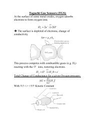
The H2SOc-H2O2-H2O System.<br />
j<br />
-1<br />
H2<strong>02</strong> .J<br />
~<br />
J<br />
}]<br />
H 0 250.<br />
2<br />
Flg.9.2 Isoetch curves for gallium arsenide (H2SO.:H2O2:H2O system). From Iida and<br />
Ito [15]. Reprinted with permission of the publisher, The Electrochemical Society, Inc. i<br />
J<br />
a<br />
a<br />
0<br />
The H3POc-H2O2-H2O System.<br />
0<br />
il<br />
1<br />
~o il<br />
30oC<br />
(100) 0<br />
\ U<br />
~ ~<br />
-0 i-l<br />
85 wt. % H3PO4 +- H3PO4 vol. % 30 wt. % H20s 0<br />
0<br />
Fig. 9,3 Isoetch curves for gallium arsenide (H]PO.: H2O2: H2O system). From Morl and<br />
Watanabe [17]. Reprinted with permission of the publisher. The Electrochemical Society,<br />
Inc. .<br />
Q<br />
i<br />
,. I<br />
"..:.",,; "<br />
UO!<br />
'\ j<br />
!
Defects delineated by <strong>etching</strong><br />
Precipitate with<br />
prismatic loops<br />
Plate-like<br />
precipitate with<br />
dislocations
New Journal of Physics 5 (2003) 100.1–100.28
, '., ...: Chemical ""~.:.:::'; ~ :'- ',...~;."': Etchin'g ,.;.~.-;:':..:-f.:. of ;:,~~~;~~~.-:..:i~~~:~.:::=~-~;;.;',::'-~:~,;'-:~:;.~ Silicon ..::~-'.. -~ ~..,;. --',~.: ~ ~.; ;..,.::::~~?~~~~~.<br />
, ; ."<br />
..-, -.; '-:-,,"':<br />
IV. Etching Technology ...'- ~:~Z~",<br />
.":, ~::'"~Z~tJ<br />
B, Schwartz _:".~.'~~".."(.<br />
..' ...<br />
Bell Laboratories, Murrau Hill, New JerBe'j 07974 :;';;'-:~.{~<br />
d H R bb ' .--; --<br />
an ,0 Ins:.~;'" i'~:<br />
:1'. .;<br />
Galamar Industries, Palo Alto, California 94304 .-',~ :.:";-:<br />
ABSTRACT<br />
, .-"."<br />
-.;"~.::; ~;<br />
.:~::;~k;;<br />
The <strong>etching</strong> of silicon in HNOa-HF based systems proceeds by a sequ.en- --.~ :,.-#~~~.<br />
tial oxidation-fo.11o",:ed-by-dissol~tion process. ~ ~ose composition ~~~ns 7 .:.~~;:.~::;;:':<br />
where the solution 15 very low m HNOa and nch m HF, the rate-limiting .' .: ~'~~.<br />
process .is the oxidation step. Conseq~ently, electro~ concen~ration, surface '- ~-~: ~t'<br />
,?rientatlon, crystal defects, and c~t,alYSIS by lower I?Xl.des ~f .nItrogen play .an -;::;.:1,<br />
lInportant role. In those composItIons where ~ 15 m 1imi~ su?ply, dis- :..~~"'-<br />
solution of the formed oxide is the rate-contro11mg step and diffusIon of the .::;.~.:<br />
complexing fluoride species is the important factor. Therefore, cr,:stal ori- :::.::<br />
entation and conductivity type independ.ence as well as hydrodynan1lc co~t;rol -);.;~,;'..<br />
are the consequences. In order to mearongfully select an <strong>etching</strong> COmI;>oSltlon ,; :'"-' --f:,<br />
to solve a specific processing problem, it is necessary to un.derstand this CO;m- .--""t.:-~~-:~<br />
position-mechanism interaction. Corollary with the mec~m under.standing, -,.; -.;.:~:~'~)J<br />
sample geometry effects have be~n follow~ .as a functIon of solution c«;,m- ., -;'.".;;<br />
position. The HF-HNO3-H20 solution coml?osltion pl~e h~ been characte~ '.::OJ:.[~:<br />
into various regions where the two haslC mechanlSms mteract and specific ,:,::;:'d:;~<br />
procesing utilization is shown. Similar results a~ shown fo~ the system HF- .:~..;.:i<br />
HNOa-HC2H3<strong>02</strong>. In addition, a number of particular <strong>etching</strong> problems .are ::!;':",,?<br />
posed, and solutions offered, that make. u~e of the~e composition characterl;U- :..,: ~'._~:. '.<br />
tions, a.nd show how one can use theIr Information to solve other practical .'. :.~-~~-;~<br />
processIng problems. ~';'"<br />
..-:. .,.,<br />
, ...~i:;,;j: i<br />
Most of the data on silicon <strong>etching</strong> that one can not controlled with respect to any partic.war c~ :-::~~:i, 1<br />
~<br />
find and kinetics the literature of the involve dissolution studies process of the (1-4). mechanisms There plane. means that Also, the the exposed dice were surfaces used contamed as. receIved, saw damage. which :-:',:;i-" :'~~.~:-!-"<br />
are a few examples of practical applications, but they All dice were etched three times, and each etch was ' -;.'. :--/<br />
deal primarily with crystallographic aspects of the performed in a fresh portion of the same solution. '-.. ;~;:<br />
<strong>etching</strong>, e.g., defect delineation (5) or anisotropic Since each <strong>etching</strong> period had been chosen to remov~ :.:::-::-1,;<br />
crystal plane <strong>etching</strong> (6). Because of the sophistication 4 to 6 mils from the specimen, it may be assumed that ;.; ~l::~<br />
of present-day silicon technology, it appears to be the work damage had been removed after the first : _.:~.::<br />
desirable to be able to control the geometrical aspects etch. The third--.etch-was p~rformed with a few ~:-- .~:.t-,=~of<br />
a silicon slice, e.g., from sharp, possibly peaked gramss=~ NaNQ;2~tO the ~~ssi-PJL ':-:.,:;'f;..,<br />
corners and edges to smooth and rounded edges and a lC u oses (1). er eac <strong>etching</strong> step, the '-:~'.~~~:;'.;,<br />
corners, merely by controlling the chemical <strong>etching</strong> sample was rins m istilled water, dried, and mea- .._",::;.::..~..<br />
environments. It would, therefore, seem appropriate sured for dimensional changes with a micrometer to '- ,~ ~:,~<br />
to present some d~ta on t,h.e geometrical effects ob- :t. 0.05 ~s, and then ~e geometry of the specimen -~J~;~ . '<br />
-served on the etchIng of silicon rectangular parallel- was exammed under a IDlcroscope. -~.:, ,O;i:,:.;<br />
e~ipeds in solutions of HNOa, HF,. and H2O with and Concentra~ed hydrofluoric acid, as normally SUPP1!ed. .:... "~-.~; ,<br />
without H~2H3<strong>02</strong>. 'I;'hese ob~ervatlons ~ere m~de ,at may vary m concentration from 48 to 52 weIght :~':'-':~"'~<br />
the same tiJ?e as t~ preVIously ~u~lished kinetics percent (w/o). SimnA1'ly, nitric acid may vary betwe81.~<br />
data were beIng obtain"ed (1,2), b';lt 1: 15 onlY,recently the limIts of 69 and 71%. In order to estab;1ish control~"iI!1<br />
that many requests for geometnc info~tio~ h~ve over the composition of the <strong>etching</strong> solutions, it was"':.:4=1'!~made<br />
us aware of the usefulness of disselDlnating necessary to standardize the stock -acids from which .;.~"'::~..<br />
these configurational data. the solutions were to be made, This was done by .~;f~<br />
In orde,!, ,to m.ake the picture more ~omplete, s°!De titrating samples of the acids against a standard sodium ;~:"~~:~1<br />
of the ongmal Is~-etch-rate figures will also be m- hydroxide solution. Potassium acid phthalate was used ;. .4<br />
cluded, for companson purposes, as the primary standard for the sodium hydroxide. .I<br />
~_. The bottle of hydrofluoric acid analyzed first at '<br />
p~<br />
Lxt'golmental Proced~re .49.25%, and this concentration was accordingly se- -;<br />
The technique used for the etchm~ an~ thlck~ess lected as the standard HF reagent concentration. All ..-<br />
monitoring has been adequatel~ descnbed m prevlo~s subsequent bottles of hydrofluoric acid were adjusted '.'"<br />
publications (1-3). However, m order to make thiS to 49.25 :t 0.05% by the addition of 60% HF or water.<br />
paper useful, we will have to repeat- some of. the as dictated by the chemical analysis, In a similar ."' ,<br />
experimental detail, but will stress only the sall~nt manner, the value 69.51 % HNOa was established as " '::.<br />
features of the sample and solution preparatIon the standard nitric acid concentration and all sub- .::':<br />
methods and h°v.: the geometric aspects were fo11o",:",ed. sequent stock bottles of nitric acid ~ere adj\,1s.ted to _:~ 1<br />
The sample dIce were rectangular parallelepIpeds this value :t. 0.05% by the appropnate addItIon of .<br />
~<br />
(0.125 X 0.125 X 0.<strong>02</strong>5 in. on side) cut from n-t~pe water or 90% HNOa. In a second series of experiments .<br />
silicon slices with resistivities about 2 {l-cm. The dice designed to cover a larger area of the composition . ~.<br />
were cut so that the large-area ~u,rfaces were along range, 90.45 :t. 0.05% HNOa and 59.75 :t 0.05% HF -.: j.<br />
the (111) plane while the remaInIng surfaces were were the standard reagents used. In a third series of .-~ '~':.f~<br />
.Electrochemical Society Active Member. experiments, glacial acetic acid was used as a ~uent, .:I.:~!~~_~i<br />
1 All of the daU used In this paper were obtained whfie the and the only water present was that found In the -.~<br />
authors were employed at Hughes Aircraft Company. original HNOs or HF reagents. ..;;.':-<br />
Key words: I1l1con, <strong>etching</strong>, geometry control. i' : =-"'( ,", ~<br />
1903 .'.":~';~,'~<br />
" ,.<br />
---,<br />
."c.~
"...-~-: 1804' .' -J. Electrochem. SoC.: SOLID-STATE SCIENCE AND TECHNOLOGY December<br />
,".:: , :." '- --.<br />
~_£~~~~, : ~ -.The <strong>etching</strong> was done in a Teflon beaker 1 in. in -: : ~<br />
."-:'~;'-.:.- -diameter and 2112 in. deep. Agitation was provided by<br />
~ ::.' an electric stirrer equipped with a polyethylene paddle. ;j<br />
,;;-=.~'~ The dice were etched one at a time in 10 cm3 of :! .6<br />
..,1:':~: '. solution, and duplicate results were obtained by re- ~<br />
~;:-~~' ,~'- peating the en~ire experiment. To quench the reaction ItJ<br />
-:.<br />
1:;'.:<br />
at the proper tIme, a large volume of water was poured<br />
into the beaker. The <strong>etching</strong> technique was later mod-<br />
~ 12<br />
:I:<br />
'::','!':;<br />
.;~.<br />
ified when the ~igher concentration reagent~ we:e<br />
used. Here the dIce were etched two at a tIme, In ~<br />
"j':. -20 cm3 of solution, while encased in a small perforated ~<br />
". ':. polyethylene basket. The basket and dice were agitated ~<br />
for the required time in the solution, then immersed z:<br />
in a beaker of cold water to quench the reaction. The I-<br />
agitating action consisted of approximately 150 vertical<br />
strokes per minute, with the <strong>etching</strong> jig rotated<br />
". betv.:een th~ thumb and middle finger as rapidly as 15 20 25<br />
possIble d~Ing the up and do":",n strokes.<br />
TIME (SECONDS)<br />
All etchIng was performed In a constant temperature<br />
(A)<br />
bath regulated at 25.00. =- 0.<strong>02</strong>.C. Unfortunately,<br />
.: .the heat transmission of polyethylene and Teflon is<br />
.~:<br />
i:';:<br />
so poor that the temperature of the bath could not be<br />
realized in the .etch solution, and even after long<br />
Vi<br />
=<br />
:';.:;: .periods of equilibration the maximum initial e~h ~ 12<br />
:::; ~J temperature was only 24.70.C. .AS; a further Ca:n-<br />
..,.;; ~ lequence of the poor heat transInlSSlOn of the <strong>etching</strong><br />
~<br />
z<br />
":":<br />
~.~~<br />
container, the more rapid etches were run under<br />
essentially adiabatic conditions.<br />
~<br />
(.) 8<br />
~~;;,::: It was realized early in the study that in some etch ~<br />
..:0,: .,<br />
':::',<br />
compositions the rate of attack on the die would be so<br />
high t~at if t~e specimen were left in the solution for ~ 4<br />
~:,.,,;.,~. one mlnute, eIther the sample would be etched away x:<br />
'.~:,,::.-i:Ompletely or it would be so thin that it would be. I-<br />
,:_.:' :j:' '. was very made difficult to choose to handle. etch For time this for reason each composition an attempt<br />
90 120 150<br />
:",-:..such that only 4 to 6 mils of material would be re- TIME (SECONDS)<br />
,4:::' moved. The etch rate was then linearly extrapolated (8)<br />
of "', ,' c L - loft d f t. f d .- II .<br />
:~;;.~';<br />
'.:, to tobtain 1 t... the 1 11 min t value. ted b The Fi justification 1 h th for h the F... 1 C hang - ~ rn ~n~.s peas a unc Ion 0 ,.<br />
~-.,: -:~.:, ..', .ex rapo a IO~ IS 1 us. ra y g. w ~re e.c ange posure time: (A) solution composed of 55% HF. 45% HNO3; (I)<br />
::". .In two sam.ple different thickness etch 15 composItIons. plotte;~ as a It fu~ctIon.of 15 qwte tlme.for posslble solution composed of 30% HF . 70% HH03.<br />
~:~-' .that for compositions where the etch rate is very high,<br />
~~,--'.the linear relation between the amount of material -The solution composition field was subdivided into<br />
-:,~:" removed and the time is not valid for the entire a number of evenly spaced points representing dif-<br />
.f ."..:.- minute, since the reaction is known to be strongly ferent compositions. The amounts of each reagent<br />
.~:j.:~:,: ~c exothermic and to proceed under adiabatic conditions. corresponding to each composition were then calc:-u-<br />
~';~,'. Nevertheless, it is believed that by limiting the etch lated, and the solutions were prepared by puttIng<br />
;~J,~;~ ~. time to minimize the effect of changes in experimental together the required amounts of reagents. The hydro-<br />
7;.:.:;; -: conditions, one could obtain numbers by linear extrap- fluoric acid was weighed out directly to =- O.Olg. but<br />
i",:~~ olation which are reasonably valid. The change in the weights of nitric acid and water were converted to<br />
~:~' ".: concentration of the etch system during the experiment volumes and measured out in a burette to: 0.01 cm:J.<br />
,~:..'{:~:.- was also considered an important factor. However,<br />
-.~.;;:.. if one allows only about 0.005 in. of silicon to be etched<br />
Experimental Results<br />
~'::t'~':~' --away. during the operation, t~ would. .correspond to Figures 2 and 3 represent the iso-etch-rate contours<br />
:",:~.'~:";.: reactIng only about ~.4 mequlV. of SIlIcon, and the determined for the normal and high concentratioD<br />
'~;.'~;:'~' ;"";:-;c' '; change action would of concentration be most of 10;0, the which reagents is a due negligible to re- !-o
l eaN ;,..~;;1.,: -.~~.~<br />
~ Vol. ~, o.~. '.:J~-~."~:;~ ..'.,~...';,~.:,."'-""Q~~~IA --".~~-,:",;',::£~ CAL.'. "';i~~~::'" ETCHIN~ DF.SILICO~ ,'.' c-~', ~t':: ;;:'~..:~~""'::.r.. ~~. '- ,~~j~':';""~:i-.7 "i;--i,.:..",l9.Qb,;:---~.:.,<br />
.~.,.,~" ..'~<br />
high H<br />
NOf/-CATALYZED RATES faces<br />
-CATALYZED RATES 80<br />
Hz (~46%)<br />
HF (59<br />
Fig. 3. Curyes of constont rate of change of die thickness (mils<br />
per minute) as 0 function of etchant composition in the 60% HF. ~<br />
9O~o HNO3 system; the effect of added catalyst (NaN~) is shown 35<br />
os the dashed lines. 40<br />
reagents [to obtain the <strong>etching</strong> rate on either of the<br />
(Ill) faces, divide the listed value by 2], with added .<br />
water as the third vertex. Figures 4 and 5 are the<br />
same data, illustrating the shape of the etch-rate surface<br />
as a function of solution composition. The various<br />
I regions and the mechanisms involved in the dissolution<br />
process were adequately covered previously (1-3).<br />
..We shall just note that in the region around the HF<br />
vertex the reaction is primarily oxidation-reduction F' 5<br />
controlled, and in the region around the HNO3 vertex, Ig. .<br />
the reaction is primarily diffusion controlled. A con- the 60%<br />
sequence of the diffusion-governed kinetics is that<br />
different all etch at crystallographically the same rate. For oriented two widely surfaces different' should - .<br />
etch compositions, the rate of attack on the (Ill) plane<br />
has been found to be identical to the rate of attack<br />
on the (110) plane. In preferential etch systems (e.g., 0 PEAKED CORNERS<br />
NaOH), the (Ill) is the slowest <strong>etching</strong> plane and the 6 EDGES<br />
(110) plane is one of the fastest <strong>etching</strong> planes. m SQUARE CORNERS<br />
Figures 6 and 7 are plots of the same solution com- ~ 6 EDGES<br />
position fields, respectively, but in the latter two<br />
m ROUNDED ~N<br />
figures are shown the observed geometry effects on the 6 EDGES<br />
initially rectangular parallelepipeds.3 In these two<br />
figures it is seen that the geometry of the etched<br />
I Although solid tines are drawn from which sharp d!8COntinu.<br />
Itles could be inferred, this Is not the C&.se. Tbere are ended<br />
regIons in going from one area to another, but this would make<br />
Wustration well-n1ib imposaible.<br />
~,<br />
..etchant<br />
~<br />
c ,I<br />
co HF (492 H~(6951%)<br />
Hz<br />
Fig. 6.<br />
0 PEAKED EDGES 6<br />
15 (0.6) CORNERS<br />
20 ~ SQUAREDGES 8<br />
EO! CORNERS<br />
m ROUNDED EDGES<br />
6 CORNERS<br />
-CONVEX<br />
-SHAPED<br />
LENS<br />
H2O<br />
,. Fig. 4. Etch-rate surface as a function of etchant composition in Fig. 7<br />
~ 48% HF-70% HNOa system. the etch<br />
~ --~,:.- ;"~-
.-.~~C.Tocnem. ~~.: ~LJD-STATE SCIENCE AND TECHNOLOGY December 1976<br />
.-: ., ' ' -'<br />
,<br />
'<br />
becomes<br />
.Further<br />
by proelopment<br />
etry and<br />
compo-<br />
3 region<br />
tendency<br />
the comoIled<br />
reern<br />
and<br />
Teater at<br />
n in the<br />
enhances<br />
portion<br />
catalysis<br />
etc hi n<br />
readily<br />
0 e c .<br />
at t e<br />
number<br />
e having<br />
culty in<br />
n be ex-<br />
15, cerorder<br />
to<br />
shown in .<br />
by the<br />
d in the<br />
reaction--<br />
.~ e entire<br />
talyst is<br />
fficiently<br />
r exceed<br />
catalytic,<br />
from the<br />
n of the<br />
of attack<br />
e attack<br />
th .<br />
pr<br />
u<br />
Fit, 8. Cu"es of constant rote of chonge of die thickness (mils<br />
per minu~) as a function of etchant composition in the 48% HF-<br />
70% HNO3-H~H3<strong>02</strong> system.<br />
catal ic--<br />
low, t e<br />
gy sites,<br />
ites, the<br />
catalyst<br />
liberatf will<br />
reactio<br />
surface<br />
cz:aters.<br />
nslt~ of<br />
rge l~to<br />
surface<br />
roes e<br />
00 and<br />
) planes<br />
ter than<br />
an unity<br />
rrelated<br />
dence of<br />
'on with<br />
r availd<br />
show<br />
ter. The<br />
enter in ,<br />
nofthe<br />
.ng th~<br />
of etch<br />
be rate<br />
pecimen<br />
eas will<br />
retation<br />
action u<br />
Fit. 9. Resultant geometry of t" etched die as a function of the<br />
'tcHAt compositiOil in the 48~ HF.70% H~H30s IJltlm.<br />
7c --:-
~,<br />
Vol. 123, No. 1% ,'" .'. -CHEMICAL ETCHING OF SILICON' " " .,1t"'1--2~}-<br />
'.. .,.:'j~,:,;,,~.:::~..<br />
~ 0 lower portion of each plot, the' constant etch-rate traduction -of a catalyat, and the BQ etch mil<br />
II.<br />
eo<br />
contours of both systems run identical course. over<br />
a considerable range of compositions. In ~ upper<br />
to be quite useful in device work. .<br />
--1-n summary, the behavior of the water d<br />
~d<br />
tnd<br />
portion of each plot, however, the contours diverge<br />
immediately upon the addition of diluent. The note-<br />
Acetic acla-ailu{ed etches based on HF arid<br />
_qualitatively verv similar J~~is governed<br />
, u<br />
ate<br />
worthy feature here is that the contours for the acetic<br />
acid system run parallel with lines of constant nitric<br />
considerations. The differences are DrimJ .<br />
ta Ive an -leranc<br />
) a acid concentration and the plot in general bears a f~r acetic acid than for water.~his does not<br />
nd<br />
striking resemblance to the high concentration acid<br />
system shown in Fig. 5rThe eQuivalent <strong>etching</strong> systems<br />
the acetic acid diluted system is less critical<br />
water diluted system, with respect to composi<br />
eo HF HNO3 + diluent are seen to show- a much-merely that a greater amount of diluent may<br />
te ~ter tolerance tor acetic acid than tor water as the ~ before the system becomes critical with r<br />
the diluent. diluent or composition. Except in the high H<br />
ha<br />
?~~~n this section it was shown that in the<br />
high HF region the etch rates are affected by the oxiboth<br />
systems are initially indifferent to the ad<br />
diluent, and the <strong>etching</strong> behavior is unaltered<br />
ra:<br />
~<br />
dizing ability of the nitric acid and the reaction is<br />
critical with respect to the coupling of the generated<br />
com}:osition is reached where the direction of<br />
tours begins to change. Then feedback m<br />
a c<br />
catalyst. Th tolerance s stem for ace ic acid<br />
-is thus i!:! ~~c~rd ~jt!! the known elUlanc= oxidizing<br />
come into play and the behavior of the sol<br />
comes erratic. It is significant that the etc'<br />
e power of nitrIC acid in acetic aclQ over tnatof nitric acteristics reflect the critical depen.denc:e of.<br />
xtr acI In e a I Ion oes rate on the local catalyst concentration m<br />
.r no re uce the oxidizing power of the nitric acid until so that a favorable geometry is obtained at the<br />
no a fairly large amount of the diluent has been added. of erratic or unpredictable behavior of the<br />
vol Therefore, the rate contours remain parallel with lines Any attempt to make the etchant noncritical,<br />
.1 s of constant nitric acid over a considerable range of an increase in temperature or the excessive<br />
.added diluent. of catalyst, will simultaneously produce. a<br />
q The same explanation is valid in the high HNO3 the geometry ot the specimen to that ch<br />
d region. The sudden dependence of the etch rates on of a diffusion-limited mechanism.<br />
ly<br />
; S<br />
the amount of added diluent has been associated with<br />
a transition from an oxidation-independent mechanism<br />
In the high HF region, the solution is criti<br />
respect to the addition of water, because th<br />
co to an oxidation-dependent mechanism. The effe r..it f amount of diluent is already contained in<br />
s. the acetic acid is primarily to defer the onset of centrated stock HF. The use of acetic aci<br />
oxidation-dependent mechanism until<br />
amount of this diluent has been added.<br />
a very e region may serve some purpose in making<br />
less critical, and some useful sizing etches<br />
The striking similarity of the water diluted <strong>etching</strong><br />
system and the acetic acid diluted system, coupled with<br />
found here. It is surprising that the commo<br />
containing acetic acid, such as CP4, were n<br />
~ the nature consistency of the diluent, of the provides etch rates an additional irrespective argument of the ulated addition in of this acetic region, acid but seems in the to region serve wn<br />
in favor of the diffusion-governed mechanism pre- purpose. (The amount of acetic acid in CP4 .<br />
viously proposed.,~he fa,ct tha~. t!!e et£hrates-are<br />
affected b the enhanc ctivity of the nitr"<br />
not less than critical.)<br />
It is often said that acetic acid moderates<br />
in acet cid can only be ex a on basis th action and slows the rate. This is not true in<br />
!!!~remffusion limited-:oor- r-e-a:-ctlvit): 20~ nit~ic acid region, and in. ~h.e high hydr°fi.u<br />
The acetic acid diluent etch composition plane may<br />
also be subdivided into general areas having different<br />
regIon. How~ver,.m the vIclmty of the maxI<br />
rate, the acetIc acId d°.es have the alleged effec<br />
geometric <strong>etching</strong> characteristics (see Fig. 9). The It. seems on the basIs of the small amo~nt<br />
principal difference between the two systems is that mat~on we h~ve present~d th~t ~y <strong>etching</strong><br />
()<br />
the areas in the acetic acid system are more extensive. attainable with an acetIc acId diluted etch<br />
" .duplicated with a water diluted etch. The<br />
In FIg. 9, we have IndIcated several commonly used diluent is thus a matter of individual preferenc<br />
~ etches. The BJ etch and the CP4 etch are seen to be<br />
~ located in area C, and they should have similar properties.<br />
On the basis of our interpretation of the reaction Applications .,<br />
ck (~~~~~~~niS~ in this area, we would venture that ~he A process specification for the fabrication of a semi- -' :<br />
..romlne .the CP~ .formula seryes no u~eful function conductor device usually includes one or more ~>-~: '.<br />
e <strong>etching</strong> of Sllicon to obtain a ~pecIfic geometry. ical <strong>etching</strong> steps. The <strong>etching</strong> operation is employed :';::r~-:-<br />
The sa~e comment may be made WIth respect to the for the attainment of certain objectives such as the' .:~;~<br />
~m ~he Purdue etches. There may be factl?rs, reduction of reverse current, machining to size, or. the .:.. .;;'"<br />
""1h~,which we ~ave not ev.a1uated, such as.resulting removal of unwanted material. The diversity of cirelectrIcal<br />
propertIes of devIces etched WIth these cumstances under which the <strong>etching</strong> is performed,<br />
,<br />
{ I ~!~:!o~~~ :~~~. ~g_~t__~h~~_~nee~. for the. addit!,:,.e' coupled with the infinite variability of the <strong>etching</strong><br />
-<br />
~~ ""~~1JOlnt of .v~ew. ?OWev~r. the use of an a~~ formulas has created a fertile field for the sorcerer<br />
~ \ c tive in sur}, ,.nmpn~itinn~ ii po;ntl°i~ ~ and alch~mist to practice their arts. It was inevitable<br />
The 111 etch is interesting because it lies in a region that some excellent <strong>etching</strong> procedures should have<br />
'.<br />
where the resultant surfaces are specular, but where<br />
the corners tend to peak. It should produce better<br />
been discovered in the course of time. However, these<br />
procedures were applicable only to the attainment of<br />
geometry retention than the BJ etch and it should be limited objectives with specific devices. Every situamore<br />
reliable in the absence of addea catalyst than its tion became a separate problem which had to be coped<br />
-E neighbor, the BQ etch. The latter is very critical, with with on a hit-or-miss basis, without the guidance of<br />
respect to slight changes in composition, and with re- scientific principles, In such a state of affairs, a method<br />
spect to the silicon surface. Infinitesimal composition for the selection of the optimum etch to accomplish a<br />
changes such as the addition of one drop of acetic acid given objective appeared to be extremely valuable.<br />
to 20 cm3 of etchant, or the use of 48.5% HF instead A key to the selection of an etch is an understanding<br />
of 48.9% HF to prepare the solution, have been ob- of the <strong>etching</strong> characteristics of a solution as a function<br />
-.served to cause the second etch rate (i.e., <strong>etching</strong> of a of the composition. The physical factors that influence<br />
-work-damage-iree surface) to vanish. It has been the <strong>etching</strong> behavior have aready been discussed. It<br />
observed that the etch rate in the BQ composition may may now be desirable to recapitulate some of the<br />
have practically any value between zero and the di.fIu- concepts developed above and show how they can be.<br />
K sion-limited value for that composition. However, these applied to the formulation of an <strong>etching</strong> solutioD<br />
disadvantages may possibly be overcome by the m- having certain specific properties.<br />
~<br />
~