W21-760-2110 Fiat Ducato, Citreon Jumper, Peugoet ... - Outdoor Bits
W21-760-2110 Fiat Ducato, Citreon Jumper, Peugoet ... - Outdoor Bits
W21-760-2110 Fiat Ducato, Citreon Jumper, Peugoet ... - Outdoor Bits

You also want an ePaper? Increase the reach of your titles
YUMPU automatically turns print PDFs into web optimized ePapers that Google loves.
1<br />
Unit 626 Kilshane Avenue, North West Business Park, Ballycoolin, Dublin 15, Ireland<br />
Telephone: +353 1 8612 632, Fax: +353 1 8612 647, email: sales@driveriteltd.com<br />
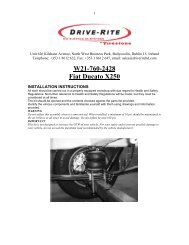
<strong>W21</strong>-<strong>760</strong>-<strong>2110</strong><br />
<strong>Fiat</strong> <strong>Ducato</strong>, <strong>Citreon</strong> <strong>Jumper</strong>, <strong>Peugoet</strong> Boxer,<br />
Talbot Express. Euro Chassis X230<br />
INSTALLATION INSTRUCTIONS<br />
All work should be carried out in a properly equipped workshop with due regard to Health and Safety<br />
Regulations. No further reference to Health and Safety Regulations will be made, but they must be<br />
considered at all times.<br />
The kit should be opened and the contents checked against the parts list provided.<br />
Identify the various components and familiarise yourself with them using drawings and information<br />
provided.<br />
WARNING<br />
Do not inflate this assembly when it is unrestricted. When installed, a minimum of 10 psi should be maintained in<br />
the air bellows at all times to avoid damage. Do not inflate beyond 100 psi.<br />
IMPORTANT<br />
This kit is not designed to increase the GVW of your vehicle. For your safety and to prevent possible damage to<br />
your vehicle, do not exceed the maximum load recommended by the vehicle manufacturer.
2<br />
Parts List<br />
Description Quantity Description Quantity<br />
255C1.5” AIR BELLOWS 2 3/8” - 16 X 8” CARRIAGE BOLT 8<br />
UPPER BRACKET 2 3/8” - 16 UNC FLANGE LOCK NUT 12<br />
INNER BRACKET 2 3/8” - 16 UNC X 3/4” BOLT 2<br />
LOWER BRACKET 2 1/4” ELBOW 2<br />
BRACKET STRAP 4 1/4” TEE PIECE 1<br />
5/16” - 18 X 3.5” HEX BOLT 4 1/4” INFLATION VALVE 2<br />
5/16” - 18 HEX NUT 4 NYLON TIES 15<br />
5/16” LOCK WASHER 4 THERMAL SLEEVE 2<br />
5/16” FLAT WASHER 4 1/4” TUBING 18 FT 1<br />
M10 LOCK WASHER 2 3/8” X 4” POLY TUBE 2<br />
M10 X 1.25 X 30 MM HEX HEAD BOLT 2 Poly Loom 2<br />
INSTALLATION:<br />
STEP 1: PREPARE THE VEHICLE<br />
Your vehicle is equipped with a rubber bump stop which is positioned on the frame directly<br />
above the axle. Remove this bump stop together with bracket and discard. Bolt the top inner<br />
bracket (A) to the chassis rail using the M10 bolt and lock washer (1). Ensure that the slot<br />
cut out of the top inner bracket is facing towards the centre of the vehicle as shown in<br />
diagram.<br />
STEP 2: MOUNT LOWER BRACKET TO BELLOWS<br />
Fasten the bellows to the lower bracket (C), as shown in diagram, using<br />
3/8” hex bolt and spring washers (4) provided.<br />
STEP 3: INSTALL THE AIR FITTING<br />
Install the elbow in the air inlet hole on the top plate of the bellows. Tighten until the elbow<br />
is pointing towards the centre of the vehicle. Next, cut the air line into two equal lengths,<br />
making the cut as square to the axis of the tubing as possible. Insert the air line into the<br />
elbow and push until a positive click is felt.<br />
STEP 4: MOUNT UPPER BRACKET TO BELLOWS<br />
The top of the bellows has two studs and an air inlet hole. Position the top outer bracket (B)<br />
on the bellows ensuring that the elbow is exposed in the slot cut out of the bracket. Fasten<br />
the bracket to the bellows using 3/8” hex nuts and spring washers.<br />
STEP 5: INSTALL THE ASSEMBLY<br />
Place the assembly on the springs and position so that the lower bracket rests on the spring<br />
pack as shown in diagram. Bolt the top outer bracket (B) to the inner bracket (A) using the<br />
5/16” nuts and bolts (2). Position the lower bracket so that it is level on the spring pack and<br />
bolt in place using the 3/8” carriage bolts (5) and channel straps (6) provided.<br />
STEP 6: INSTALL THE AIR LINE<br />
Select locations on the vehicle for the air inflation valves. The locations can be on the<br />
bumper or on the body of the vehicle. Drill a 5/16” hole and install the air inflation valve.<br />
Run the tubing from the bellows to the valve, routing it so that it will be protected from the<br />
direct heat of the exhaust system, and away from sharp edges. Secure the tubing in place<br />
with nylon ties. Attach the end of the air line tubing to the inflation valve.<br />
Once the inflation valves are installed, inflate the bellows to the recommended pressure and<br />
check the fittings for air leaks. If a leak is detected at a tubing connection then check to<br />
make sure that the tube is cut as square as possible and that it is pushed completely into the<br />
fitting. If a leak is detected where the brass elbow fitting screws into the spring, then screw<br />
the elbow into the spring one additional turn until the leak stops.