Structural Analysis of an Articulated Urban Bus Chassis via FEM: a ...
Structural Analysis of an Articulated Urban Bus Chassis via FEM: a ...
Structural Analysis of an Articulated Urban Bus Chassis via FEM: a ...

You also want an ePaper? Increase the reach of your titles
YUMPU automatically turns print PDFs into web optimized ePapers that Google loves.
Strojniški vestnik - Journal <strong>of</strong> Mech<strong>an</strong>ical Engineering 57(2011)11, 799-809 Paper received: 05.04.2011<br />
DOI:10.5545/sv-jme.2011.077 Paper accepted: 04.10.2011<br />
<strong>Structural</strong> <strong>Analysis</strong> <strong>of</strong> <strong>an</strong> <strong>Articulated</strong> Urb<strong>an</strong> <strong>Bus</strong> <strong>Chassis</strong> <strong>via</strong><br />
<strong>FEM</strong>: a Methodology Applied to a Case Study<br />
Croccolo, D. ‒ De Agostinis, M. ‒ Vincenzi, N.<br />
Dario Croccolo * ‒ Massimili<strong>an</strong>o De Agostinis ‒ Nicolò Vincenzi<br />
DIEM, Department <strong>of</strong> Mech<strong>an</strong>ical Engineering, University <strong>of</strong> Bologna, Italy<br />
This paper deals with the static structural <strong>an</strong>alysis <strong>of</strong> <strong>an</strong> articulated urb<strong>an</strong> bus chassis, carried<br />
out with the Finite Elements Method. The purpose <strong>of</strong> this work is to simulate <strong>an</strong>d forecast the structural<br />
response <strong>of</strong> the chassis, in terms <strong>of</strong> stress, strain <strong>an</strong>d displacement, under several loading <strong>an</strong>d constraining<br />
conditions, which aim at reflecting the actual duty cycle <strong>of</strong> the bus. A thorough interaction with the customer<br />
comp<strong>an</strong>y allowed the authors to adequately define the loading scheme <strong>an</strong>d to constrain the structure<br />
properly. Sensitivity <strong>an</strong>alyses about <strong>FEM</strong> parameters have been run, in order to achieve <strong>an</strong> adequate<br />
trade <strong>of</strong>f between computational time <strong>an</strong>d results accuracy. Obtained results have been double checked by<br />
employing both solid (3D) <strong>an</strong>d shell (2D) elements for each simulation. Eventually, the customer has been<br />
notified <strong>of</strong> critical issues <strong>an</strong>d the related suggested improvements.<br />
©2011 Journal <strong>of</strong> Mech<strong>an</strong>ical Engineering. All rights reserved.<br />
Keywords: bus, structure, frame, chassis, case study<br />
0 INTRODUCTION<br />
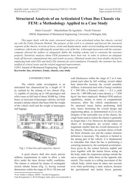
The vehicle under investigation is <strong>an</strong><br />
articulated bus characterized by a length <strong>of</strong> 18<br />
m, realised by the joining <strong>of</strong> two chassis (Fig.<br />
1), capable <strong>of</strong> carrying up to 160 passengers <strong>an</strong>d<br />
with a mass at full load <strong>of</strong> about 30,000 kg. Urb<strong>an</strong><br />
buses, as most part <strong>of</strong> passenger vehicles, are built<br />
around a tubular chassis that bears both the weight<br />
<strong>of</strong> the vehicle itself <strong>an</strong>d the weight <strong>of</strong> passengers<br />
<strong>an</strong>d luggage.<br />
Fig.1. Urb<strong>an</strong> bus <strong>an</strong>d respective chassis<br />
A good chassis shall also meets precise<br />
stiffness requirements in order to allow a safe<br />
drive under the most diverse traffic conditions.<br />
The chassis is realized by me<strong>an</strong>s <strong>of</strong> rect<strong>an</strong>gular<br />
section tubular beams (Fig. 1), having external<br />
dimensions within the r<strong>an</strong>ge <strong>of</strong> 30 to 150 mm <strong>an</strong>d<br />
wall thicknesses within the r<strong>an</strong>ge <strong>of</strong> 2 to 8 mm,<br />
joined each other by full welding; several added<br />
bent sheets-ribs increase the overall assembly<br />
stiffness. A structural steel with a Young’s modulus<br />
E = 200 GPa, a Poisson’s ratio ν = 0.3, a yield<br />
stress Sy = 400 MPa <strong>an</strong>d a mass density ρ = 7,850<br />
kg/m 3 has been employed. Modern <strong>FEM</strong> <strong>an</strong>alysis<br />
capabilities, mainly in terms <strong>of</strong> computational<br />
resources, allow the vehicle m<strong>an</strong>ufacturer to<br />
fix structural issues before performing field<br />
tests, hence shortening the overall design <strong>an</strong>d<br />
engineering phase, as demonstrated in [1] to [4].<br />
Despites <strong>of</strong> the noticeable size <strong>of</strong> the chassis, the<br />
single beam used to realize the chassis is generally<br />
no longer th<strong>an</strong> 1.5 m. Moreover, the displacements<br />
object <strong>of</strong> investigation are several orders <strong>of</strong><br />
magnitude smaller th<strong>an</strong> the overall dimensions <strong>of</strong><br />
the chassis. Therefore, <strong>an</strong> accurate choice <strong>of</strong> both<br />
the finite elements size <strong>an</strong>d the contact elements<br />
definition is necessary. The <strong>an</strong>alysis is limited to<br />
the sprung part <strong>of</strong> the vehicle: it is fundamental<br />
to remember that when the bus is performing a<br />
cornering m<strong>an</strong>oeuvre, the centripetal accelerationforce<br />
given by the contact between asphalt <strong>an</strong>d<br />
tyres together with the inertia forces acting on<br />
the body, make the suspension springs outside the<br />
curve compress, while those on the opposite side<br />
stretch. This results in a rolling movement <strong>of</strong> the<br />
vehicle body, which must be taken into account<br />
even when performing a static <strong>an</strong>alysis, because<br />
the gravitational <strong>an</strong>d inertia forces generate<br />
*Corr. Author’s Address: DIEM - Facoltà di Ingegneria,<br />
Viale Risorgimento 2, 40136 Bologna, Italia, dario.croccolo@unibo.it<br />
799
Strojniški vestnik - Journal <strong>of</strong> Mech<strong>an</strong>ical Engineering 57(2011)11, 799-809<br />
different stress/strain distributions within the<br />
structure depending on its position with respect<br />
to a system <strong>of</strong> coordinates which is fixed to the<br />
ground, as suggested in [5]. Such behaviour could<br />
be well simulated by a bus model, which included<br />
the whole suspensions group [6].<br />
1 PRELIMINARY REMARKS<br />
The top level assembly <strong>of</strong> the chassis<br />
consists <strong>of</strong> about 1,500 parts, which belong to<br />
sub–structures representing, for inst<strong>an</strong>ce, the floor,<br />
the ro<strong>of</strong> <strong>an</strong>d the body sides <strong>of</strong> the chassis. Due to<br />
hardware limitations, it would be impossible to<br />
<strong>an</strong>alyze the whole structure (Fig. 1) at one time,<br />
hence the overall assembly has been divided<br />
into two sub assemblies, one being the front half<br />
<strong>of</strong> the chassis <strong>an</strong>d one the rear part <strong>of</strong> it: from<br />
now on, they will be respectively referred to as<br />
A-chassis <strong>an</strong>d B-chassis. Such a large structures<br />
would be generally <strong>an</strong>alyzed by introducing<br />
rough approximations mainly concerning the<br />
loading <strong>an</strong>d constraining hypotheses (uniform<br />
loads distributions [7]) or by me<strong>an</strong>s <strong>of</strong> beam (1D)<br />
elements [8].<br />
The A-chassis, whose two front wheels<br />
are steering while the rear ones are fixed,<br />
comprehends the pilot’s station: two passengers<br />
doors open on the right side <strong>of</strong> this chassis. A half<br />
part <strong>of</strong> the articulation system (the device that<br />
joins the two halves <strong>of</strong> the bus allowing them to<br />
rotate respectively around the vertical axis), is<br />
installed by the rear side <strong>of</strong> the A-chassis.<br />
The B-chassis has only two wheels on<br />
the rear <strong>an</strong>d h<strong>an</strong>gs on the A-chassis by me<strong>an</strong>s<br />
<strong>of</strong> the other part <strong>of</strong> the articulation system. This<br />
chassis has no steering devices but it carries the<br />
engine group on the rear left side: two passengers<br />
doors are on the right side. Each chassis has<br />
been <strong>an</strong>alyzed under six different loading <strong>an</strong>d<br />
constraining schemes (cases), which aimed<br />
at simulating the chassis behaviour under the<br />
following conditions:<br />
(a) the action <strong>of</strong> gravitational acceleration;<br />
(b) the braking at the upper deceleration limit <strong>of</strong><br />
the vehicle;<br />
(c) the both sides cornering m<strong>an</strong>oeuvres at the<br />
capsizing limit;<br />
(d) the both sides torsion due to uneven road<br />
surface.<br />
A Cartesi<strong>an</strong> Coordinate System has<br />
been chosen [5] with its origin into centre <strong>of</strong><br />
the articulation system: X-axis is oriented as<br />
the driving gear, Z-axis is pointing upwards <strong>an</strong>d<br />
Y-axis follows the right h<strong>an</strong>d rule.<br />
2 FEA SETUP<br />
The main structural elements <strong>of</strong> steel<br />
framed structures (e.g. the bus chassis, Fig.<br />
1) have to be studied as the assembly <strong>of</strong> three<br />
different components, namely, columns, beam <strong>an</strong>d<br />
their joints (Fig. 2).<br />
Fig. 2. Example <strong>of</strong> steel framed structure: main<br />
structural components (column, beam <strong>an</strong>d joint)<br />
The capacity <strong>of</strong> steel frames to resist<br />
loads is determined more by the strength <strong>an</strong>d,<br />
in particular, the stiffness <strong>of</strong> the joints th<strong>an</strong> by<br />
the properties <strong>of</strong> the members themselves [9]. In<br />
practice, beam-to-column joints in conventional<br />
<strong>an</strong>alysis <strong>an</strong>d design <strong>of</strong> steel frameworks are usually<br />
assumed to behave either ideally pinned or fully<br />
rigid. Conversely, experimental investigations<br />
[10] show that the true behaviour <strong>of</strong> joints lies in<br />
between that <strong>of</strong> ideally compli<strong>an</strong>t <strong>an</strong>d fully rigid:<br />
such joints are referred to as semi-rigid joints.<br />
Overestimating the joint stiffness may result in<br />
underestimating the forces developed in beam <strong>an</strong>d<br />
column <strong>an</strong>d the overall displacement <strong>of</strong> the global<br />
frame structure. Neglecting the real behaviour <strong>of</strong><br />
the joint may lead to unrealistic predictions <strong>of</strong><br />
the response <strong>an</strong>d reliability <strong>of</strong> steel frames [11]:<br />
both <strong>of</strong> these extreme assumptions are inaccurate<br />
<strong>an</strong>d uneconomic. When approaching the problem<br />
by a numerical (<strong>FEM</strong>) st<strong>an</strong>dpoint the latter issues<br />
occur in formulating the contact parameters<br />
between two or more structural members. When<br />
dealing with contacts there is a lot more to control<br />
800 Croccolo, D. ‒ De Agostinis, M. ‒ Vincenzi, N.
Strojniški vestnik - Journal <strong>of</strong> Mech<strong>an</strong>ical Engineering 57(2011)11, 799-809<br />
th<strong>an</strong> the mesh size type [12] <strong>an</strong>d in particular the<br />
contact formulation as well as the contact stiffness<br />
parameters. Finite Elements Analyses have<br />
been performed by me<strong>an</strong>s <strong>of</strong> the Ansys Code,<br />
Workbench Release 12. In order to m<strong>an</strong>age the<br />
contact formulation, the Augmented Lagr<strong>an</strong>gi<strong>an</strong><br />
Method has been chosen as it allows, by m<strong>an</strong>ually<br />
setting the contact stiffness parameters, a better<br />
approximation <strong>of</strong> the interactions occurring within<br />
the contact areas <strong>of</strong> welded structures. As a matter<br />
<strong>of</strong> fact the Augmented Lagr<strong>an</strong>gi<strong>an</strong> is <strong>an</strong> iterative<br />
method working by two consequent steps: firstly,<br />
like a simple Penalty Method, locally modifying<br />
the bodies’ normal stiffness in the contact region<br />
until the equilibrium is satisfied. Then, if <strong>an</strong>y<br />
interference (penetration) occurred, it proceeds<br />
adding a convenient pressure to the mating<br />
surfaces, until the interference is overridden. The<br />
contact stiffness parameter (normal or t<strong>an</strong>gential)<br />
c<strong>an</strong> be input as <strong>an</strong> absolute value (KN or KT) or as<br />
a factor (FKN or FKT) to the default Hertz contact<br />
stiffness KH, which depends on the component<br />
geometry <strong>an</strong>d material. For surface-to-surface<br />
contact elements, Ref. [13] recommends a FKN<br />
value in the r<strong>an</strong>ge from 0.001 to 100 (default<br />
value 1.0): ch<strong>an</strong>ges in such r<strong>an</strong>ge strongly affect<br />
the solution in terms <strong>of</strong> stresses, strains <strong>an</strong>d<br />
displacements. FKN value shall be tuned by<br />
me<strong>an</strong>s <strong>of</strong> experimental <strong>an</strong>alyses. Experimental<br />
results on a full welded T-joint, comparable in<br />
dimensions <strong>an</strong>d welding method to that used on<br />
the bus chassis (Fig. 3), have been obtained by<br />
Y<strong>an</strong>g <strong>an</strong>d Kim [10].<br />
<strong>of</strong> 12 mm occurs at the same point. Numerical<br />
results in terms <strong>of</strong> upper beam displacements as<br />
a function <strong>of</strong> the FKN parameter are reported in<br />
Table 1 <strong>an</strong>d shown in Fig. 4: a FKN value between<br />
0.01 <strong>an</strong>d 0.005 <strong>of</strong>fers a reliable prediction <strong>of</strong><br />
experimental results.<br />
Table 1. FEA displacements as a function <strong>of</strong> the<br />
FKN parameter<br />
Experimental displacement ≈ 12 mm [9]<br />
FKN - Normal Stiffness<br />
Factor<br />
FEA displacement<br />
[mm]<br />
Default (1.0) 8.13<br />
0.1 8.51<br />
0.05 8.80<br />
0.01 10.68<br />
0.005 12.70<br />
0.001 26.82<br />
Fig. 3. Full welded T-joint specimen tested in [9]<br />
In particular, they established that under<br />
the maximum force (for the linear elastic field)<br />
<strong>of</strong> 42.1 kN applied to the upper hinge a deflection<br />
Fig. 4. Deformed shape (14× magnification) <strong>of</strong><br />
the T-joint specimen tested in [9] as a function <strong>of</strong><br />
the contact normal stiffness factor FKN in Table 1<br />
The evaluation <strong>of</strong> the tensile state in the<br />
vicinity <strong>of</strong> the weld toe (e.g. hot spot stress method<br />
<strong>Structural</strong> <strong>Analysis</strong> <strong>of</strong> <strong>an</strong> <strong>Articulated</strong> Urb<strong>an</strong> <strong>Bus</strong> <strong>Chassis</strong> <strong>via</strong> <strong>FEM</strong>: a Methodology Applied to a Case Study<br />
801
Strojniški vestnik - Journal <strong>of</strong> Mech<strong>an</strong>ical Engineering 57(2011)11, 799-809<br />
or the peak stress method recently proposed by<br />
Meneghetti et al. [14]) is not the object <strong>of</strong> this<br />
work. No welds are, accordingly, modelled in the<br />
chassis geometry; the connection between beam<br />
<strong>an</strong>d column is m<strong>an</strong>aged by the contact stiffness<br />
parameters, as shown in [8]. In order to check the<br />
numerical structural stress state <strong>of</strong> the beam <strong>an</strong>d<br />
column (far from the weld toe), a comparison with<br />
the data evaluated <strong>via</strong> strain gages in a square-tosquare<br />
hollow section T-joint [14] <strong>an</strong>d [15], has<br />
been performed. Both solid (3D) mesh <strong>an</strong>d shell<br />
(2D) mesh have been compared to the results<br />
obtained in the reference geometry reported in<br />
Fig. 5 [14] <strong>an</strong>d [15].<br />
The applied loads are reported in Fig. 5,<br />
while the stress results (in terms <strong>of</strong> maximum<br />
principal stress as suggested by the peak stress<br />
method [14]) in Fig. 6. An attentive examination<br />
<strong>of</strong> the results shows that at a dist<strong>an</strong>ce almost equal<br />
to the cross section dimensions (dashed lines) the<br />
stresses evaluated both <strong>via</strong> 3D mesh <strong>an</strong>d <strong>via</strong> 2D<br />
mesh (without modeling the weld) converged to<br />
the reference one [14] <strong>an</strong>d [15].<br />
As suggested in [16], tubular joints have<br />
been meshed by using shell (2D) elements that<br />
represent the mid-surfaces <strong>of</strong> the joint member<br />
walls. As shown previously <strong>an</strong>d as accurately<br />
demonstrated in [17], the results are perfectly<br />
comparable with the ones obtained by me<strong>an</strong>s <strong>of</strong> a<br />
solid (3D) mesh: the second technique is still ten<br />
times more dem<strong>an</strong>ding th<strong>an</strong> the first in terms <strong>of</strong><br />
disk space.<br />
3 FEA LOADING CASES<br />
Each load applied to the A-chassis as<br />
well as to the B-chassis has been introduced as a<br />
lumped mass. These masses undergo acceleration<br />
components imposed by the conditions described<br />
in Section 1, <strong>an</strong>d are attached to one or more<br />
surfaces belonging to one or more chassis<br />
components. Using lumped masses rather th<strong>an</strong><br />
remote forces results in a speed up <strong>of</strong> the workflow<br />
when the boundary conditions have to be ch<strong>an</strong>ged.<br />
For example, the gravitational acceleration c<strong>an</strong><br />
Fig. 5. The square-to-square hollow section T-joint specimen tested in [13] <strong>an</strong>d [14]<br />
a) b) c)<br />
Fig. 6. Comparison in stress distributions (deformed shape 50x magnification) far from the joint between<br />
beam <strong>an</strong>d column (dashed lines); a) reference geometry [13] <strong>an</strong>d [14] with the welded joint modelled, b)<br />
solid mesh without the weld, c) shell mesh without the weld; mesh size: 1 mm<br />
802 Croccolo, D. ‒ De Agostinis, M. ‒ Vincenzi, N.
Strojniški vestnik - Journal <strong>of</strong> Mech<strong>an</strong>ical Engineering 57(2011)11, 799-809<br />
be quickly ch<strong>an</strong>ged into the forward or lateral<br />
accelerations acting on the system.<br />
For remote boundaries conditions, such<br />
as the lumped masses defined, Ansys allows the<br />
control <strong>of</strong> the specific geometry behaviour, which<br />
c<strong>an</strong> be defined as either rigid or deformable. A<br />
deformable behaviour has been chosen here by<br />
the authors, as it represents the actual response<br />
<strong>of</strong> the structure well: in fact, on the other h<strong>an</strong>d,<br />
the masses application areas would result in being<br />
unreasonably undeformable.<br />
Since the B-chassis is attached to the<br />
A-chassis by me<strong>an</strong>s <strong>of</strong> <strong>an</strong> articulation device, the<br />
<strong>an</strong>alyses on the B-chassis were carried out first,<br />
assuming the constraints between the B-chassis<br />
<strong>an</strong>d the A-chassis to be <strong>of</strong> the hinge type, <strong>an</strong>d to<br />
be applied on the edges <strong>of</strong> the articulation device.<br />
Accordingly, when performing the corresponding<br />
<strong>an</strong>alysis the reaction forces <strong>of</strong> the same magnitude<br />
evaluated on the articulation device were applied,<br />
but opposite in direction to the A-chassis.<br />
The results in terms <strong>of</strong> total displacement<br />
<strong>an</strong>d Von Mises equivalent stress distribution have<br />
been computed <strong>an</strong>d <strong>an</strong>alyzed for each condition.<br />
Constraint reactions in magnitude <strong>an</strong>d<br />
direction have been checked to be equal to the<br />
imposed loads in magnitude <strong>an</strong>d direction as <strong>an</strong><br />
overall verification <strong>of</strong> the simulation process.<br />
line formed by a single edge, c<strong>an</strong> be considered<br />
equivalent to <strong>an</strong> ideal hinge that locks rotational<br />
motions around X-axis <strong>an</strong>d Z-axis <strong>an</strong>d tr<strong>an</strong>slation<br />
along each axis. Then, the st<strong>an</strong>dard gravitational<br />
acceleration g (9.81 m/s 2 ) has been applied to the<br />
whole mass system.<br />
Fig. 7. B-chassis: example <strong>of</strong> distributed masses<br />
related to the main body structure<br />
3.1 B-<strong>Chassis</strong><br />
At first, lumped masses (represented as<br />
spheres) have been applied to the chassis. In Fig.<br />
7, for inst<strong>an</strong>ce, 2,950 kg <strong>of</strong> distributed masses<br />
belonging to coatings <strong>an</strong>d body p<strong>an</strong>els are shown:<br />
each sphere has the same color <strong>of</strong> its target parts.<br />
Masses related to onboard systems, windows<br />
<strong>an</strong>d doors (1,046 kg) <strong>an</strong>d those belonging to<br />
passengers’ mass (4,931 kg) have been, instead,<br />
represented in Fig. 8. The 1,500 kg engine mass<br />
has been subdivided into three lumped masses:<br />
each <strong>of</strong> them has been applied to the relev<strong>an</strong>t<br />
engine mount on the chassis. The B-chassis self<br />
weight is 1,658 kg.<br />
3.1.1 B-<strong>Chassis</strong>, Gravitational Acceleration<br />
Fixed supports have been applied both to<br />
the rear axle edges <strong>an</strong>d to the articulation device<br />
edges: this type <strong>of</strong> constraints, since applied to a<br />
Fig. 8. B-chassis loads <strong>an</strong>d constraints – loading<br />
case 3.1.2<br />
3.1.2 B-<strong>Chassis</strong>, Gravitational Acceleration <strong>an</strong>d<br />
Braking Deceleration<br />
In order to simulate the effects <strong>of</strong> a severe<br />
brake, a 0.75·g acceleration [5] <strong>an</strong>d [18] has<br />
been added along the positive X direction. The<br />
gravitational acceleration still acts on the system.<br />
Moreover, the rear axle edges constraints have<br />
been redefined according to Fig. 8, allowing them<br />
to tr<strong>an</strong>slate only along X-axis (Z-axis <strong>an</strong>d Y-axis<br />
displacements are still equal to zero). At the same<br />
time, braking forces F μ (Eq. (1)) have been applied<br />
to the lower edges <strong>of</strong> the rear axle (see Fig. 8, flag<br />
D <strong>an</strong>d E), by imposing the Coulomb friction law<br />
[18] to [20]:<br />
<strong>Structural</strong> <strong>Analysis</strong> <strong>of</strong> <strong>an</strong> <strong>Articulated</strong> Urb<strong>an</strong> <strong>Bus</strong> <strong>Chassis</strong> <strong>via</strong> <strong>FEM</strong>: a Methodology Applied to a Case Study<br />
803
Strojniški vestnik - Journal <strong>of</strong> Mech<strong>an</strong>ical Engineering 57(2011)11, 799-809<br />
F μ = μ·F Zr,B . (1)<br />
This hypothesis considers the rear wheels<br />
subjected to the braking force F μ , while the front<br />
articulation edges hold up the remaining X-axis<br />
force R x given by Eq. (2) (Fig. 8a):<br />
R x = m B-chassis·0.75·g ‒ F μ . (2)<br />
Such a constraint scheme produces the<br />
highest stresses <strong>an</strong>d displacements on the structure<br />
because the whole B-chassis is subjected to both<br />
the bending moment <strong>an</strong>d the compression force<br />
generated by the inertial loads. Conversely, in<br />
the two remaining schemes (Figs. 8b <strong>an</strong>d c) loads<br />
<strong>an</strong>d moments are partially supported by the rear<br />
constraint <strong>an</strong>d, therefore, they are not affecting the<br />
central section <strong>of</strong> the frame.<br />
Since F Zr,B ch<strong>an</strong>ges during the brake<br />
depending on the load tr<strong>an</strong>sfer from the rear axle<br />
to the front support [21] <strong>an</strong>d [22], the correct<br />
F Zr,B value has been determined by some iterative<br />
<strong>an</strong>alyses: firstly, the vertical constraint reaction<br />
on the rear axle are determined from the static<br />
equilibrium (F Zr,B_1 ) <strong>an</strong>d the simulation has been<br />
run using F μ = μ·F Zr,B_1 , then the actual vertical<br />
constraint reactions on the rear axle (F Zr,B_2 ) has<br />
been calculated. A new simulation has been run<br />
again assuming F μ = μ·F Zr,B_2 <strong>an</strong>d calculating the<br />
actual vertical constraint reactions on the rear<br />
axle (F Zr,B_3 ). The same procedure <strong>of</strong> assuming<br />
F μ = μ·F Zr,B_i <strong>an</strong>d calculating the actual vertical<br />
constraint reactions (F Zr,B_i+1 ) lasted until no<br />
signific<strong>an</strong>t discrep<strong>an</strong>cy has been found between<br />
two subsequent values <strong>of</strong> F Zr,B (F Zr,B_i ≈ F Zr,B_i+1 ).<br />
3.1.3 B-<strong>Chassis</strong>, Gravitational Acceleration <strong>an</strong>d<br />
Cornering<br />
Since the chassis is not symmetric about<br />
XZ-pl<strong>an</strong>e (see Fig. 7), two simulations have been<br />
run in order to evaluate the effects <strong>of</strong> both right<br />
<strong>an</strong>d left cornering m<strong>an</strong>oeuvres performed on a<br />
plain ground. Since the st<strong>an</strong>dard gravitational<br />
acceleration is always present, <strong>an</strong> acceleration<br />
vector having a magnitude <strong>of</strong> 0.75·g <strong>an</strong>d directed<br />
along Y-axis, (positive or negative depending<br />
on the turning direction) has been added to the<br />
system. The constraints remain the same used for<br />
the brake simulation. It is import<strong>an</strong>t to verify that<br />
the rear axle reactions provided by the <strong>an</strong>alysis<br />
exclude <strong>an</strong>y capsizing tendency <strong>of</strong> the vehicle<br />
when subjected to this loading case: both <strong>of</strong> the<br />
rear constraints must have positive reactions along<br />
Z-axis.<br />
3.1.4 B-<strong>Chassis</strong>, Torsion<br />
The chassis could be subjected to torsion<br />
when, for example, the bus should run on <strong>an</strong><br />
uneven asphalt mat. In order to recreate such a<br />
condition, two <strong>an</strong>alyses have been performed,<br />
suppressing two <strong>of</strong> the total four constraints at a<br />
time <strong>an</strong>d applying the sole st<strong>an</strong>dard gravitational<br />
acceleration. The supports to be suppressed<br />
have been chosen as follows: (i) left articulation<br />
constraint <strong>an</strong>d right rear axle constraint; (ii) right<br />
articulation constraint <strong>an</strong>d left rear axle constraint.<br />
In this way, the chassis could twist around<br />
the axis that joints the remaining supports.<br />
3.2 A-<strong>Chassis</strong><br />
Lumped masses were applied to this chassis<br />
<strong>an</strong>d for the B-chassis: 2901 kg <strong>of</strong> distributed<br />
masses belonging to coatings <strong>an</strong>d body p<strong>an</strong>els,<br />
494 kg related to windows <strong>an</strong>d doors, 5822 kg<br />
belonging to passengers <strong>an</strong>d the driver <strong>an</strong>d 1540<br />
kg related to relev<strong>an</strong>t systems have beenw applied<br />
to the chassis. The A-chassis self weight is 2252<br />
kg.<br />
Fig. 9. A-chassis loads <strong>an</strong>d constraints – loading<br />
case 3.2.1<br />
Fig. 10. A-chassis loads <strong>an</strong>d constraints – loading<br />
case 3.2.2<br />
As mentioned before, the reactions on the<br />
articulation device edges have beencarried over<br />
804 Croccolo, D. ‒ De Agostinis, M. ‒ Vincenzi, N.
Strojniški vestnik - Journal <strong>of</strong> Mech<strong>an</strong>ical Engineering 57(2011)11, 799-809<br />
from the <strong>an</strong>alyses performed on the B-chassis<br />
(opposite in direction), as shown in Figs. 9 <strong>an</strong>d 10.<br />
3.2.1 A-<strong>Chassis</strong>, Gravitational Acceleration<br />
Fixed supports have been applied both to<br />
the rear <strong>an</strong>d to the front axle edges: this type <strong>of</strong><br />
constraints is equivalent to <strong>an</strong> ideal hinge locking<br />
rotational motions around X-axis <strong>an</strong>d Z-axis<br />
<strong>an</strong>d tr<strong>an</strong>slation along each axis. The st<strong>an</strong>dard<br />
gravitational acceleration g (9.81 m/s 2 ) has been<br />
applied to the system.<br />
3.2.2 A-<strong>Chassis</strong>, Gravitational Acceleration <strong>an</strong>d<br />
Braking Deceleration<br />
In order to simulate the effects <strong>of</strong> a severe<br />
brake, a 0.75·g acceleration has been added<br />
along the positive X direction. The gravitational<br />
acceleration still acts on the system. Moreover,<br />
braking forces have been applied to the lower<br />
edges <strong>of</strong> the rear axle, which have been allowed to<br />
tr<strong>an</strong>slate along X-axis, while the front axle edges<br />
have been locked towards the three components <strong>of</strong><br />
tr<strong>an</strong>slation. As for the B-chassis, such constraining<br />
hypotheses make the chassis working under the<br />
worst condition <strong>of</strong> free deflection length. Braking<br />
forces intensity defined by iteration, as was<br />
formerly done for the B-chassis.<br />
3.2.3 A-<strong>Chassis</strong>, Gravitational Acceleration <strong>an</strong>d<br />
Cornering<br />
Since the chassis is not symmetric about<br />
XZ-pl<strong>an</strong>e (the passenger doors are located on<br />
the right side), two simulations have been run<br />
in order to evaluate the effects <strong>of</strong> both right <strong>an</strong>d<br />
left cornering m<strong>an</strong>oeuvres performed on a plain<br />
ground. The st<strong>an</strong>dard gravitational acceleration<br />
still acts on the system, together with <strong>an</strong><br />
acceleration vector directed along Y-axis with a<br />
0.75·g magnitude (positive or negative depending<br />
on the turning direction).<br />
The constraints are still the same used<br />
for the brake simulation. The rear axle reactions<br />
provided by the <strong>an</strong>alysis exclude <strong>an</strong>y capsizing<br />
tendency <strong>of</strong> the vehicle when subjected to this<br />
loading case: in fact both <strong>of</strong> the rear constraints<br />
have positive reactions along Z-axis.<br />
3.2.4 A-<strong>Chassis</strong>, Torsion<br />
Two torsion <strong>an</strong>alyses have been performed<br />
also on the A-chassis by suppressing two <strong>of</strong> the<br />
four supports at a time <strong>an</strong>d applying the st<strong>an</strong>dard<br />
gravitational acceleration. The supports to be<br />
suppressed have been chosen as follows:<br />
(i) Left front axle constraint <strong>an</strong>d right rear axle<br />
constraint;<br />
(ii) Right front axle constraint <strong>an</strong>d left rear axle<br />
constraint.<br />
In this way, the chassis c<strong>an</strong> twist around<br />
the axis that joints the remaining supports.<br />
4 FEA RESULTS AND DISCUSSION<br />
The sum <strong>of</strong> the external loads applied<br />
to the structure <strong>an</strong>d the sum <strong>of</strong> the constraints<br />
reactions have been compared for each <strong>an</strong>alysis<br />
in order to evaluate the overall equilibrium <strong>of</strong><br />
the chassis <strong>an</strong>d, therefore, exclude macroscopic<br />
errors affecting the results. The resume <strong>of</strong> such<br />
verification is reported in the Appendix at the<br />
end <strong>of</strong> the m<strong>an</strong>uscript: the results are subdivided<br />
into four kinds <strong>of</strong> loading cases (vertical, braking,<br />
cornering, torsion) respectively, for the A-chassis<br />
<strong>an</strong>d B-chassis in terms <strong>of</strong> constraints or external<br />
loads direction <strong>an</strong>d magnitude. As shown in the<br />
Appendix, discrep<strong>an</strong>cies are always lower th<strong>an</strong><br />
0.3%. A stress limit equal to S l = 150 MPa (safety<br />
factor <strong>of</strong> 2.6 with respect to the yield limit), has<br />
been chosen in accord<strong>an</strong>ce with the customer: the<br />
multiaxial stress states have been compared with<br />
the uniaxial material properties by me<strong>an</strong>s <strong>of</strong> the<br />
Von-Mises yield criterion. Even if static <strong>an</strong>alyses<br />
have been performed, Meznar <strong>an</strong>d Lazovic<br />
[23], L<strong>an</strong> et al. [24] <strong>an</strong>d Kim et al. [25] have<br />
demonstrated the import<strong>an</strong>ce <strong>of</strong> these preliminary<br />
FEA results for further experimental <strong>an</strong>alyses<br />
(e.g. strain gauges as deep demonstrated in [23])<br />
performed on typical duty cycles.<br />
4.1 A-<strong>Chassis</strong><br />
The A-chassis has a good overall response<br />
to every imposed loading condition, since no<br />
signific<strong>an</strong>t area <strong>of</strong> it exceeded the established<br />
equivalent stress limit S l . Braking <strong>an</strong>d cornering<br />
conditions, according to [23], are the most severe<br />
because stresses show up close to S l , interesting<br />
<strong>Structural</strong> <strong>Analysis</strong> <strong>of</strong> <strong>an</strong> <strong>Articulated</strong> Urb<strong>an</strong> <strong>Bus</strong> <strong>Chassis</strong> <strong>via</strong> <strong>FEM</strong>: a Methodology Applied to a Case Study<br />
805
Strojniški vestnik - Journal <strong>of</strong> Mech<strong>an</strong>ical Engineering 57(2011)11, 799-809<br />
a) b)<br />
Fig. 11. Stress distributions in A (a) <strong>an</strong>d B (b) chassis in most severe (cornering) loading condition<br />
different areas depending on the loading case.<br />
Some chassis portions underneath the floor <strong>an</strong>d<br />
close to the articulation device are impacted by<br />
the effects <strong>of</strong> braking with Von-Mises stress me<strong>an</strong><br />
values <strong>of</strong> about 100 MPa (Fig. 11a), essentially<br />
due to forces tr<strong>an</strong>smitted by the B-chassis <strong>via</strong> the<br />
articulation device itself. The right side pillars <strong>an</strong>d<br />
the J-shaped tubular beams, which connect the<br />
ro<strong>of</strong> to the right body side, have stress values <strong>of</strong><br />
about 130 MPa when the left-cornering loading<br />
case is applied. It is worth mentioning that stresses<br />
recorded in the right-cornering loading case<br />
are much lower th<strong>an</strong> those <strong>of</strong> the left-cornering<br />
loading case only due to the left-side being stiffer<br />
th<strong>an</strong> the right-side, as a consequence <strong>of</strong> a lack <strong>of</strong><br />
door holes on the right.<br />
The ro<strong>of</strong>top area has demonstrated to<br />
always have the greatest displacement values<br />
Δ, differentiated as a function <strong>of</strong> the loading<br />
conditions: a magnitude <strong>of</strong> about 6 <strong>an</strong>d 12 mm is<br />
reached when gravity <strong>an</strong>d braking loading cases<br />
are applied, respectively. The peak values <strong>of</strong> about<br />
24 <strong>an</strong>d 18 mm are reached for cornering <strong>an</strong>d for<br />
torsion respectively. The deformed shapes <strong>of</strong> the<br />
structure, due to the applied loads, are reported<br />
in Figs. 12 to 15, with <strong>an</strong> appropriate scale<br />
factor (20× magnification). As the perform<strong>an</strong>ces<br />
in terms <strong>of</strong> stresses <strong>an</strong>d displacements <strong>of</strong> the<br />
A-chassis have been judged to be compli<strong>an</strong>t with<br />
the specifications, no structural improvement has<br />
been suggested to the customer.<br />
4.2 B-<strong>Chassis</strong><br />
Left-cornering loading case (Fig. 11b)<br />
is the most severe condition for the B-chassis<br />
as well, causing wide areas <strong>of</strong> the tubular beam<br />
shown in Fig. 16a, which appreciably exceed the<br />
equivalent stress limit Sl, as Von-Mises stresses on<br />
such component assume values close to 190 MPa.<br />
Indeed, such a beam had been noticed to be a<br />
critical component for all the loading cases since it<br />
has the highest stress values in the whole structure.<br />
Therefore, the original 3 mm thick beam has been<br />
replaced with a 5 mm thick one, <strong>an</strong>d a new leftcornering<br />
simulation has been performed in order<br />
to validate the ch<strong>an</strong>ge. During the cornering<br />
m<strong>an</strong>oeuvres the stress value on the body-side<br />
pillars results <strong>of</strong> about 140 MPa, as reported in<br />
Fig. 16b, which is now <strong>an</strong> adequate value: hence,<br />
the stress decrease for the proposed solution is<br />
equal to 26%. Elsewhere, the B-chassis shows<br />
a fair behaviour, since stress <strong>an</strong>d displacement<br />
remain beneath the established limits.<br />
The maximum displacement values are<br />
located on the front left engine support (Δ = 9<br />
mm) when braking loads are applied (Fig. 13) <strong>an</strong>d<br />
on the ro<strong>of</strong>top (Δ = 11 mm) when gravity loads are<br />
applied (Fig. 12). Eventually, during the cornering<br />
to the left (Fig. 14) a peak value <strong>of</strong> about 27 mm is<br />
reached on the ro<strong>of</strong>top, which becomes about 33<br />
mm when torsion occurs (Fig. 15). As mentioned<br />
before some images <strong>of</strong> the deformed structure due<br />
to the different loading cases, are reported in Figs.<br />
12 to15.<br />
806 Croccolo, D. ‒ De Agostinis, M. ‒ Vincenzi, N.
Strojniški vestnik - Journal <strong>of</strong> Mech<strong>an</strong>ical Engineering 57(2011)11, 799-809<br />
Fig. 12. Total displacements – gravity loading case<br />
Fig. 13. Total displacements – braking loading case<br />
Fig. 14. Total displacements – left cornering loading case<br />
5 CONCLUSIONS<br />
Fig. 15. Total displacements – Torsion loading<br />
case (scale factor 20×)<br />
The static structural <strong>an</strong>alysis <strong>of</strong> <strong>an</strong><br />
articulated urb<strong>an</strong> bus chassis, with a total length<br />
<strong>of</strong> 18 m, has been performed <strong>via</strong> Finite Elements<br />
Method. The frame behaviour towards four<br />
different loading conditions, representative <strong>of</strong> its<br />
typical duty cycle, has been <strong>an</strong>alysed: the action <strong>of</strong><br />
gravitational acceleration, the braking at the upper<br />
deceleration limit <strong>of</strong> the vehicle, the cornering<br />
m<strong>an</strong>oeuvres <strong>an</strong>d the torsion due to uneven road<br />
a) b)<br />
Fig. 16. Von-Mises equivalent stress values on the critical beam; a) original beam, b) modified beam<br />
<strong>Structural</strong> <strong>Analysis</strong> <strong>of</strong> <strong>an</strong> <strong>Articulated</strong> Urb<strong>an</strong> <strong>Bus</strong> <strong>Chassis</strong> <strong>via</strong> <strong>FEM</strong>: a Methodology Applied to a Case Study<br />
807
Strojniški vestnik - Journal <strong>of</strong> Mech<strong>an</strong>ical Engineering 57(2011)11, 799-809<br />
surface. Sensitivity <strong>an</strong>alyses in order to evaluate<br />
the welded joint perform<strong>an</strong>ces have been carried<br />
out in order to obtain reliable results in terms<br />
<strong>of</strong> stiffness <strong>an</strong>d displacements <strong>of</strong> the chassis<br />
(steel framed structure). Braking <strong>an</strong>d cornering<br />
conditions have been demonstrated to be the most<br />
severe, especially on the B-<strong>Chassis</strong> (the rear one).<br />
Needful improvements have been suggested to the<br />
m<strong>an</strong>ufacturer in order to help achieve the target<br />
strength/stiffness characteristics on the whole<br />
structure.<br />
6 REFERENCES<br />
[1] Croccolo, D., Cuppini, R., Vincenzi, N.<br />
(2007). The design <strong>an</strong>d optimization <strong>of</strong> forkpin<br />
compression coupling in front motorbike<br />
suspensions. Finite Elements in <strong>Analysis</strong> <strong>an</strong>d<br />
Design, vol. 43, p. 977-988, DOI:10.1016/j.<br />
finel.2007.06.016.<br />
[2] Croccolo, D., Cuppini, R., Vincenzi, N.<br />
(2009). Design improvement <strong>of</strong> clamped<br />
joints in front motorbike suspension based<br />
on <strong>FEM</strong> <strong>an</strong>alysis. Finite Elements in<br />
<strong>Analysis</strong> <strong>an</strong>d Design, vol. 45, p. 406-414,<br />
DOI:10.1016/j.finel.2008.11.007.<br />
[3] Croccolo, D., De Agostinis, M., Vincenzi,<br />
N. (2010). Recent improvements <strong>an</strong>d<br />
design formulae applied to front motorbike<br />
suspensions. Engineering Failure <strong>Analysis</strong>,<br />
vol. 17, p. 1173-1187, DOI:10.1016/j.<br />
engfail<strong>an</strong>al.2010.02.002.<br />
[4] Croccolo, D., De Agostinis, M., Vincenzi,<br />
N. (2011). Failure <strong>an</strong>alysis <strong>of</strong> bolted joints:<br />
effect <strong>of</strong> friction coefficients in torque -<br />
preloading relationship. Engineering Failure<br />
<strong>Analysis</strong>, vol. 18, p. 364-373, DOI:10.1016/j.<br />
engfail<strong>an</strong>al.2010.09.015.<br />
[5] ISO8855 (1991). Road vehicles -<br />
Vehicle dynamics <strong>an</strong>d road-holding<br />
ability. International Org<strong>an</strong>ization for<br />
St<strong>an</strong>dardization, Geneva.<br />
[6] Reimperl, J., Stoll, H., Betzler, J.W. (2001).<br />
The Automotive <strong>Chassis</strong>: Engineering<br />
Principles (2001), II Edition, SAE<br />
International, Warrendale.<br />
[7] Larrodé, E., Miravete, A., Fernàndez,<br />
F.J. (1995). A new concept <strong>of</strong> a bus<br />
structure made <strong>of</strong> composite materials<br />
by using continuous tr<strong>an</strong>sversal frames.<br />
Composite Structures, vol. 32, p. 345-356,<br />
DOI:10.1016/0263-8223(95)00060-7.<br />
[8] Gauchia, A., Diaz, V., Boada, M.J.L.,<br />
Boada, B.L. (2010). Torsional stiffness <strong>an</strong>d<br />
weight optimization <strong>of</strong> a real bus structure.<br />
International Journal <strong>of</strong> Automotive<br />
Technology, vol. 11, p. 41-47, DOI:10.1007/<br />
s12239-010-0006-4.<br />
[9] Elnashai, A.S., Elghazouli, A.Y. (2003).<br />
Seismic behaviour <strong>of</strong> semi-rigid steel frames.<br />
Journal <strong>of</strong> Constructional Steel Research,<br />
vol. 29, p. 149-174, DOI:10.1016/0143-<br />
974X(94)90060-4.<br />
[10] Y<strong>an</strong>g, C.M., Kim, Y.M. (2007). Cyclic<br />
behaviour <strong>of</strong> bolted <strong>an</strong>d welded beam-tocolumn<br />
joints. International Journal <strong>of</strong><br />
Mech<strong>an</strong>ical Science, vol. 49, p. 635-649,<br />
DOI:10.1016/j.ijmecsci.2006.09.022.<br />
[11] Hadi<strong>an</strong>fard, M.A., Raz<strong>an</strong>i, R. (2003). Effects<br />
<strong>of</strong> semi-rigid behaviour <strong>of</strong> connection in the<br />
reliability <strong>of</strong> steel frames. <strong>Structural</strong> Safety,<br />
vol. 25, p. 123-138, DOI:10.1016/S0167-<br />
4730(02)00046-2.<br />
[12] L<strong>an</strong>oue, F., Vade<strong>an</strong>, A., S<strong>an</strong>schagrin, B.<br />
(2009). Finite element <strong>an</strong>alysis <strong>an</strong>d contact<br />
modelling considerations <strong>of</strong> interference<br />
fits for fretting fatigue strength calculations.<br />
Simulation Modelling Practice <strong>an</strong>d Theory,<br />
vol. 17, p. 1587-1602, DOI:10.1016/j.<br />
simpat.2009.06.017.<br />
[13] Ansys Theory M<strong>an</strong>ual 12.0.<br />
[14] Meneghetti, G., Atzori, B., M<strong>an</strong>ara, G.<br />
(2010). The peak stress method applied<br />
to fatigue assessments <strong>of</strong> steel tubular<br />
welded joints subjected to mode I loading.<br />
Engineering Fracture Mech<strong>an</strong>ics,<br />
vol. 77, p. 2100-2114, DOI:10.1016/j.<br />
engfracmech.2010.04.002.<br />
[15] Chiew, S.P., Lee, C.K., Lie, S.T., Ji, H.L.<br />
(2007). Fatigue behaviors <strong>of</strong> square-tosquare<br />
hollow section T-joint with corner<br />
crack: experimental studies. Engineering<br />
Fracture Mech<strong>an</strong>ics, vol. 74, p. 703-720,<br />
DOI:10.1016/j.engfracmech.2006.06.022.<br />
[16] Lee, M.M.K. (1999). Strength, stress<br />
<strong>an</strong>d fracture <strong>an</strong>alyses <strong>of</strong> <strong>of</strong>fshore tubular<br />
joints using finite elements. Journal<br />
<strong>of</strong> Constructional Steel Research, vol.<br />
51, p. 265-286, DOI:10.1016/S0143-<br />
974X(99)00025-5.<br />
808 Croccolo, D. ‒ De Agostinis, M. ‒ Vincenzi, N.
Strojniški vestnik - Journal <strong>of</strong> Mech<strong>an</strong>ical Engineering 57(2011)11, 799-809<br />
[17] Pey, L.P., Soh, A.K., Soh, C.K. (1995).<br />
Partial implementation <strong>of</strong> compatibility<br />
conditions in modeling tubular joints using<br />
brick <strong>an</strong>d shell elements. Finite Elements in<br />
<strong>Analysis</strong> <strong>an</strong>d Design, vol. 20, p. 127-138.<br />
DOI:10.1016/0168-874X(95)00020-T.<br />
[18] ISO611 (2003). Road vehicles ‒ Braking<br />
<strong>of</strong> automotive vehicles <strong>an</strong>d their trailers-<br />
Vocabulary. International Org<strong>an</strong>ization for<br />
St<strong>an</strong>dardization, Geneva.<br />
[19] Pacejka, H. (2005). Tyre <strong>an</strong>d Vehicle<br />
Dinamycs, Elsevier, Amsterdam.<br />
[20] Wat<strong>an</strong>abe, K., Yamakawa, J., T<strong>an</strong>aka, M.,<br />
Sasaki, T. (2007). Turning characteristics<br />
<strong>of</strong> multi-axle vehicles. Journal <strong>of</strong><br />
Terramech<strong>an</strong>ics, vol. 44, p. 81-87,<br />
DOI:10.1016/j.jterra.2006.01.007.<br />
[21] Corno, M., Savaresi, S.M., T<strong>an</strong>elli,<br />
M., Fabbri, L. (2008). On optimal<br />
motorcycle braking. Control Engineering<br />
Practice, vol. 16, p. 644-657.<br />
DOI:10.1016/j.conengprac.2007.08.001.<br />
[22] Genta, G., Morello, L. (2002). The<br />
Automotive <strong>Chassis</strong> Vol. 1: Components<br />
design. Springer.<br />
[23] Meznar, D., Lazovic, M. (2010). The strength<br />
<strong>of</strong> the bus structure with the determination<br />
<strong>of</strong> critical points. Strojniski vestnik – Journal<br />
<strong>of</strong> Mech<strong>an</strong>ical Engineering, vol. 56, p. 544-<br />
550.<br />
[24] L<strong>an</strong>, F., Chen, J., Lin, J. (2004).<br />
Comparative <strong>an</strong>alysis for bus side<br />
structures <strong>an</strong>d lightweight optimization.<br />
Proceedings <strong>of</strong> the Institution <strong>of</strong> Mech<strong>an</strong>ical<br />
Engineers, Part D – Journal <strong>of</strong> Automobile<br />
Engineering, vol. 218, p. 1067-1075,<br />
DOI:10.1177/095440700421801001.<br />
[25] Kim, M.H., Suh, M.W., Bae, D.H. (2001).<br />
Development <strong>of</strong> <strong>an</strong> optimum design<br />
technique for the bus window pillar<br />
member. Proceedings <strong>of</strong> the Institution <strong>of</strong><br />
Mech<strong>an</strong>ical Engineers, Part D – Journal <strong>of</strong><br />
Automobile Engineering, vol. 215, p. 11-20,<br />
DOI:10.1243/0954407011525421.<br />
APPENDIX<br />
Here below the comparison between constraints reactions <strong>an</strong>d applied external loads is reported:<br />
results are subdivided into the four kinds <strong>of</strong> loading cases, respectively for the A-chassis <strong>an</strong>d B-chassis.<br />
A-chassis<br />
B-chassis<br />
3.2.1 GRAVITY ONLY 3.1.1 GRAVITY ONLY<br />
CONSTRAINT NAME UNIT DIRECTION CONSTRAINT NAME UNIT DIRECTION<br />
X Y Z X Y Z<br />
LEFT FRONT N 1,554 -6,554 31,199 REAR AXLE N -25,796 1,185 103,090<br />
RIGHT FRONT N 1,860 6,541 28,781 ARTICULATION N 25,796 -1,185 15,413<br />
LEFT REAR N 11,363 -18,517 42,098<br />
RIGHT REAR N 11,018 18,530 40,907<br />
TOTAL REACTION N 25,795 0 142,985 TOTAL REACTION N 0 0 118,503<br />
EXTERNAL LOAD N 25,796 0 142,987 EXTERNAL LOAD N 0 0 118,513<br />
ERROR % 0.004 0.000 0.001 ERROR % 0.000 0.000 0.008<br />
3.2.2 BRAKE 3.1.2 BRAKE<br />
CONSTRAINT NAME UNIT DIRECTION CONSTRAINT NAME UNIT DIRECTION<br />
X Y Z X Y Z<br />
LEFT FRONT N -32,659 -12,976 41,133 REAR AXLE N 0 103 84,308<br />
RIGHT FRONT N -32,098 12,976 38,219 ARTICULATION N -31,726 -103 34,193<br />
LEFT REAR N 0 0 41,543<br />
RIGHT REAR N 0 0 40,850<br />
TOTAL REACTION N -64,757 0 161,745 TOTAL REACTION N -31,726 0 118,501<br />
EXTERNAL LOAD N -64,764 0 161,767 EXTERNAL LOAD N -31,735 0 118,513<br />
ERROR % 0.011 0.000 0.014 ERROR % 0.028 0.000 0.010<br />
3.2.3 CORNERING 3.1.3 CORNERING<br />
CONSTRAINT NAME UNIT DIRECTION CONSTRAINT NAME UNIT DIRECTION<br />
X Y Z X Y Z<br />
LEFT FRONT N 0 16,010 11,504 RHS REAR AXLE N 0 65,934 81,846<br />
RIGHT FRONT N 0 30,689 49,680 LHS REAR AXLE N 0 5,542 21,292<br />
LEFT REAR N 0 17,343 8123 ARTICULATION N 0 19,155 15,363<br />
RIGHT REAR N 0 52,678 73,627<br />
TOTAL REACTION N 0 116,720 142,934 TOTAL REACTION N 0 90,631 118,501<br />
EXTERNAL LOAD N 0 116,723 142,937 EXTERNAL LOAD N 0 90,638 118,513<br />
ERROR % 0.000 0.000 0.002 ERROR % 0.000 0.008 0.010<br />
3.2.4 TORSION 3.1.4 TORSION<br />
CONSTRAINT NAME UNIT DIRECTION CONSTRAINT NAME UNIT DIRECTION<br />
X Y Z X Y Z<br />
LEFT FRONT N 1,394 -3,575 59,909 REAR AXLE N -14,424 5,516 102,050<br />
RIGHT REAR N 24,424 2,387 83,076 ARTICULATION N 14,424 -5,516 16,451<br />
TOTAL REACTION N 25,818 -1,188 142,985 TOTAL REACTION N 0 0 118,501<br />
EXTERNAL LOAD N 25,796 -1,185 142,987 EXTERNAL LOAD N 0 0 118,513<br />
ERROR % 0.085 0.253 0.001 ERROR % 0.000 0.000 0.010<br />
<strong>Structural</strong> <strong>Analysis</strong> <strong>of</strong> <strong>an</strong> <strong>Articulated</strong> Urb<strong>an</strong> <strong>Bus</strong> <strong>Chassis</strong> <strong>via</strong> <strong>FEM</strong>: a Methodology Applied to a Case Study<br />
809