Computation of Stress Intensity Factor in Functionally Graded Plates ...
Computation of Stress Intensity Factor in Functionally Graded Plates ...
Computation of Stress Intensity Factor in Functionally Graded Plates ...

Create successful ePaper yourself
Turn your PDF publications into a flip-book with our unique Google optimized e-Paper software.
Strojniški vestnik - Journal <strong>of</strong> Mechanical Eng<strong>in</strong>eer<strong>in</strong>g 57(2011)7-8, 622-632 Paper received: 17.06.2010DOI:10.5545/sv-jme.2010.138 Paper accepted: 20.06.2011<strong>Computation</strong> <strong>of</strong> <strong>Stress</strong> <strong>Intensity</strong> <strong>Factor</strong><strong>in</strong> <strong>Functionally</strong> <strong>Graded</strong> <strong>Plates</strong> under Thermal ShockNazari, M.B. ‒ Shariati, M. ‒ Eslami, M.R. ‒ Hassani, B.Mohammad Bagher Nazari 1,* ‒ Mahmoud Shariati 1 ‒ Mohammad Reza Eslami 2 ‒ Behrooz Hassani 11 Shahrood University <strong>of</strong> Technology, Iran2 Amir-Kabir University <strong>of</strong> Technology, IranThis paper addresses the implementation <strong>of</strong> the element-free Galerk<strong>in</strong> method, which is enriched<strong>in</strong>tr<strong>in</strong>sically for fracture analysis <strong>of</strong> functionally graded materials under mode I steady-state and transientthermal load<strong>in</strong>g. The stress <strong>in</strong>tensity factors are evaluated by means <strong>of</strong> both equivalent doma<strong>in</strong> <strong>in</strong>tegraland displacement correlation technique. Cont<strong>in</strong>uum functions and the micromechanical model are usedto describe the distribution <strong>of</strong> material properties. For thermal shock analysis, the modal decompositionmethod, which is a semi-discretization approach, is implemented to obta<strong>in</strong> the transient temperature field.Also, few parametric analyses are performed to study the effect <strong>of</strong> material gradation on the stress <strong>in</strong>tensityfactors. The results imply that the magnitude <strong>of</strong> the stress <strong>in</strong>tensity factor reaches its peak a short whileafter the thermal shock, <strong>in</strong>dicat<strong>in</strong>g its significant role <strong>in</strong> the fracture failure.©2011 Journal <strong>of</strong> Mechanical Eng<strong>in</strong>eer<strong>in</strong>g. All rights reserved.Keywords: functionally graded materials, element-free Galerk<strong>in</strong> method, equivalent doma<strong>in</strong><strong>in</strong>tegral, displacement correlation technique, thermal stresses6220 INTRODUCTION<strong>Functionally</strong> graded materials (FGMs)are a new type <strong>of</strong> advanced composites thatare <strong>in</strong>troduced for use <strong>in</strong> high temperatureenvironments. The composition, microstructureand/or crystal structure <strong>of</strong> the FGMs changegradually, form<strong>in</strong>g a non-homogeneous materialwith cont<strong>in</strong>uously vary<strong>in</strong>g thermomechanicalproperties. In recent years, FGMs have been usedwidely <strong>in</strong> other applications. Accord<strong>in</strong>g to theexperimental studies <strong>of</strong> Kawasaki and Watanabe[1], when sudden cool<strong>in</strong>g is applied to ceramic/metal FGMs, some edge cracks are created onthe ceramic surface. Therefore, exam<strong>in</strong><strong>in</strong>g thesurface crack problem <strong>in</strong> FGMs under thermalload<strong>in</strong>g,especially thermal shock, is important <strong>in</strong>failure analysis <strong>of</strong> these materials.J<strong>in</strong> and Noda [2] derived the general form<strong>of</strong> the thermoelastic crack-tip fields <strong>in</strong> FGMs.They assumed that the material properties arecont<strong>in</strong>uous and piecewise differentiable function<strong>of</strong> spatial position and some <strong>of</strong> them are notzero at the crack-tip. Accord<strong>in</strong>g to their study,the variation <strong>of</strong> material properties does notaffect the order <strong>of</strong> s<strong>in</strong>gularity <strong>of</strong> thermoelasticcrack-tip fields. Kishimoto et al. [3] showedthat <strong>in</strong> the presence <strong>of</strong> thermal load<strong>in</strong>g, the path<strong>in</strong>dependency <strong>of</strong> orig<strong>in</strong>al J-<strong>in</strong>tegral is lost. Theypresented a path-<strong>in</strong>dependent form <strong>of</strong> J-<strong>in</strong>tegral<strong>in</strong>cluded extra term to regard the thermal effect.Analytical approaches <strong>in</strong>clud<strong>in</strong>g the perturbationmethod and s<strong>in</strong>gular <strong>in</strong>tegral equations have beenused to consider thermal fracture <strong>of</strong> FGMs [4] and[5]. It is important to know that us<strong>in</strong>g analyticalapproaches is limited to some simple problems orespecial conditions. For example, Noda and Guo[5] have studied the edge crack problem <strong>in</strong> FGMsunder thermal shock us<strong>in</strong>g the perturbation method.For the sake <strong>of</strong> simplification, they assumed thatthe Poisson’s ratio is constant. Yildirim [6] andDag [7] developed an equivalent doma<strong>in</strong> <strong>in</strong>tegralto compute the mode-I stress <strong>in</strong>tensity factor (SIF)under steady-state and transient thermal load<strong>in</strong>g<strong>in</strong> isotropic and orthotropic FGMs, respectively.These analyses were performed by us<strong>in</strong>g veryf<strong>in</strong>e meshes <strong>of</strong> regular elements <strong>in</strong> HEAT2Dand FRAC2D s<strong>of</strong>tware. KC and Kim [8] and[9] used the <strong>in</strong>teraction <strong>in</strong>tegral to evaluate themixed-mode SIFs under steady-state thermalload<strong>in</strong>g. Chen [10] used the <strong>in</strong>teraction <strong>in</strong>tegral<strong>in</strong> conjunction with element-free Galerk<strong>in</strong> (EFG)method to compute SIFs for an <strong>in</strong>terface crack<strong>in</strong> orthotropic functionally graded coat<strong>in</strong>g understeady-state thermal load<strong>in</strong>g. These results wereobta<strong>in</strong>ed by us<strong>in</strong>g first-order polynomial basisfunctions, which lead to a f<strong>in</strong>e node arrangement.Also, Chen reported the value <strong>of</strong> J-<strong>in</strong>tegral was*Corr. Author’s Address: Shahrood University <strong>of</strong> Technology,7 tir Square, 3619995161 Shahrood, Iran, mbnazari@yahoo.com
Strojniški vestnik - Journal <strong>of</strong> Mechanical Eng<strong>in</strong>eer<strong>in</strong>g 57(2011)7-8, 622-632not completely path-<strong>in</strong>dependent and results wereunreliable for small <strong>in</strong>tegral doma<strong>in</strong> size.The EFG method provides an efficient androbust framework <strong>of</strong> analyz<strong>in</strong>g fracture mechanicsproblems. This method has been implementedfor fracture analysis <strong>of</strong> cracks <strong>in</strong> FGMs undermechanical load<strong>in</strong>g e.g. [11] or steady-statethermal stresses [10]. In this paper, the EFGmethod is applied <strong>in</strong> both steady-state andtransient thermal fracture <strong>of</strong> FGMs. The transientthermal load<strong>in</strong>g is imposed <strong>in</strong> the form <strong>of</strong> thermalshock.This paper is organized as follows. Section1 presents the thermoelastic govern<strong>in</strong>g equations.Section 2 provides the EFG discretization form<strong>of</strong> govern<strong>in</strong>g equations. Section 3 expla<strong>in</strong>s theuse <strong>of</strong> the equivalent doma<strong>in</strong> <strong>in</strong>tegral for thermalfracture <strong>of</strong> FGMs. Section 4 describes the modaldecomposition technique to obta<strong>in</strong> the transienttemperature field. Section 5 presents the obta<strong>in</strong>ednumerical results <strong>of</strong> thermal SIF as well asparametric analyses and the relevant aspects <strong>of</strong>the results are discussed. F<strong>in</strong>ally, <strong>in</strong> Section 6conclusions are drawn.1 GOVERNING EQUATIONSA body occupy<strong>in</strong>g a space Ω surroundedby a surface Γ under external actions, body forcesand prescribed thermal boundary conditions hasbeen considered. The govern<strong>in</strong>g equations forstatic l<strong>in</strong>ear thermoelasticity <strong>in</strong> the doma<strong>in</strong> Ω are:Fourier law:where,∇⋅ σ + b = 0, (1a)∂−∇ q + Q = c T ∂t(1b)Also, the heat flux is obta<strong>in</strong>ed based on theq=−kI∇T. (2)The constitutive equation is def<strong>in</strong>ed as:σ = C :( ε −εth ), (3)ε =∇ s u,(4a)ε th = α( T −T0 ) I .(4b)Here, the material properties are the forthorderHooke tensor C , isotropic conductivity k,expansion coefficient α, density ρ and specific heatc. The field variables are displacement u, stra<strong>in</strong>tensor ε, stress tensor σ, and thermal stra<strong>in</strong> ε th andthe imposed values are heat source Q and bodyforce b. Moreover, I is the identity second-ordertensor and ∇ s is the symmetric gradient operatoron a vector field. The boundary conditions are asfollows:T = T on Γ T , (5a)kI∇T⋅ n= q on Γ q , (5b)kI∇T⋅ n+ hT ( − T∞) = q on Γ c , (5c)u= u on Γ u , (5d)σ ⋅ n=t on Γ t , (5e)where h is the convection coefficient and n is theoutward unit vector which is normal to Γ.2 ELEMENT-FREE GALERKIN METHOD INTHERMOELASTICITYWe implement the EFG method to solvegovern<strong>in</strong>g partial differential equations (PDEs)<strong>of</strong> 2D thermoelastic problems. This methodneeds only a set <strong>of</strong> nodes to construct thediscretized model. In EFG, us<strong>in</strong>g mov<strong>in</strong>g leastsquare (MLS) approximation leads stability <strong>in</strong>function approximation and apply<strong>in</strong>g the Galerk<strong>in</strong>procedure leads to a stable and well-behavedsystem <strong>of</strong> discretized equations. Here, the EFGdiscretization <strong>in</strong> the space dimension only is usedand the Kantorovitch semi-discretization processis followed. Accord<strong>in</strong>g to the EFG method, thef<strong>in</strong>al discrete equations can be obta<strong>in</strong>ed as:( ) = +( K + K ) U = F + FthC T +thK +th th thKγ T F Fγ , (6a)γ γ , (6b)where the dot ( . ) denotes differentiation withrespect to time and:F iththijthC ij=∫ ρφφ c d Ω , (7a)ΩthT thi j∫i jΩ ∫Γc∫ ∫ ∫ ∞iK = kB B dΩ+hφφ dΓ, (7b)= Qφ dΩ+ qφ dΓ+hθ φ dΓ, (7c)Ωi iΓqΓcithF γ i = γ∫ θφi ΓΓTj, (7d)<strong>Computation</strong> <strong>of</strong> <strong>Stress</strong> <strong>Intensity</strong> <strong>Factor</strong> <strong>in</strong> <strong>Functionally</strong> <strong>Graded</strong> <strong>Plates</strong> under Thermal Shock623
Strojniški vestnik - Journal <strong>of</strong> Mechanical Eng<strong>in</strong>eer<strong>in</strong>g 57(2011)7-8, 622-632where:andwhereS = ⎡ S⎣ ⎢10KKthB = ⎡ ∂ φi∂ x1i ⎢∂φi∂x2ijγij⎣Ti⎤⎥ , (7e)⎦= ∫DB B Ω, (8a)ΩTij d= γ∫ ϕ S ϕ d Γ , (8b)ΓuF = bϕdΩ+tϕdΓ, (8c)i∫FΩγiTi∫jΓtTi= γ∫ Suϕ dΓ, (8d)Γui0 ⎤⎥ = ⎧ 1 if uigivenon Γu, Si⎨ , (8e)S2⎦ ⎩ 0 if u<strong>in</strong>ot givenon Γu⎡∂φi∂x10 ⎤B i =⎢⎢0 ∂φi∂x⎥2 ⎥,⎣⎢∂φi∂x∂φi∂x⎦⎥2 1(8f)iϕ i = ⎡ ϕ 0⎣ ⎢ ⎤⎥. 0 ϕi⎦(8g)In the enriched EFG method, thes<strong>in</strong>gularity problems due to the presence <strong>of</strong> acrack is alleviated by enrichment functions. In the<strong>in</strong>tr<strong>in</strong>sic enrichment, the standard basis (usuallypolynomials) vector is enriched by <strong>in</strong>clud<strong>in</strong>g thenear-tip asymptotic displacement field [12]:⎧θ θ ⎫1, x1, x2, r cos , r s<strong>in</strong> ,T ⎪p ( x2 2 ⎪) = ⎨⎬, (9)⎪ θθr s<strong>in</strong> s<strong>in</strong> θ, r cos s<strong>in</strong>θ⎪⎩⎪2 2 ⎭⎪where r and θ are the usual crack-tip polarcoord<strong>in</strong>ates.3 EQUIVALENT DOMAIN INTEGRAL FORTHERMAL FRACTUREThe J-<strong>in</strong>tegral is an energy-based methodwhich is widely used to calculate SIFs. TheJ-<strong>in</strong>tegral orig<strong>in</strong>ally was derived <strong>in</strong> the form <strong>of</strong> acontour <strong>in</strong>tegral [13]:J =∫ ( Wδ1j −σijui,1 ) njdΓA , (10)Γ Awhere Γ A is an arbitrary contour enclos<strong>in</strong>g thecrack-tip and n j is the j th component <strong>of</strong> theoutward unit vector normal to Γ A . For the sake<strong>of</strong> simplyfy<strong>in</strong>g the calculation, it is suitable toconvert this contour form <strong>in</strong>to an equivalentdoma<strong>in</strong> <strong>in</strong>tegral. Def<strong>in</strong><strong>in</strong>g a smooth weightfunction q and apply<strong>in</strong>g the divergence theorem,the equivalent doma<strong>in</strong> form <strong>of</strong> the J-<strong>in</strong>tegral isderived as [7]:∫J = ( σ u − Wδ) q dA + ( W ) expl qdA,(11)Aij i, 1 1j , j, 1Awhere A is the area <strong>in</strong>side the contour Γ A . The first<strong>in</strong>tegral conta<strong>in</strong>s W ,1 , i.e., the partial derivatives<strong>of</strong> W with respect to x 1 . It should be noted that<strong>in</strong> FGMs the temperature field and materialproperties are dependent on spatial coord<strong>in</strong>ates.In l<strong>in</strong>ear elastic fracture mechanics, J-<strong>in</strong>tegral isequal to the energy release rate and the relationshipbetween the energy release rate and the mode I SIFis given by:*∫J = K 2 E* , (12)Iwhere Etip= Etipfor plane stress and E tip ( 1−νtip )for plane stra<strong>in</strong>. E tip and ν tip are Young's modulusand Poisson's ratio, respectively, evaluated at thecrack-tip.4 TRANSIENT HEAT CONDUCTIONPROBLEMTo obta<strong>in</strong> the temperature field, the firstordermatrix differential equation (6a) shouldbe solved. Among many methods, the modaldecomposition technique [14] was chosen.Modal decomposition is an analytical approachto solve systems <strong>of</strong> ord<strong>in</strong>ary differentialequations (ODEs) without the <strong>in</strong>troduction<strong>of</strong> additional approximations. Based on themodal decomposition procedure, a coupledsystem <strong>of</strong> ODEs is turned <strong>in</strong>to uncoupledequations by us<strong>in</strong>g eigenvectors. The completesolution <strong>of</strong> Eq. (6a) can be expressed as a l<strong>in</strong>earcomb<strong>in</strong>ation <strong>of</strong> all eigenvectors <strong>of</strong> the systemT(t) = [T 1 , T 2 , ..., T N ]ψ(t) = Mψ(t), where M isan N×N square matrix whose columns are theeigenvectors. Substitut<strong>in</strong>g the above def<strong>in</strong>ition<strong>in</strong>to Eq. (6a) and premultiply<strong>in</strong>g it by M T , theuncoupled system <strong>of</strong> equation is obta<strong>in</strong>ed,th* th*T th thC ψ+ K ψ = M ( F + F γ ), (13)tip2624 Nazari, M.B. ‒ Shariati, M. ‒ Eslami, M.R. ‒ Hassani, B.
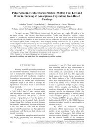
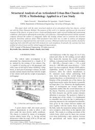
Strojniški vestnik - Journal <strong>of</strong> Mechanical Eng<strong>in</strong>eer<strong>in</strong>g 57(2011)7-8, 622-632whereK th* = M T · K th · M,C th* = M T · C th · M.(14a)(14b)The system <strong>of</strong> Eq. (13) conta<strong>in</strong>s N uncoupledequations,Λψii + siψi= ,( i = 12 , ,..., N),(15)*C iith* th*where s i = K ii / Ciiand Λ = M T (F th + F γth).The <strong>in</strong>itial condition ψ (0) can be obta<strong>in</strong>ed fromT(0) = M · ψ(0). Depend<strong>in</strong>g on the complexity <strong>of</strong>the right-hand side <strong>of</strong> Eq. (15), it is solved eitheranalytically or numerically.5 NUMERICAL RESULTS ANDDISSCUSSIONIn this section, the calculation <strong>of</strong> the mode ISIF for an edge crack <strong>in</strong> functionally graded plate(FGP) under thermal stresses is considered. Inaddition, a few parametric analyses are performedto study the effect <strong>of</strong> the gradation <strong>of</strong> materialproperties on the stress <strong>in</strong>tensity factor. Thedistribution <strong>of</strong> material properties is determ<strong>in</strong>edby means <strong>of</strong> cont<strong>in</strong>uum functions e.g., exponentialfunction or micromechanics models e.g., selfconsistentmodel. Examples are presented here:• An edge cracked plate: exponential gradation.• FGP with an edge crack: power law gradation.• Edge crack <strong>in</strong> an FGP: micromechanicsmodel.The FGP <strong>of</strong> length W and height H witha crack <strong>of</strong> length a, as depicted <strong>in</strong> Fig. 1a, isconsidered. The thickness (<strong>in</strong> the x 3 direction) <strong>of</strong>the plate is assumed to be quite th<strong>in</strong> for plane stressanalysis and large enough for plane stra<strong>in</strong> analysis.The crack is aligned parallel to the direction <strong>of</strong>material property gradation. Initially, the FGP is ata uniform stress-free temperature T 0 . Temperatures<strong>of</strong> x 1 = 0 and x 1 = W faces are decreased to constanttemperatures T 1 and T 2 , respectively. All otherfaces, <strong>in</strong>clud<strong>in</strong>g the crack surfaces, are assumed tobe <strong>in</strong>sulated, which results <strong>in</strong> a dimensional heatconduction problem <strong>in</strong> the x 1 direction. In all cases,the calculated SIFs will be normalized by divid<strong>in</strong>gto:K = E( 0) α( 0) T πa( 1−ν ( 0)).(16)0 05.1. An Edge Cracked Plate with ExponentiallyGradationFig. 1a shows an unconstra<strong>in</strong>ed FGP withan edge crack <strong>of</strong> length a, Fig. 1b presents thecomplete node arrangement <strong>of</strong> the FGP whichconsists <strong>of</strong> 1695 regular nodes and 40 crack-tipnodes, with a total <strong>of</strong> 1735. Fig. 1c shows thecrack-tip node arrangement. In this case, twodifferent types <strong>of</strong> functionally graded materialsare considered with exponentially vary<strong>in</strong>gthermomechanical properties (E, ν, α, k, ρc), <strong>in</strong> thex 1 direction, e.g.:Ex ( ) = E( 0)exp( P x ), (17)1 E 1where the nonhomogeniety parameters are def<strong>in</strong>ede.g., as:EWPE = 1 ⎛ ( ) ⎞ln ⎜ ⎟. (18)W ⎝ E( 0)⎠Fig. 1. An FGM plate with an edge crack;a) geometry, b) complete node arrangement, c)crack-tip node arrangementThe values <strong>of</strong> the nonhomogeneityparameters for the first material are selectedarbitrarily (academic materials) as they followto provide conditions for which the referencessolutions are available.E(0) = k(0) = α(0) = ρc(0) = 1.0, ν(0) = 0.3.For the second case, the ceramic/metalFGM ZrO 2 /Ti-6Al-4V material with properties <strong>of</strong>Table 1 is assumed.<strong>Computation</strong> <strong>of</strong> <strong>Stress</strong> <strong>Intensity</strong> <strong>Factor</strong> <strong>in</strong> <strong>Functionally</strong> <strong>Graded</strong> <strong>Plates</strong> under Thermal Shock625
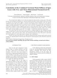
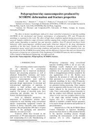
Strojniški vestnik - Journal <strong>of</strong> Mechanical Eng<strong>in</strong>eer<strong>in</strong>g 57(2011)7-8, 622-632For the sake <strong>of</strong> comparison, two differentcases <strong>of</strong> the thermal boundary conditions areconsidered <strong>in</strong> the steady-state analysis. In the thirdcase, a transient analysis is also carried out fordifferent temperatures at the left and right sides <strong>of</strong>the plate.In order to verify the implementation <strong>of</strong>DCT and EDI approaches <strong>in</strong> the framework <strong>of</strong>EFG method, comparisons <strong>of</strong> the calculated SIFsand the available reference solutions are firstpresented. In this case, the temperature <strong>of</strong> x 1 = 0and x 1 = W faces are decreased from T 0 to T 1 andT 2 , respectively. Table 2 compares the normalizedSIFs with the results provided by Erdogan andWu [4], KC and Kim [8] and Yildirim [6]. Theobta<strong>in</strong>ed solutions are <strong>in</strong> good agreement with thereferences. It is <strong>in</strong>terest<strong>in</strong>g to note that our modelis comprised <strong>of</strong> 1735 nodes, while the 2D meshdiscretization <strong>in</strong> KC and Kim [8] consists <strong>of</strong> 966elements and 2937 nodes <strong>in</strong> the framework <strong>of</strong> thef<strong>in</strong>ite element method.S<strong>in</strong>ce the surface crack is usually createddur<strong>in</strong>g cool<strong>in</strong>g, the FGP problem subjected toa cool<strong>in</strong>g shock is considered here. To considerthe thermal shock, it is assumed that the FGP is<strong>in</strong>itially at a uniform stress-free temperature T 0 andsuddenly cooled down to constant temperaturesT 1 = 0.2 T 0 and T 2 = 0.5 T 0 at the left and righthand side faces, respectively. The obta<strong>in</strong>ed resultsfor the transient temperature distribution <strong>in</strong> theZrO 2 /Ti-6Al-4V FGM versus normalized time τ,as def<strong>in</strong>ed <strong>in</strong> Eq. (19), is depicted <strong>in</strong> Fig. 2.ρτ = k ( 0) ( 0) c ( 0) t .(19)2WAccord<strong>in</strong>g to these results, the temperaturegradient near the plate edges is considerably largeat the early times after impos<strong>in</strong>g the thermalshock.Figs. 3 and 4 present normalized SIFs <strong>in</strong> theZrO 2 /Ti-6Al-4V plate result<strong>in</strong>g from the transienttemperature field versus the normalized time τ andthe normalized crack length a/W for plane stra<strong>in</strong>and plane stress cases, respectively. As shown <strong>in</strong>these figures, the SIF quickly <strong>in</strong>creases to a peakvalue that is drastically larger than the steady valueand then decreases rapidly to the correspond<strong>in</strong>gsteady value for all crack lengths. In addition, themagnitude <strong>of</strong> SIF decreases as the normalizedcrack length a/W becomes larger <strong>in</strong> both transientand steady states that are <strong>in</strong> agreement with theresults that have recently been reported by Nodaand Guo [5].Table 1. Material properties <strong>of</strong> ZrO 2 and Ti-6Al-4VMaterialsYoung'smodulus[GPa]Poisson'sratioCoefficient<strong>of</strong> thermalexpansion[10 -6 /K]Thermalconductivity[W/(m K)]Mass density[kg/m 3 ]Specific heat[J/(kg K)]ZrO 2 151.0 0.33 10.0 2.09 5331 456.7Ti-6Al-4V 116.7 0.33 9.5 7.5 4420 537.0Table 2. Normalized mode I SIF <strong>in</strong> FGP under steady-state thermal load<strong>in</strong>gNormalized SIFMaterialAnalysisLoadPresent Erdogan KC and YildirimparameterstypeEDI DCT and Wu [4] Kim [8] [6]T 1 = 0.5 T 0 Plane stra<strong>in</strong> 0.0124 0.0126 0.0125 0.0128 0.0128WP E =ln(5) T 2 = 0.5 T 0 Plane stress 0.0090 0.0088 - 0.0090 0.0090WP α =ln(2) T 1 = 0.05 T 0Plane stra<strong>in</strong> 0.0246 0.0240 0.0245 0.244 -T 2 = 0.05 T 0TWP E =ln(5) 1 = 0.2 T 0 Plane stra<strong>in</strong> 0.0334 0.0343 0.0335 0.0334 0.034TWP α =ln(2) 2 = 0.5 T 0 Plane stress 0.0234 0.0239 - 0.0235 0.024TWP k =ln(10) 1 = 0.05 T 0Plane stra<strong>in</strong> 0.0405 0.0411 0.0410 0.0406 -T 2 = 0.5 T 0626 Nazari, M.B. ‒ Shariati, M. ‒ Eslami, M.R. ‒ Hassani, B.
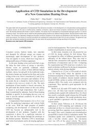
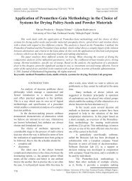
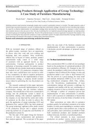
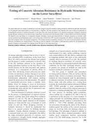
Strojniški vestnik - Journal <strong>of</strong> Mechanical Eng<strong>in</strong>eer<strong>in</strong>g 57(2011)7-8, 622-632Fig. 2. Transient temperature distribution <strong>in</strong> theFGP (ZrO 2 /Ti-6Al-4V) for various normalizedtimes with T 1 / T 0 = 0.2 and T 2 / T 0 = 0.5The exponent p is a positive constantused as an adjust<strong>in</strong>g parameter to obta<strong>in</strong> certa<strong>in</strong>distribution for material properties. As theexponent p can be chosen <strong>in</strong>dependently from thecomprised materials, this function is significantlyflexible and hence widely used <strong>in</strong> practice forthe analysis <strong>of</strong> the FGMs. In the proportionalmaterial properties, the exponent p is assumedthe same value for all material properties while itcan be selected differently for non-proportionalmaterials.Fig. 3. Normalized K I <strong>in</strong> the ZrO 2 /Ti-6Al-4Vplate versus normalized time and different cracklengths <strong>in</strong> plane stra<strong>in</strong> conditionAs the f<strong>in</strong>al po<strong>in</strong>t, the magnitude <strong>of</strong> SIF forthe plane stra<strong>in</strong> is larger than plane stress. Noda etal. [14] have derived thermal stresses analyticallyfor a homogeneous isotropic strip under onedimensionaltransient temperature distribution.These results <strong>in</strong>dicate that the thermal stresses forthe plane stra<strong>in</strong> case are equal to those <strong>of</strong> the planestress multiplied by a factor <strong>of</strong> 1/(1-ν). Regard<strong>in</strong>gthe fact 0 < ν < 0.5, this factor is greater than one,which implies a larger SIF for the plane stra<strong>in</strong> <strong>in</strong>comparison to the plane stress problem, which canbe noticed from Figs. 2 and 3.5.2. FGP with an Edge Crack with Power LawGradationA Ni/TiC plate with the configuration <strong>of</strong>the first example is considered here and a powerlawfunction is assumed to describe the materialproperties <strong>in</strong> the x 1 -direction e.g., as follows.Ex ( ) = E( 0) + ( E( W) − E( 0))( x / W) p . (20)1 1Fig. 4. Normalized K I <strong>in</strong> the ZrO 2 /Ti-6Al-4V plateversus normalized time for different crack lengths<strong>in</strong> plane stress conditionMoreover, here different thermal boundaryconditions are imposed on the uncracked face <strong>of</strong>FGP. To apply a thermal shock, the cracked face isassumed to be quenched to a constant temperature<strong>of</strong> T 1 = 0 while hav<strong>in</strong>g the free convection atthe other face with a convection coefficient <strong>of</strong>h=10 W/(m 2 K) and the ambient temperature isassumed T 0 . The transient temperature distribution<strong>in</strong> the Ni/TiC plate is presented <strong>in</strong> Fig. 5 for theproportional case with p = 5. The effect <strong>of</strong> theconvection boundary condition at the x 1 = Wface on the temperature distribution is moreapparent at the steady-state. Figs. 6 and 7 showthe transient thermal SIF versus crack lengthsfor the proportional case with p = 5 and p = 0.2,respectively. As can be seen, the variation <strong>of</strong> thethermal SIF is completely different for these cases.In the ceramic-riched case (p = 5), at the beg<strong>in</strong>n<strong>in</strong>g<strong>of</strong> the thermal shock the SIF <strong>in</strong>creases to a peakvalue and decl<strong>in</strong>es to its m<strong>in</strong>imum quickly andthen <strong>in</strong>crease gradually to a steady-state value.However, <strong>in</strong> the metal-riched case (p = 0.2)the SIF <strong>in</strong>creases quickly to a peak value and thendecreases rapidly until the crack is closed. The<strong>Computation</strong> <strong>of</strong> <strong>Stress</strong> <strong>Intensity</strong> <strong>Factor</strong> <strong>in</strong> <strong>Functionally</strong> <strong>Graded</strong> <strong>Plates</strong> under Thermal Shock627
Strojniški vestnik - Journal <strong>of</strong> Mechanical Eng<strong>in</strong>eer<strong>in</strong>g 57(2011)7-8, 622-632Table 3. Material properties <strong>of</strong> Ni and TiCMaterialsYoung’smodulus[GPa]Poisson’sratioCoefficient<strong>of</strong> thermalexpansion[10 -6 /K]Thermalconductivity[W/(m K)]Mass density[kg/m 3 ]Specific heat[J/(kg K)]TiC 320 0.195 7.4 25.1 4940 134Ni 206 0.312 13.3 90.5 8890 439.5correspond<strong>in</strong>g time <strong>of</strong> the crack closure <strong>in</strong>creasesas the crack length is <strong>in</strong>creased. In this example,the crack closure occurred <strong>in</strong> steady-state for allcrack lengths.condition. Accord<strong>in</strong>g to these results, whilethe value <strong>of</strong> the SIF is <strong>in</strong>dependent <strong>of</strong> the type<strong>of</strong> the thermal boundary condition applied onthe uncracked face, the steady-state value iscompletely dependent. Moreover, a greater valuefor the steady-state SIF is obta<strong>in</strong>ed for the case <strong>of</strong>constant temperature at both faces.Fig. 5. Transient temperature distribution <strong>in</strong> theFGP (Ni/TiC) for various normalized times withT 1 = 0 and h = 10Fig. 7. Normalized K I <strong>in</strong> the Ni/TiC plate versusnormalized time for different crack lengths <strong>in</strong>plane stra<strong>in</strong> condition and p = 0.2Fig. 6. Normalized K I <strong>in</strong> the Ni/TiC plate versusnormalized time and different crack lengths <strong>in</strong>plane stra<strong>in</strong> condition and p = 5The effect <strong>of</strong> the thermal boundarycondition applied on the uncracked face for thel<strong>in</strong>ear proportional material i.e., p = 1, is illustrated<strong>in</strong> the Fig. 8. Here, the h = 0 corresponds to the<strong>in</strong>sulated thermal boundary condition and h = ∞corresponds to a known temperature boundaryFig. 8. The effect <strong>of</strong> thermal boundary conditionat x 1 = W on the variation <strong>of</strong> normalized K INow, the effect <strong>of</strong> the material gradationis studied and some parametric analyses arecarried out to assess their effect on the SIFs. Inall cases, it is assumed that the exponent p getsdifferent values for the special property and628 Nazari, M.B. ‒ Shariati, M. ‒ Eslami, M.R. ‒ Hassani, B.
Strojniški vestnik - Journal <strong>of</strong> Mechanical Eng<strong>in</strong>eer<strong>in</strong>g 57(2011)7-8, 622-632p = 0.2 for other material properties. Figs. 9 and10 present the effect <strong>of</strong> variation <strong>in</strong> FGP elasticproperties, i.e. Young’s modulus and Poisson’sratio, on the SIF for the crack length a/W = 0.3and the plane stra<strong>in</strong> problem. Accord<strong>in</strong>g to Fig.9, the magnitude <strong>of</strong> SIF, especially its peak value,<strong>in</strong>creases significantly as the parameter p E is<strong>in</strong>creased. These results <strong>in</strong>dicate that for all values<strong>of</strong> p E , the peak and the crack closure time occurroughly simultaneously. This can be expla<strong>in</strong>ed bythe fact that the transient temperature distributionis <strong>in</strong>dependent <strong>of</strong> the variations <strong>of</strong> the parameterp E . We believe that the effect <strong>of</strong> Young’s modulusis responsible for the slight difference between thepeak time and the steady time.The <strong>in</strong>fluence <strong>of</strong> Poisson’s ratio gradationon the SIF is shown <strong>in</strong> Fig. 10. It can be seen that,by a decrease <strong>in</strong> p ν , i.e. for metal-riched whosegreater Poisson’s ratio, the magnitude <strong>of</strong> SIF andthe crack closure time <strong>in</strong>crease.The analytical solutions for thermal stressdistribution <strong>in</strong> an uncracked FGP under onedimensionaltemperature distribution for the planestra<strong>in</strong> and plane stress cases are given as [4]:σthxx 2 2andσEx ( 1)= ( Cx C α x ν T x t2 1 1+ 2 − ( 1)( 1+) ∆ ( 1, ), ) (21a)1 − ν( )thxx 2 2 1 1 1 2 1 1= Ex ( ) Cx + C −α( x ) ∆ T( x , t),(21b)The effects <strong>of</strong> the gradation <strong>of</strong> the thermalproperties on the SIF dur<strong>in</strong>g the shock period areshown <strong>in</strong> Figs. 11, 12 and 13. Fig. 11 depicts thenormalized SIF versus normalized time for variousvalues <strong>of</strong> the exponent p for the thermal expansioncoefficient, i.e., p α . Accord<strong>in</strong>g to this figure, thepeak value <strong>of</strong> SIF for the case p = 0.2 is significantlygreater than others. Also, depend<strong>in</strong>g on the p αvalue, the trend <strong>of</strong> SIF might be completelydifferent. For example, the crack is closed for thep α = 0.2 and p α = 1 cases, while the SIF for p α = 5<strong>in</strong>creases gradually to a steady-state value after itpeaks and reduces to a local m<strong>in</strong>imum.Fig. 10. Normalized K I versus normalized timefor different p ν ; plane stra<strong>in</strong> with a/W = 0.3,p = 0.2 for other material propertiesrespectively, where C 1 and C 2 are unknowncoefficients determ<strong>in</strong>ed from the force and momentboundary conditions <strong>in</strong> the x 2 direction. From Eq.(21), it is observed that the thermal stresses are an<strong>in</strong>creas<strong>in</strong>g function <strong>of</strong> Young’s modulus.Fig. 11. Normalized K I versus normalized timefor different p α values; plane stra<strong>in</strong> witha/W = 0.3, p = 0.2 for other material propertiesFig. 9. Normalized K I versus normalized time fordifferent p E ; plane stra<strong>in</strong> with a/W = 0.3, p = 0.2for other material propertiesFig. 12 illustrates the SIF variation <strong>in</strong>terms <strong>of</strong> time for various values <strong>of</strong> conductivityparameter p k . It can be seen that an <strong>in</strong>crease <strong>of</strong> theparameter p k causes a delay <strong>in</strong> the occurrence <strong>of</strong>the peak value <strong>of</strong> SIF and steady-state. This delayis not surpris<strong>in</strong>g s<strong>in</strong>ce the diffusivity k/ρc is an<strong>in</strong>creas<strong>in</strong>g function <strong>of</strong> the conductivity and thep k = 0.2 correspond to metal-riched composition<strong>Computation</strong> <strong>of</strong> <strong>Stress</strong> <strong>Intensity</strong> <strong>Factor</strong> <strong>in</strong> <strong>Functionally</strong> <strong>Graded</strong> <strong>Plates</strong> under Thermal Shock629
Strojniški vestnik - Journal <strong>of</strong> Mechanical Eng<strong>in</strong>eer<strong>in</strong>g 57(2011)7-8, 622-632with greater conductivity, Moreover, for ceramicrichedcase (p k = 5) the peak value <strong>of</strong> SIF and thecrack closure time is greater than the metal-richedcase. The variation <strong>of</strong> SIF with the normalizedtime and the nonhomogeniety parameter <strong>of</strong> ρc ispresented <strong>in</strong> Fig. 13. These results <strong>in</strong>dicate that thepeak value <strong>of</strong> SIF is almost <strong>in</strong>dependent from p ρc .The peak time and the crack closure time <strong>in</strong>creasefor the ceramic-riched case (p ρc = 5).Fig. 12. Normalized K I versus normalized timefor different p k . Plane stra<strong>in</strong> with a/W = 0.3,p = 0.2 for other material propertiesFig. 13. Normalized K I versus normalized timefor different p ρc values; plane stra<strong>in</strong> witha/W = 0.3, p = 0.2 for other material propertiesa benefit for relate optimal property distributions.Moreover, <strong>in</strong> this method the properties aredeterm<strong>in</strong>ed <strong>in</strong>dependently <strong>of</strong> the phase <strong>of</strong> the<strong>in</strong>clusion and the matrix. This is significantfor FGMs <strong>in</strong> which the volume fraction <strong>of</strong> theconstituent phases varies <strong>in</strong> a wide range. For twophaseFGMs, the volume fraction <strong>of</strong> the ceramicis assumed <strong>in</strong> the form <strong>of</strong> a power function, i.e.V c = 1‒(x 1 /L) p , <strong>in</strong> which L is the material gradationlength and the exponent p is known as the gradient<strong>in</strong>dex. Here x 1 = 0 corresponds to pure matrixphase (ceramic) and x 1 = L to pure <strong>in</strong>clusionmaterial (metal). For a two-phase composite, theeffective materials are determ<strong>in</strong>ed from [16],1 VcVm= + , (22a)κ + 4µ / 3 κ + 4µ / 3 κ + 4µ/ 3c⎛ Vcκc Vmκm⎞⎜ + ⎟ +⎝ κ c + 4µ/ 3 κ m + 4µ/ 3⎠⎛ Vcµm Vmµc⎞+ 5⎜+ ⎟ + 2=0, (22b)⎝ µ − µ m µ − µ c ⎠( αc −αm)( 1/ κ −1/ κm)α = αm+,( 1/ κ −1/ κ )cmm(22c)Vm( km− k) Vc( kc− k)+ = 0 . (22d)k + 2kk + 2kmWe consider an edge crack <strong>in</strong> anunconstra<strong>in</strong>ed FGP <strong>of</strong> length W and height H = 8W. To consider the thermal shock, it is assumedthat only the cracked face <strong>of</strong> the FGP is suddenlycooled down to constant temperature T 1 = 0 fromthe stress-free temperature T 0 . Fig. 14 presentsthe transient temperature distribution <strong>in</strong> the FGP.Here, it is assumed that ΔT = T(x 1 ,t) ‒ T 0 .c5.3 Edge Crack <strong>in</strong> an FGP with MicromechanicsModelPrediction <strong>of</strong> the effective macroscopicproperties is one <strong>of</strong> the basic issues <strong>in</strong> compositematerial theory. For FGMs, as the gradedcomposites, some micromechanics models <strong>of</strong>composites have been developed. Among manymicromechanics models extended for FGMs, selfconsistentmethod (SCM) was used. Zuiker [16]has po<strong>in</strong>ted out that the SCM provides a simpleand <strong>in</strong>itial estimate <strong>of</strong> effective properties which isFig. 14. Transient temperature distribution <strong>in</strong> theFGP for various normalized times with T 1 =0630 Nazari, M.B. ‒ Shariati, M. ‒ Eslami, M.R. ‒ Hassani, B.
Strojniški vestnik - Journal <strong>of</strong> Mechanical Eng<strong>in</strong>eer<strong>in</strong>g 57(2011)7-8, 622-6324. Comparison <strong>of</strong> the obta<strong>in</strong>ed numerical resultswith the reference solutions <strong>in</strong>dicates thatboth energy-based EDI and direct approachDCT methods, <strong>in</strong> the framework <strong>of</strong> enrichedEFG, are efficient tools to analyze the thermalfracture <strong>of</strong> FGMs.7 REFERENCESFig. 15. Normalized mode I stress <strong>in</strong>tensity factor<strong>in</strong> the FGP versus normalized time and differentcrack lengths <strong>in</strong> plane stra<strong>in</strong> conditionFig. 15 depicts the transient thermal SIFversus normalized crack lengths a/W for planestra<strong>in</strong> case. Although the steady value <strong>of</strong> SIF isgreater for longer cracks, the peak value <strong>of</strong> SIF issignificantly large for short cracks.6 CONCLUSIONIn this paper, the doma<strong>in</strong> form <strong>of</strong> J-<strong>in</strong>tegral(EDI) and displacement correlation technique(DCT) <strong>in</strong> conjunction with element-free Galerk<strong>in</strong>method are implemented to evaluate the mode Istress <strong>in</strong>tensity factor <strong>in</strong> FGMs under steady-stateand transient temperature fields. The present studypo<strong>in</strong>ts out that:1. In the enriched EFG framework a relativelycoarse mesh <strong>in</strong> compared with FEM andcommon XFEM is sufficient for analysis <strong>of</strong>cracks <strong>in</strong> FGMs under thermal load<strong>in</strong>g.2. A short while after the thermal shock, SIF<strong>in</strong>creases to a large peak value, which issignificantly greater than the correspond<strong>in</strong>gsteady value and then decreases rapidly to asteady value. Moreover, although the crackis closed at steady state for some cases, thevalue <strong>of</strong> SIF might reach to a large positivevalue dur<strong>in</strong>g the thermal shock period. Theseimply that <strong>in</strong> thermal fracture analysis <strong>of</strong>FGMs, the SIF at the beg<strong>in</strong>n<strong>in</strong>g <strong>of</strong> thermalload<strong>in</strong>g might be the ma<strong>in</strong> factor <strong>in</strong> fracturefailure analysis.3. Parametric analyses <strong>in</strong>dicate that thevariation <strong>in</strong> the thermomechanical properties,especially thermal characteristics, hasa significantly <strong>in</strong>fluence on the fracturebehaviour <strong>of</strong> FGMs.[1] Kawasaki, A., Watanabe, R. (2002).Thermal fracture behavior <strong>of</strong> metal/ceramicfunctionally graded materials. Eng<strong>in</strong>eer<strong>in</strong>gFracture Mechanics, vol. 69, p. 1713-1728.[2] J<strong>in</strong>, Z-H., Noda, N. (1994). Crack-tip s<strong>in</strong>gularfields <strong>in</strong> nonhomogeneous materials. Journal<strong>of</strong> Applied Mechanics, Transactions ASME,vol. 61, p. 738-740.[3] Kishimoto, K., Aoki, S., Sakata, M.(1980). On the path <strong>in</strong>dependent J-<strong>in</strong>tegral.Eng<strong>in</strong>eer<strong>in</strong>g Fracture Mechanics, vol. 13, p.841-850.[4] Erdogan, F., Wu, B.H. (1996). Crackproblems <strong>in</strong> FGM layers under thermalstresses. Journal <strong>of</strong> Thermal <strong>Stress</strong>es, vol. 19,p. 237-265.[5] Noda, N., Guo, L.C. (2008). Thermal shockanalysis for a functionally graded plate witha surface crack. Acta Mechanica, vol. 195, p.157-166.[6] Yildirim, B. (2006). An equivalent doma<strong>in</strong><strong>in</strong>tegral method for fracture analysis <strong>of</strong>functionally graded materials under thermalstresses. Journal <strong>of</strong> Thermal <strong>Stress</strong>es, vol. 29,p. 371-397.[7] Dag, S. (2006). Thermal fracture analysis<strong>of</strong> orthotropic functionally graded materialsus<strong>in</strong>g an equivalent doma<strong>in</strong> <strong>in</strong>tegral approach.Eng<strong>in</strong>eer<strong>in</strong>g Fracture Mechanics, vol. 73, p.2802-2828.[8] KC, A., Kim, J.H. (2008). Interaction <strong>in</strong>tegralsfor thermal fracture <strong>of</strong> functionally gradedmaterials. Eng<strong>in</strong>eer<strong>in</strong>g Fracture Mechanics,vol. 75, p. 2542-2565.[9] Kim, J.H., KC, A. (2008). A Generalized<strong>in</strong>teraction <strong>in</strong>tegral method for the evaluation<strong>of</strong> the T-stress <strong>in</strong> orthotropic functionallygraded materials under thermal load<strong>in</strong>g.Journal <strong>of</strong> Applied Mechanics, vol. 75, p.1-11.<strong>Computation</strong> <strong>of</strong> <strong>Stress</strong> <strong>Intensity</strong> <strong>Factor</strong> <strong>in</strong> <strong>Functionally</strong> <strong>Graded</strong> <strong>Plates</strong> under Thermal Shock631
Strojniški vestnik - Journal <strong>of</strong> Mechanical Eng<strong>in</strong>eer<strong>in</strong>g 57(2011)7-8, 622-632[10] Chen, J. (2005). Determ<strong>in</strong>ation <strong>of</strong> thermalstress <strong>in</strong>tensity factors for an <strong>in</strong>terface crack<strong>in</strong> a graded orthotropic coat<strong>in</strong>g-substratestructure. International Journal <strong>of</strong> Fracture,vol. 133, p. 303-328.[11] Rao, B.N., Rahman, S. (2003). Mesh-freeanalysis <strong>of</strong> cracks <strong>in</strong> isotropic functionallygraded materials. Eng<strong>in</strong>eer<strong>in</strong>g FractureMechanics, vol. 70, p. 1-27.[12] Flem<strong>in</strong>g, M., Chu, Y.A., Moran, B.,Belytschko, T. (1997). Enriched elementfreegalerk<strong>in</strong> methods for crack tip fields.International Journal for Numerical Methods<strong>in</strong> Eng<strong>in</strong>eer<strong>in</strong>g, vol. 40, p. 1483-1504.[13] Rice, J.R. (1968). A path <strong>in</strong>dependent <strong>in</strong>tegraland the approximate analysis <strong>of</strong> stra<strong>in</strong>concentration by notches and cracks. Journal<strong>of</strong> Applied Mechanics, vol. 35, p. 379-386.[14] Zienkiewics, O.C., Taylor, R.L. (2000).The F<strong>in</strong>ite Element Method. Butterworth-He<strong>in</strong>emann, Oxford.[15] Noda, N., Hetnarski, R.B., Tanigawa, Y.(2003). Thermal <strong>Stress</strong>es. Taylor and Francis,New York.[16] Zuiker, J.R. (1995). <strong>Functionally</strong> gradedmaterials: choice <strong>of</strong> micromechanics modeland limitations <strong>in</strong> property variation.Composites Eng<strong>in</strong>eer<strong>in</strong>g, vol. 5, p. 807-819.632 Nazari, M.B. ‒ Shariati, M. ‒ Eslami, M.R. ‒ Hassani, B.