Numerical Modelling of Crack Growth in a Gear Tooth Root
Numerical Modelling of Crack Growth in a Gear Tooth Root
Numerical Modelling of Crack Growth in a Gear Tooth Root

You also want an ePaper? Increase the reach of your titles
YUMPU automatically turns print PDFs into web optimized ePapers that Google loves.
Strojniški vestnik - Journal <strong>of</strong> Mechanical Eng<strong>in</strong>eer<strong>in</strong>g 57(2011)7-8, 579-586 Paper received: 15.09.2009<br />
DOI:10.5545/sv-jme.2009.127 Paper accepted: 16.05.2011<br />
<strong>Numerical</strong> <strong>Modell<strong>in</strong>g</strong> <strong>of</strong> <strong>Crack</strong> <strong>Growth</strong> <strong>in</strong> a <strong>Gear</strong> <strong>Tooth</strong> <strong>Root</strong><br />
Podrug, S. ‒ Glodež, S. ‒ Jelaska, D.<br />
Srđan Podrug 1 ‒ Srečko Glodež 2,* ‒ Damir Jelaska 1<br />
1 University <strong>of</strong> Split, Faculty <strong>of</strong> Electrical Eng<strong>in</strong>eer<strong>in</strong>g, Mechanical Eng<strong>in</strong>eer<strong>in</strong>g<br />
and Naval Architecture, Croatia<br />
2 University <strong>of</strong> Maribor, Faculty <strong>of</strong> Natural Science and Mathematics, Slovenia<br />
A computational model for determ<strong>in</strong>ation <strong>of</strong> crack growth <strong>in</strong> a gear tooth root is presented. Two<br />
load<strong>in</strong>g conditions are taken <strong>in</strong>to account: (i) normal pulsat<strong>in</strong>g force act<strong>in</strong>g at the highest po<strong>in</strong>t <strong>of</strong> the<br />
s<strong>in</strong>gle tooth contact and (ii) the mov<strong>in</strong>g load along the tooth flank. In numerical analysis it is assumed<br />
that the crack is <strong>in</strong>itiated at the po<strong>in</strong>t <strong>of</strong> the largest stresses <strong>in</strong> a gear tooth root. The simple Paris equation<br />
is then used for a further simulation <strong>of</strong> the fatigue crack growth. The functional relationship between the<br />
the stress <strong>in</strong>tensity factor and crack length K = f(a), which is needed for determ<strong>in</strong><strong>in</strong>g the required number<br />
<strong>of</strong> load<strong>in</strong>g cycles N for a crack propagation from the <strong>in</strong>itial to the critical length, is obta<strong>in</strong>ed us<strong>in</strong>g a<br />
displacement correlation method <strong>in</strong> the framework <strong>of</strong> the FEM-method consider<strong>in</strong>g the effect <strong>of</strong> crack<br />
closure. The model is used for determ<strong>in</strong><strong>in</strong>g fatigue crack growth <strong>in</strong> a real gear made from case carburised<br />
and ground steel 14CiNiMo13-4, where the required material parameters were determ<strong>in</strong>ed previously<br />
by appropriate test specimens. The results <strong>of</strong> the numerical analysis show that the prediction <strong>of</strong> crack<br />
propagation live and crack path <strong>in</strong> a gear tooth root are significantly different for both load<strong>in</strong>g conditions<br />
considered.<br />
© 2011 Journal <strong>of</strong> Mechanical Eng<strong>in</strong>eer<strong>in</strong>g. All rights reserved.<br />
Keywords: gears, fatigue, crack growth, numerical modell<strong>in</strong>g<br />
0 INTRODUCTION<br />
Two k<strong>in</strong>ds <strong>of</strong> teeth damage can occur on<br />
gears under repeated load<strong>in</strong>g due to fatigue; the<br />
pitt<strong>in</strong>g <strong>of</strong> gear teeth flanks and tooth breakage<br />
<strong>in</strong> the tooth root [1]. In this paper only the<br />
tooth breakage is addressed and the developed<br />
computational model is used for the calculation <strong>of</strong><br />
tooth bend<strong>in</strong>g strength, i.e. the service life <strong>of</strong> gear<br />
tooth root.<br />
The standardised procedures accord<strong>in</strong>g<br />
to ISO-standards [1] are usually used for an<br />
approximate determ<strong>in</strong>ation <strong>of</strong> load capacity<br />
<strong>of</strong> gear tooth root. They are commonly based<br />
on the comparison <strong>of</strong> the maximum tooth-root<br />
stress with the permissible bend<strong>in</strong>g stress. Their<br />
determ<strong>in</strong>ation depends on a number <strong>of</strong> different<br />
coefficients that allow for proper consideration <strong>of</strong><br />
real work<strong>in</strong>g conditions (additional <strong>in</strong>ternal and<br />
external dynamic forces, contact area <strong>of</strong> engag<strong>in</strong>g<br />
gears, gear material, surface roughness, etc.). The<br />
standardised procedures are exclusively based on<br />
the experimental test<strong>in</strong>g <strong>of</strong> the reference gears and<br />
they consider only the f<strong>in</strong>al stage <strong>of</strong> the fatigue<br />
process <strong>in</strong> the gear tooth root, i.e. the occurrence<br />
<strong>of</strong> f<strong>in</strong>al failure.<br />
*Corr. Author’s Address: University <strong>of</strong> Maribor, Faculty <strong>of</strong> Natural Science and Mathematics,<br />
Koroška 160, 2000 Maribor, Slovenia srecko.glodez@uni-mb.si<br />
However, the complete process <strong>of</strong> fatigue<br />
failure may be divided <strong>in</strong>to the “crack <strong>in</strong>itiation”<br />
and “crack propagation” period [2] and [3]. An<br />
exact def<strong>in</strong>ition <strong>of</strong> the transition from <strong>in</strong>itiation<br />
to propagation period is usually not possible.<br />
However, the crack <strong>in</strong>itiation period generally<br />
accounts for most <strong>of</strong> the service life, especially<br />
<strong>in</strong> high-cycle fatigue, see Fig. 1. The complete<br />
service life <strong>of</strong> mechanical elements N can than<br />
be determ<strong>in</strong>ed from the number <strong>of</strong> stress cycles<br />
N i required for the fatigue crack <strong>in</strong>itiation and the<br />
number <strong>of</strong> stress cycles N p required for a crack<br />
to propagate from the <strong>in</strong>itial to the critical crack<br />
length, when the f<strong>in</strong>al failure can be expected to<br />
occur:<br />
N = Ni + N p . (1)<br />
The presented work is ma<strong>in</strong>ly restricted on<br />
the period <strong>of</strong> the fatigue crack growth, neglect<strong>in</strong>g<br />
or merely with experimental determ<strong>in</strong>ation <strong>of</strong><br />
the fatigue crack <strong>in</strong>itiation period. In most <strong>of</strong><br />
recent <strong>in</strong>vestigations [3] to [8] a load<strong>in</strong>g cycle<br />
<strong>of</strong> gear mesh<strong>in</strong>g is presumed as pulsat<strong>in</strong>g act<strong>in</strong>g<br />
at the highest po<strong>in</strong>t <strong>of</strong> the s<strong>in</strong>gle tooth contact.<br />
However, <strong>in</strong> actual gear operation, the magnitude<br />
as well as the position <strong>of</strong> the force, changes as the<br />
579
Strojniški vestnik - Journal <strong>of</strong> Mechanical Eng<strong>in</strong>eer<strong>in</strong>g 57(2011)7-8, 579-586<br />
gear rotates. This fact can be taken <strong>in</strong>to account<br />
perform<strong>in</strong>g a quasi static numerical simulation<br />
<strong>in</strong> which the gear tooth engagement is broken<br />
down <strong>in</strong>to multiple load steps and analyzed<br />
separately. In such a way, a more realistic stress<br />
cycle <strong>in</strong> the gear tooth root is obta<strong>in</strong>ed result<strong>in</strong>g <strong>in</strong><br />
significantly more exact assessment <strong>of</strong> the crack<br />
propagation life, and consequently <strong>in</strong> the entire<br />
fatigue life.<br />
Dσ<br />
<strong>Crack</strong> <strong>in</strong>itiation<br />
period Ni<br />
<strong>Crack</strong> propagation<br />
period Np<br />
DσFL<br />
log N<br />
Fig. 1. Schematic representation <strong>of</strong> the service life<br />
N <strong>of</strong> mechanical elements<br />
In this paper, a similar procedure to the one<br />
described <strong>in</strong> [8] for bevel gears, is used to analyse<br />
fatigue crack growth. However, it is appropriately<br />
modified and adopted for spur gears. An approach<br />
that accounts for fatigue crack closure effects<br />
is developed to propagate crack under nonproportional<br />
load.<br />
1 CRACK INITIATION SIZE<br />
In order to calculate the number <strong>of</strong> stress<br />
cycles required for a crack to propagate from the<br />
<strong>in</strong>itial to the critical crack length it is necessary to<br />
determ<strong>in</strong>e fatigue crack <strong>in</strong>itiation size. Although<br />
there have been many approaches to determ<strong>in</strong>e<br />
crack <strong>in</strong>itiation size, there has so far been no<br />
perfect approach. One <strong>of</strong> the most convenient<br />
representation <strong>of</strong> determ<strong>in</strong><strong>in</strong>g the crack <strong>in</strong>itiation<br />
size is the Kitagawa-Takahashi plot <strong>of</strong> applied<br />
stress range required for crack growth, Δσ, aga<strong>in</strong>st<br />
crack length, a, us<strong>in</strong>g logarithmic scales, as shown<br />
<strong>in</strong> Fig. 2 [9]. As the transition po<strong>in</strong>t between<br />
crack <strong>in</strong>itiation and crack propagation period<br />
the threshold crack length a th is selected, below<br />
which l<strong>in</strong>ear elastic fracture mechanics (LEFM) is<br />
580 Podrug, S. ‒ Glodež, S. ‒ Jelaska, D.<br />
not valid. For eng<strong>in</strong>eer<strong>in</strong>g applications empirical<br />
formula for this transition po<strong>in</strong>t is proposed [10]:<br />
2<br />
1 ⎛ ∆Kth<br />
⎞<br />
ath<br />
≈ ⎜ ⎟ , (2)<br />
π ⎝ ∆σFL<br />
⎠<br />
where Δσ FL is the fatigue limit and DK th is the<br />
threshold stress <strong>in</strong>tensity range. The threshold<br />
crack length a th thus def<strong>in</strong>es the transition po<strong>in</strong>t<br />
between short and long cracks, i.e. the transition<br />
po<strong>in</strong>t between <strong>in</strong>itiation and propagation period <strong>in</strong><br />
eng<strong>in</strong>eer<strong>in</strong>g applications. However, a wider range<br />
<strong>of</strong> values has been selected for a th <strong>in</strong> the literature,<br />
usually between 0.05 and 1 mm for steels where<br />
high strength steels take the smallest values [10]<br />
and [11].<br />
log Dσ<br />
Short crack<br />
regime<br />
DKth<br />
Fatigue limit DσFL<br />
Non propagat<strong>in</strong>g cracks<br />
Propagat<strong>in</strong>g<br />
cracks<br />
Long crack<br />
regime (LEFM)<br />
ath log a<br />
Fig. 2. Kitagawa-Takahashi plot<br />
2 FATIGUE CRACK PROPAGATION<br />
The application <strong>of</strong> the l<strong>in</strong>ear elastic<br />
fracture mechanics (LEFM) to fatigue is based<br />
upon the assumption that the fatigue crack growth<br />
rate, da/dN, is a function <strong>of</strong> stress <strong>in</strong>tensity range<br />
DK = Kmax-Km<strong>in</strong>, where a is a crack length and N<br />
is a number <strong>of</strong> load cycles. In this study the simple<br />
Paris equation is used to describe the crack growth<br />
rate:<br />
d a<br />
m<br />
= C[ ∆ K( a) ] .<br />
(3)<br />
d N<br />
This equation <strong>in</strong>dicates that the required<br />
number <strong>of</strong> load<strong>in</strong>g cycles Np for a crack to<br />
propagate from the <strong>in</strong>itial length ath to the critical<br />
crack length ac can be explicitly determ<strong>in</strong>ed, if C,<br />
m and DK(a) are known. C and m are the material<br />
parameters and can be obta<strong>in</strong>ed experimentally,
Strojniški vestnik - Journal <strong>of</strong> Mechanical Eng<strong>in</strong>eer<strong>in</strong>g 57(2011)7-8, 579-586<br />
usually by means <strong>of</strong> a three po<strong>in</strong>t bend<strong>in</strong>g test<br />
accord<strong>in</strong>g to the standard procedure ASTM E 399-<br />
80 [12]. For simple cases the dependence between<br />
the stress <strong>in</strong>tensity range and the crack length<br />
DK(a) can be determ<strong>in</strong>ed analytically as described<br />
<strong>in</strong> [11] and [12]. For a more complicated geometry<br />
and load<strong>in</strong>g cases it is necessary to use alternative<br />
methods. In this work the f<strong>in</strong>ite element method<br />
(FEM) <strong>in</strong> the framework <strong>of</strong> the program package<br />
FRANC2D [13], has been used for simulation<br />
<strong>of</strong> the fatigue crack growth, s<strong>in</strong>ce the uniformly<br />
distributed load on the tooth flank is assumed,<br />
which enables the usage <strong>of</strong> two-dimensional f<strong>in</strong>ite<br />
element mesh.<br />
A different method can be used to determ<strong>in</strong>e<br />
the equivalent stress <strong>in</strong>tensity range DK eq under<br />
mixed mode load<strong>in</strong>g as appears when load is<br />
mov<strong>in</strong>g on the gear tooth [14] to [22]. In presented<br />
work the follow<strong>in</strong>g equation is used to determ<strong>in</strong>e<br />
the equivalent stress <strong>in</strong>tensity range:<br />
2 θ0 ⎡ θ0 θ0<br />
⎤<br />
D Keq= cos KIcos3KIIs<strong>in</strong> ,<br />
2<br />
⎢D - D<br />
2 2<br />
⎥<br />
⎣ ⎦ (4)<br />
where θ 0 is the crack-propagation angle and DK I<br />
and DK II are the stress <strong>in</strong>tensity ranges for mode I<br />
and mode II, respectively.<br />
To analyse the fatigue crack growth under<br />
mix mode conditions the value DK <strong>in</strong> Eq. (3) has<br />
to be replaced with the value DK eq. The crackpropagation<br />
angle θ 0 is <strong>in</strong> this work determ<strong>in</strong>ed<br />
us<strong>in</strong>g maximum tensile stress criterion (MTScriterion)<br />
as follows:<br />
⎡ 2 ⎤<br />
-1<br />
1 KI ⎛ KI<br />
⎞<br />
θ0<br />
= 2 tan ⎢ ⋅ ± + 8 ⎥,<br />
⎢<br />
⎜ ⎟<br />
4 KII⎝ K ⎥<br />
II<br />
⎢<br />
⎠<br />
⎣ ⎥⎦<br />
(5)<br />
where K I and K II are the stress <strong>in</strong>tensity factors for<br />
mode I and mode II, respectively. The complete<br />
computational procedure <strong>of</strong> the fatigue crack<br />
propagation under mixed mode load<strong>in</strong>g conditions<br />
consider<strong>in</strong>g the crack closure effect is described <strong>in</strong><br />
[3], [23] and [24].<br />
3 COMPUTATIONAL MODEL<br />
In the proposed computational model,<br />
the uniformly load distribution along gear width<br />
is assumed, which enables the usage <strong>of</strong> two-<br />
<strong>Numerical</strong> <strong>Modell<strong>in</strong>g</strong> <strong>of</strong> <strong>Crack</strong> <strong>Growth</strong> <strong>in</strong> a <strong>Gear</strong> <strong>Tooth</strong> <strong>Root</strong><br />
dimensional f<strong>in</strong>ite element model. The model<br />
is manufactured with the aid <strong>of</strong> specifically<br />
developed s<strong>of</strong>tware, which on the basis <strong>of</strong><br />
geometrical parameters determ<strong>in</strong>es the rackgenerated<br />
gear tooth geometry. In order to capture<br />
the correct boundary conditions, one tooth on each<br />
side is <strong>in</strong>cluded <strong>in</strong> the model. Boundary conditions<br />
<strong>of</strong> the left and right hand edge portions are kept<br />
fixed, and s<strong>in</strong>ce solid gears are explored also the<br />
hub portions are kept fixed (Fig. 3). The distance<br />
between the root circle and the hub is taken to be<br />
<strong>of</strong> equal tooth height, so that the <strong>in</strong>fluence <strong>of</strong> the<br />
fixed hub on tooth base rotation can be neglected.<br />
Fig. 3. FE-model<br />
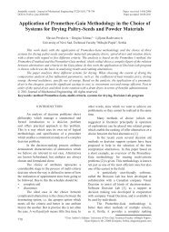
Two gear models are be<strong>in</strong>g explored (Fig.<br />
4): first <strong>in</strong> which gear tooth is loaded with normal<br />
pulsat<strong>in</strong>g force act<strong>in</strong>g at the highest po<strong>in</strong>t <strong>of</strong> the<br />
s<strong>in</strong>gle tooth contact (HPSTC), and second <strong>in</strong><br />
which the fact that <strong>in</strong> actual gear operation the<br />
magnitude as well as the position <strong>of</strong> the force<br />
changes as the gear rotates through the mesh, is<br />
taken <strong>in</strong>to account.<br />
Fig. 4. Load<strong>in</strong>g conditions; a) load act<strong>in</strong>g at the<br />
HPSTC, b) mov<strong>in</strong>g load<br />
581
Strojniški vestnik - Journal <strong>of</strong> Mechanical Eng<strong>in</strong>eer<strong>in</strong>g 57(2011)7-8, 579-586<br />
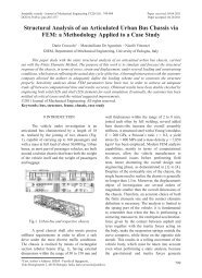
The computational analyses are performed<br />
for two different gear rim thickness s R <strong>in</strong> relation<br />
to the high <strong>of</strong> the tooth h (see Fig. 5):<br />
(i) s R = 3.3×h,<br />
(ii) s R = 0.3×h.<br />
Fig. 5. Different rim thickness <strong>of</strong> analysed gear;<br />
a) s R = 3.3×h, b) s R = 0.3×h<br />
3.1 Load Act<strong>in</strong>g at the HPSTC<br />
In that case a load<strong>in</strong>g cycle <strong>of</strong> mesh<strong>in</strong>g<br />
gears is presumed as pulsat<strong>in</strong>g force act<strong>in</strong>g at the<br />
HPSTC (Fig. 4a). The <strong>in</strong>itial crack <strong>of</strong> length a th<br />
calculated us<strong>in</strong>g Eq. (2) is placed at the critical<br />
plane, which is assumed to be perpendicular to the<br />
notch surface <strong>in</strong> a gear tooth root.<br />
3.2 Mov<strong>in</strong>g Load Model<br />
For a mov<strong>in</strong>g load model, a quasi static<br />
numerical simulation method is presented <strong>in</strong><br />
which the gear tooth engagement is broken down<br />
<strong>in</strong>to multiple load steps and analyzed separately.<br />
Dur<strong>in</strong>g the contact <strong>of</strong> the teeth pair the load moves<br />
along each tooth flank thus chang<strong>in</strong>g its direction<br />
and <strong>in</strong>tensity. In order to <strong>in</strong>vestigate the <strong>in</strong>fluence<br />
<strong>of</strong> the mov<strong>in</strong>g load on the gear root stress<br />
amplitude, the analysis is divided, for example, <strong>in</strong><br />
sixteen separated load cases (j = 0 to 15) (Fig. 4b).<br />
Four <strong>of</strong> them take the force act on the tooth ahead<br />
(0 to 3) and four <strong>of</strong> them take the force act on the<br />
tooth after (12 to 15) the analyzed tooth; <strong>in</strong> six<br />
cases the entire load acts on the analyzed tooth (5<br />
to 10), and <strong>in</strong> two cases the load is distributed on<br />
the two teeth <strong>in</strong> contact (4 and 11). Force <strong>in</strong>tensity<br />
for different load cases can be calculated us<strong>in</strong>g the<br />
follow<strong>in</strong>g Eq.:<br />
Fj = FHPSTC ⋅XΓ . (6)<br />
The load shar<strong>in</strong>g factor X Γ which accounts<br />
for the load shar<strong>in</strong>g between the various pairs <strong>of</strong><br />
teeth <strong>in</strong> mesh along the path <strong>of</strong> contact for spur<br />
582 Podrug, S. ‒ Glodež, S. ‒ Jelaska, D.<br />
gears and no tip relief has a distribution shown<br />
<strong>in</strong> Fig. 6 [1]. Γy is the parameter on the path <strong>of</strong><br />
contact and can be calculated as follows [1]:<br />
tanα<br />
y<br />
Γ y = −1<br />
,<br />
(7)<br />
tanα<br />
where α y is the pressure angle at the treated po<strong>in</strong>t<br />
Y and α w is the pressure angle at the pitch cyl<strong>in</strong>der.<br />
Fig. 6. Load shar<strong>in</strong>g factor X Γ<br />
By analyz<strong>in</strong>g the stress cycle <strong>in</strong> the<br />
gear tooth root it is determ<strong>in</strong>ed that stress has a<br />
maximal value whenever load is <strong>in</strong> the HPSTC. It<br />
follows that the critical plane <strong>of</strong> the <strong>in</strong>itial crack is<br />
a plane perpendicular to the surface at the notch<br />
root. The mov<strong>in</strong>g load on the gear tooth is nonproportional<br />
s<strong>in</strong>ce the ratio <strong>of</strong> K II to K I changes<br />
dur<strong>in</strong>g the load cycle. Consequently, the MTS-<br />
criterion will predict a unique k<strong>in</strong>k angle for<br />
each load <strong>in</strong>crement, but <strong>in</strong> the crack’s trajectory<br />
is computed at the end <strong>of</strong> the load cycle. The<br />
procedure is fully described <strong>in</strong> [3].<br />
4 PRACTICAL EXAMPLE<br />
The crack propagation was analyzed on the<br />
gear wheel <strong>of</strong> the gear pair with basic data given<br />
<strong>in</strong> Table 1. The gear is made <strong>of</strong> high-strength alloy<br />
steel 14CiNiMo13-4 (0.1% C, 0.27% Si, 0.63%<br />
Mn, 1.21% Cr, 0.12% Mo, 0.13% Cu, 0.005% P,<br />
0.005% S) with Young’s modulus E = 2.07×10 5<br />
MPa, Poison’s ratio n = 0.3, ultimate tensile<br />
strength R m = 1277 MPa and yield strength R e =<br />
1104 MPa. The gear material is case carburised<br />
and ground. Material parameters for crack<br />
propagation are given <strong>in</strong> Table 2.<br />
In numerical computations it has been<br />
assumed that the <strong>in</strong>itial crack corresponds to<br />
the threshold crack length a th, see Section 1.<br />
Consider<strong>in</strong>g the material parameters <strong>in</strong> Table 2 the<br />
threshold crack length is equal to a th ≈ 0.02 mm.<br />
w
Strojniški vestnik - Journal <strong>of</strong> Mechanical Eng<strong>in</strong>eer<strong>in</strong>g 57(2011)7-8, 579-586<br />
Its orientation is assumed to be perpendicular to<br />
the tooth root surface (Fig. 7).<br />
Table 1. Basic data <strong>of</strong> treated spur gear pair [3]<br />
Magnitude Value<br />
Number <strong>of</strong> teeth for p<strong>in</strong>ion z1 = 28<br />
Number <strong>of</strong> teeth for wheel z2 = 28<br />
Module mn = 3.175 mm<br />
Addendum modification<br />
coefficient for p<strong>in</strong>ion<br />
x1 = ‒0.05<br />
Addendum modification<br />
coefficient for wheel<br />
x2 = ‒0.05<br />
<strong>Gear</strong> width for p<strong>in</strong>ion b1 = 6.35 mm<br />
<strong>Gear</strong> width for wheel b2 = 6.35 mm<br />
Flank angle <strong>of</strong> tool αn = 20°<br />
Radial clearance factor c * = 0.35<br />
Relative radius <strong>of</strong> curvature<br />
<strong>of</strong> tool tooth<br />
ρ *<br />
f = 0.35<br />
Addendum <strong>of</strong> tool h *<br />
a = 1.05<br />
Dedendum <strong>of</strong> tool h *<br />
f = 1.35<br />
Tip diameter Standard clearance<br />
Table 2. Material parameters for crack<br />
propagation [3]<br />
Magnitude Value<br />
Threshold stress<br />
<strong>in</strong>tensity range<br />
ΔKth = 122 Nmm ‒3/2<br />
Fracture toughness KIc = 2954 Nmm ‒3/2<br />
Material parameter <strong>of</strong><br />
Paris equation<br />
C = 3.128×10 ‒13<br />
Material exponent <strong>of</strong><br />
Paris equation<br />
m = 2.954<br />
Fatigue limit ΔσFL = 450 MPa<br />
Fig. 7. Initial crack orientation<br />
S<strong>in</strong>ce crack <strong>in</strong>crement size needs to be<br />
prescribed <strong>in</strong> advance, crack <strong>in</strong>crement size is<br />
taken to be 0.005 mm up to the crack length a =<br />
<strong>Numerical</strong> <strong>Modell<strong>in</strong>g</strong> <strong>of</strong> <strong>Crack</strong> <strong>Growth</strong> <strong>in</strong> a <strong>Gear</strong> <strong>Tooth</strong> <strong>Root</strong><br />
0.2 mm, and after this 0.1 mm to the critical crack<br />
length.<br />
Fig. 8 shows the dependence between the<br />
equivalent stress <strong>in</strong>tensity factor K eq and crack<br />
length a for two different gear rim thickness (s R =<br />
3.3×h and s R = 0.3×h) if the force is act<strong>in</strong>g at the<br />
highest po<strong>in</strong>t <strong>of</strong> the s<strong>in</strong>gle tooth contact (HPSTC).<br />
The FEM-mesh and the crack path for the same<br />
cases are shown <strong>in</strong> Figs. 9 and 10. The similar<br />
results are also presented for mov<strong>in</strong>g contact<br />
load<strong>in</strong>g (see Figs. 11 to 13).<br />
Fig. 8. The diagram (K eq ‒ a) for HPSTC-load<strong>in</strong>g<br />
Fig. 9. The FEM-mesh and crack path for gear<br />
rim thickness s R = 3.3×h for HPSTC-load<strong>in</strong>g<br />
Fig. 10. The FEM-mesh and crack path for gear<br />
rim thickness s R = 0.3×h for HPSTC-load<strong>in</strong>g<br />
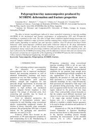
Fig. 14 shows the number <strong>of</strong> stress cycles<br />
N p required for a crack to propagate from the<br />
<strong>in</strong>itial (a th) to the critical (a c) crack length for<br />
gear rim thickness s R = 3.3×h, where two load<strong>in</strong>g<br />
conditions are taken <strong>in</strong>to account: (i) normal<br />
pulsat<strong>in</strong>g force act<strong>in</strong>g at the highest po<strong>in</strong>t <strong>of</strong> the<br />
583
Strojniški vestnik - Journal <strong>of</strong> Mechanical Eng<strong>in</strong>eer<strong>in</strong>g 57(2011)7-8, 579-586<br />
s<strong>in</strong>gle tooth contact (HPSTC), and (ii) the load<br />
moves along the tooth flank. It is clear that the<br />
crack grows faster <strong>in</strong> the case <strong>of</strong> mov<strong>in</strong>g load<strong>in</strong>g<br />
conditions. Similar results for gear rim thickness<br />
s R = 0.3×h are shown <strong>in</strong> Fig. 15.<br />
Fig. 11. The diagram (K eq ‒ a) for mov<strong>in</strong>g contact<br />
load<strong>in</strong>g<br />
Fig. 12. The FEM-mesh and crack path for gear<br />
rim thickness s R = 3.3×h for mov<strong>in</strong>g contact<br />
load<strong>in</strong>g<br />
Fig. 13. The FEM-mesh and crack path for gear<br />
rim thickness s R = 0.3×h for mov<strong>in</strong>g contact<br />
load<strong>in</strong>g<br />
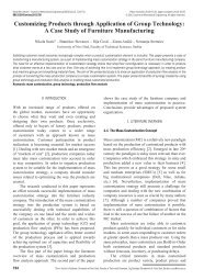
Fig. 16 shows the crack paths which have<br />
been determ<strong>in</strong>ed numerically for different rim<br />
thicknesses and different load<strong>in</strong>g conditions.<br />
The numerical determ<strong>in</strong>ed crack paths are then<br />
compared with the experimental results taken from<br />
[7]. A reasonable agreement between numerical<br />
and experimental results for deeper rim thickness<br />
is observed. This is not the case for th<strong>in</strong>ner rim<br />
thickness where the numerical determ<strong>in</strong>ed crack<br />
path significantly differs from the experimental<br />
results especially for larger crack lengths.<br />
584 Podrug, S. ‒ Glodež, S. ‒ Jelaska, D.<br />
Fig. 14. <strong>Crack</strong> propagation live for s R = 3.3×h<br />
Fig. 15. <strong>Crack</strong> propagation live for s R = 0.3×h<br />
Fig. 16. <strong>Crack</strong> paths for; a) sR = 3.3×h,<br />
b) sR=0.3×h (A = numerical for HPSTC load<strong>in</strong>g,<br />
B = numerical for mov<strong>in</strong>g load<strong>in</strong>g, C = experimental)<br />
5 CONCLUSIONS<br />
The numerical model used to predict<br />
the fatigue crack growth <strong>in</strong> a gear tooth root is
Strojniški vestnik - Journal <strong>of</strong> Mechanical Eng<strong>in</strong>eer<strong>in</strong>g 57(2011)7-8, 579-586<br />
presented <strong>in</strong> this paper. The fact that <strong>in</strong> an actual<br />
gear operation the magnitude as well as the<br />
position <strong>of</strong> the force change as the gear rotates<br />
through the mesh, is taken <strong>in</strong>to account. In such a<br />
way, a more realistic stress cycle <strong>in</strong> gear tooth root<br />
is obta<strong>in</strong>ed. The effect <strong>of</strong> gear rim thickness on the<br />
fatigue crack propagation <strong>in</strong> a gear tooth root and<br />
formation <strong>of</strong> a crack path is also studied. In the<br />
numerical computations the crack closure effect<br />
is also taken <strong>in</strong>to account, extend<strong>in</strong>g an analytical<br />
model for plasticity <strong>in</strong>duced crack closure with<br />
the partial crack closure concept. In this way, two<br />
other closure mechanisms: roughness and oxide<br />
<strong>in</strong>duced crack closure are not considered.<br />
Us<strong>in</strong>g the numerical procedure described<br />
above the predictions <strong>of</strong> crack propagation lives<br />
and crack paths <strong>in</strong> regard to the gear tooth root<br />
stresses are obta<strong>in</strong>ed. They are significantly<br />
different <strong>in</strong> comparison to some simplified<br />
models, which have been published previously.<br />
6 REFERENCES<br />
[1] ISO 6336 (2006). Calculation <strong>of</strong> load capacity<br />
<strong>of</strong> spur and helical gears, International<br />
Standard, Geneve.<br />
[2] Glodež, S., Šraml, M., Kramberger, J. (2002).<br />
A computational model for determ<strong>in</strong>ation <strong>of</strong><br />
service life <strong>of</strong> gears. International Journal <strong>of</strong><br />
Fatigue, vol. 24, p. 1013-1020.<br />
[3] Podrug, S., Jelaska D., Glodež, S. (2008).<br />
Influence <strong>of</strong> different load models on gear<br />
crack path shapes and fatigue lives. Fatigue<br />
and Fracture <strong>of</strong> Eng<strong>in</strong>eer<strong>in</strong>g Materials and<br />
Structures, vol. 31, p. 327-339.<br />
[4] Pehan, S., Hellen, T.K., Flašker, J., Glodež, S.<br />
(1997). <strong>Numerical</strong> methods for determ<strong>in</strong><strong>in</strong>g<br />
stress <strong>in</strong>tensity factors vs crack depth <strong>in</strong> gear<br />
tooth root. International Journal <strong>of</strong> Fatigue,<br />
vol. 19, p. 677-685.<br />
[5] Blaras<strong>in</strong>, A., Guagliano, M., Vergani, L.<br />
(1997). Fatigue crack growth prediction <strong>in</strong><br />
specimens similar to spur gear teeth. Fatigue<br />
and Fracture <strong>of</strong> Eng<strong>in</strong>eer<strong>in</strong>g Materials and<br />
Structures, vol. 20, p. 1171-1182.<br />
[6] Kato, M., Deng, G., Inoue, K., Takatsu,<br />
N. (1993). Evaluation <strong>of</strong> the strength <strong>of</strong><br />
carburized spur gear teeth based on fracture<br />
mechanics. JSME International Journal, vol.<br />
36, p. 233-240.<br />
<strong>Numerical</strong> <strong>Modell<strong>in</strong>g</strong> <strong>of</strong> <strong>Crack</strong> <strong>Growth</strong> <strong>in</strong> a <strong>Gear</strong> <strong>Tooth</strong> <strong>Root</strong><br />
[7] Lewicki, D.G., Ballar<strong>in</strong>i, R. (1997). Rim<br />
thickness effects on gear crack propagation<br />
life. International Journal <strong>of</strong> Fatigue, vol. 87,<br />
p. 59-86.<br />
[8] Spievak, L.E., Wawrzynek, P.A., Ingraffea,<br />
A.R., Lewicki, D.G. (2001). Simulat<strong>in</strong>g<br />
fatigue crack growth <strong>in</strong> spiral bevel gears.<br />
Eng<strong>in</strong>eer<strong>in</strong>g Fracture Mechanics, vol. 68, p.<br />
53-76.<br />
[9] Kitagawa, H., Takahashi, S. (1976).<br />
Applicability <strong>of</strong> fracture mechanics to<br />
very small cracks or cracks <strong>in</strong> the early<br />
stage. Proceed<strong>in</strong>gs <strong>of</strong> the 2 nd International<br />
Conference on the Behaviour <strong>of</strong> Materials, p.<br />
627-631.<br />
[10] Bhattacharya, B., Ell<strong>in</strong>gwood B. (1998).<br />
Cont<strong>in</strong>uum damage mechanics analysis <strong>of</strong><br />
fatigue crack <strong>in</strong>itiation. International Journal<br />
<strong>of</strong> Fatigue, vol. 20, p. 631-639.<br />
[11] Ewalds, H.L., Wanhill, R.J. (1989). Fracture<br />
Mechanics. Edward Arnold Publication,<br />
London.<br />
[12] ASTM E 399-80, American standard, West<br />
Conshohocken.<br />
[13] FRANC2D (2000). User’s Guide, Version<br />
2.7. Cornell University, Ithaca<br />
[14] Shih, C.F., de Lorenzi, H.G., German, M.D.<br />
(1976). <strong>Crack</strong> extension modell<strong>in</strong>g with<br />
s<strong>in</strong>gular quadratic isoparametric elements.<br />
International Journal <strong>of</strong> Fracture, vol. 12, p.<br />
647-651.<br />
[15] Narayana, K., Dattaguru, B. (1996). Certa<strong>in</strong><br />
aspects related to computation by modified<br />
crack closure <strong>in</strong>tegral (MCCI). Eng<strong>in</strong>eer<strong>in</strong>g<br />
Fracture Mechanics, vol. 55, p. 335-339.<br />
[16] Raju, I.S., Shivakumar, K.N. (1990). An<br />
equivalent doma<strong>in</strong> <strong>in</strong>tegral method <strong>in</strong> the twodimensional<br />
analysis <strong>of</strong> mixed mode crack<br />
problems. Eng<strong>in</strong>eer<strong>in</strong>g Fracture Mechanics,<br />
vol. 37, p. 707-725.<br />
[17] Bittencourt, T.N., Wawrzynek, P.A.,<br />
Ingraffea, A.R., Sousa, J.L. (1996). Quasiautomatic<br />
simulation <strong>of</strong> crack propagation for<br />
2D LEFM problems. Eng<strong>in</strong>eer<strong>in</strong>g Fracture<br />
Mechanics, vol. 55, p. 321-334.<br />
[18] Erdogan, F., Sih, G.C. (1963). On the crack<br />
extension <strong>in</strong> plates under plane load<strong>in</strong>g<br />
and transverse shear. Journal <strong>of</strong> Basic<br />
Eng<strong>in</strong>eer<strong>in</strong>g D, vol. 85, p. 519-525.<br />
585
Strojniški vestnik - Journal <strong>of</strong> Mechanical Eng<strong>in</strong>eer<strong>in</strong>g 57(2011)7-8, 579-586<br />
[19] Sih, G.C. (1974). Stra<strong>in</strong> energy density factor<br />
applied to mixed mode crack problems.<br />
International Journal <strong>of</strong> Fracture, vol. 10, p.<br />
305-321.<br />
[20] Hussa<strong>in</strong>, M.A., Pu, S.L., Underwood, J.<br />
(1974). Stra<strong>in</strong> energy release rate for a crack<br />
under comb<strong>in</strong>ed mode I and mode II. Fract<br />
Anal ASTM STP. vol. 560, p. 2-28.<br />
[21] Yan, X., Du, S., Zhang, Z. (1992). Mixedmode<br />
fatigue crack growth prediction <strong>in</strong><br />
biaxially streched sheets. Eng<strong>in</strong>eer<strong>in</strong>g<br />
Fracture Mechanics, vol. 43, p. 471-475.<br />
586 Podrug, S. ‒ Glodež, S. ‒ Jelaska, D.<br />
[22] Abdel Mageed, A.M., Pandey, R.K. (1992).<br />
Studies on cyclic crack path and the mixedmode<br />
crack closure behaviour <strong>in</strong> Al alloy.<br />
International Journal <strong>of</strong> Fatigue, vol. 14, p.<br />
21-29.<br />
[23] Budiansky, B., Hutch<strong>in</strong>son, J.W. (1978).<br />
Analysis <strong>of</strong> closure <strong>in</strong> fatigue crack growth.<br />
Journal <strong>of</strong> Applied Mechanics, vol. 45, p.<br />
267-276.<br />
[24] Kujawski, D. (2001). Enhanced model <strong>of</strong><br />
partial crack closure for correlation <strong>of</strong> R –<br />
ratio effects <strong>in</strong> alum<strong>in</strong>um alloys. International<br />
Journal <strong>of</strong> Fatigue, vol. 23, p. 95-102.