Calculation of the Combined Torsional Mesh Stiffness of Spur Gears ...
Calculation of the Combined Torsional Mesh Stiffness of Spur Gears ...
Calculation of the Combined Torsional Mesh Stiffness of Spur Gears ...

You also want an ePaper? Increase the reach of your titles
YUMPU automatically turns print PDFs into web optimized ePapers that Google loves.
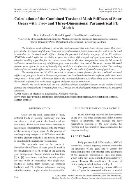
Strojniški vestnik - Journal <strong>of</strong> Mechanical Engineering 57(2011)11, 810-818 Paper received: 07.12.2010DOI: 10.5545/sv-jme.2010.248 Paper accepted: 02.08.2011<strong>Calculation</strong> <strong>of</strong> <strong>the</strong> <strong>Combined</strong> <strong>Torsional</strong> <strong>Mesh</strong> <strong>Stiffness</strong> <strong>of</strong> <strong>Spur</strong><strong>Gears</strong> with Two- and Three-Dimensional Parametrical FEModelsKiekbusch, T. ‒ Sappok, D. ‒ Sauer, B. ‒ Howard, I.Timo Kiekbusch 1,* ‒ Daniel Sappok 1 ‒ Bernd Sauer 1 ‒ Ian Howard 21 University <strong>of</strong> Kaiserslautern, Institute for Machine Elements, <strong>Gears</strong> and Transmissions, Germany2 Curtin University Perth, Department <strong>of</strong> Mechanical Engineering, AustraliaThe torsional mesh stiffness is one <strong>of</strong> <strong>the</strong> most important characteristics <strong>of</strong> spur gears. This paperpresents <strong>the</strong> development <strong>of</strong> detailed two- and three-dimensional finite element models which can be usedto calculate <strong>the</strong> torsional mesh stiffness. Using <strong>the</strong> parametrical design language <strong>of</strong> <strong>the</strong> FE s<strong>of</strong>twareANSYS <strong>the</strong> models <strong>of</strong>fer <strong>the</strong> possibility to generate various different pairs <strong>of</strong> spur gears and include anadaptive meshing algorithm for <strong>the</strong> contact zones. Due to <strong>the</strong> short computation times <strong>the</strong> 2D model iswell suited to simulate a variety <strong>of</strong> different gear pairs in a short time period. The more complex 3D modelfeatures more options in terms <strong>of</strong> investigating tooth face modifications for fur<strong>the</strong>r studies. The resultingvalues <strong>of</strong> <strong>the</strong> torsional stiffness can be used – for example – in multi body simulations <strong>of</strong> gearboxes.The results from <strong>the</strong> 2D FEA are used to derive a simple formula for <strong>the</strong> combined torsionalstiffness <strong>of</strong> spur gears in mesh. The results presented are based on <strong>the</strong> individual stiffness <strong>of</strong> <strong>the</strong> three maincomponents – body, teeth and contact. Hence, <strong>the</strong> introduced formula uses <strong>the</strong>se three parts to determine<strong>the</strong> overall stiffness for a wide range <strong>of</strong> gears and gear ratio combinations.Finally, <strong>the</strong> results from both <strong>the</strong> two- and three-dimensional finite element model and <strong>the</strong> derivedformula are compared and <strong>the</strong> results from <strong>the</strong> 3D model are checked against results obtained by analyticalequations.©2011 Journal <strong>of</strong> Mechanical Engineering. All rights reserved.Keywords: gear dynamic modelling, spur gear, finite element modelling, torsional mesh stiffness,contact stiffness0 INTRODUCTION<strong>Gears</strong> are <strong>the</strong> main component <strong>of</strong> manydifferent kinds <strong>of</strong> rotating machinery and <strong>the</strong>yare <strong>of</strong>ten a critical part to <strong>the</strong> function <strong>of</strong> <strong>the</strong>machinery. There have been many attempts inrecent years to understand and describe <strong>the</strong> process<strong>of</strong> <strong>the</strong> meshing <strong>of</strong> spur gears. As <strong>the</strong> process <strong>of</strong>meshing is very complex and difficult to describe,<strong>the</strong> finite element analysis is <strong>the</strong> method <strong>of</strong> choiceto investigate <strong>the</strong> underlying relationships.The approach used in this paper todetermine <strong>the</strong> stiffness <strong>of</strong> spurs gears in mesh is<strong>the</strong> development <strong>of</strong> a FE model <strong>of</strong> <strong>the</strong> completegear arrangement. Recent studies on this topic[1] to [4] have shown that <strong>the</strong>se models produce<strong>the</strong> best results in comparison with single-toothmodels or partial teeth models. As computerhardware and FE s<strong>of</strong>tware advances, workingwith <strong>the</strong>se ra<strong>the</strong>r complex models is now feasible.1 THE FINITE ELEMENT GEAR MODELSIn <strong>the</strong> following sections <strong>the</strong> development<strong>of</strong> <strong>the</strong> two- and three-dimensional finite elementmodels is described. This involves <strong>the</strong> fullyparametrical creation <strong>of</strong> <strong>the</strong> gear shape, <strong>the</strong>meshing and <strong>the</strong> simulation process including <strong>the</strong>adaptive meshing.1.1 2D FE ModelFully parametrical APDL-scripts (ANSYSParametric Design Language) are used to describe<strong>the</strong> geometry <strong>of</strong> <strong>the</strong> gears and to control <strong>the</strong>simulation process. The first step is <strong>the</strong> generation<strong>of</strong> <strong>the</strong> geometry consisting <strong>of</strong> lines and areas,which in <strong>the</strong> next step are meshed with a relativelycoarse FE-mesh. The result is a FE model <strong>of</strong>pinion and gear which is shown in Fig. 1.The process <strong>of</strong> creating various differentpairs <strong>of</strong> gears is automated with <strong>the</strong> powerful810*Corr. Author’s Address: Institute for Machine Elements, <strong>Gears</strong> and Transmissons,Gottlieb-Daimler-Str., 67663 Kaiserslautern, Germany, timo.kiekbusch@mv.uni-kl.de
Strojniški vestnik - Journal <strong>of</strong> Mechanical Engineering 57(2011)11, 810-818design language <strong>of</strong> ANSYS. Without changing<strong>the</strong> model itself many parameters like modulus,number <strong>of</strong> teeth, shaft radius etc. can easilybe varied as all parameters are provided in adata input file. This file is loaded during <strong>the</strong>preprocessing.different angular positions <strong>of</strong> <strong>the</strong> gears. Therefore,<strong>the</strong> gears have to be rotated to <strong>the</strong> correspondingposition before <strong>the</strong> model is solved. At everyroll angle <strong>the</strong> contact point(s) change so that <strong>the</strong>mesh refinement at <strong>the</strong> contact point(s) requirean adaptive remesh algorithm which takes intoaccount <strong>the</strong> actual contact situation.Fig. 1. Result from <strong>the</strong> first APDL-script; premeshedgeometryAs <strong>the</strong> contact between pinion and gear is<strong>the</strong> most important and critical part <strong>of</strong> <strong>the</strong> gearsimulation <strong>the</strong> description <strong>of</strong> <strong>the</strong> tooth involutesand feet require <strong>the</strong> highest possible precisionduring <strong>the</strong> modelling process. Therefore, bothgeometric details are generated by using a veryhigh number <strong>of</strong> keypoints. The location <strong>of</strong> <strong>the</strong>sepoints is calculated on <strong>the</strong> basis <strong>of</strong> <strong>the</strong> data inputfile. The keypoints are connected with splinesto represent <strong>the</strong> outline <strong>of</strong> <strong>the</strong> tooth geometry.After adding <strong>the</strong> gear body <strong>the</strong> areas created aremeshed with a coarse mesh. This model (see Fig.1) is <strong>the</strong> basis for <strong>the</strong> next steps <strong>of</strong> <strong>the</strong> modellingprocess namely <strong>the</strong> mesh refinement at <strong>the</strong> contactpoint(s). This refinement is realised using ano<strong>the</strong>rAPDL-Script. The result is shown in Fig. 2. Thisscript also adds <strong>the</strong> constraints, contact elementsand different torque loads to <strong>the</strong> model, solvesand post processes <strong>the</strong> job. The constraints usedin <strong>the</strong> model are as follows: <strong>the</strong> hub <strong>of</strong> <strong>the</strong> gear iscompletely constrained from motion; <strong>the</strong> nodes at<strong>the</strong> hub <strong>of</strong> <strong>the</strong> pinion can only rotate around <strong>the</strong>centre <strong>of</strong> <strong>the</strong> pinion. The torque is applied usinga force on every node at <strong>the</strong> driving gear’s hub,adding up to <strong>the</strong> specified torque.A quasi-static simulation method is usedfor <strong>the</strong> determination <strong>of</strong> <strong>the</strong> mesh stiffness. Thismeans that <strong>the</strong> stiffness is calculated at severala) b)Fig. 2. Adaptive refining <strong>of</strong> <strong>the</strong> mesh at <strong>the</strong>contact point(s); a) remeshed contact for singlecontact, b) remeshed contact for double contactDuring <strong>the</strong> automated postprocessing <strong>the</strong>following results are extracted from <strong>the</strong> model:combined torsional mesh stiffness, deformation <strong>of</strong>gear body, teeth and contact zone for both pinionand gear. This data is written to a text file forfur<strong>the</strong>r processing.When analysing gears with tooth shapeerrors or pr<strong>of</strong>ile correction, an initial gapbetween <strong>the</strong> teeth can occur. In order to createa very flexible model which can be used infur<strong>the</strong>r studies, <strong>the</strong> model was built to be able tosolve problems including an initial gap betweenmeshing teeth. Typically a static FE model cannotbe solved if some parts <strong>of</strong> <strong>the</strong> model do not haveenough constraints as <strong>the</strong> stiffness matrix becomessingular [5]. This can happen, for example, ifa contact is not initially closed and in this case<strong>the</strong> pinion can rotate a small angle without anyresistance or stiffness.To avoid rigid body motion, a weak springis attached to <strong>the</strong> pinion. This small stiffnessprevents <strong>the</strong> unintentional rotational motion. Thisspring is only used for <strong>the</strong> initial simulation stepwith a very small torque just to get <strong>the</strong> teeth incontact. When <strong>the</strong> actual load torque is applied,<strong>the</strong> spring is disabled using <strong>the</strong> birth/death <strong>of</strong>elements command [6]. This approach can handlemuch bigger gaps (rigid body motion) than <strong>the</strong><strong>Calculation</strong> <strong>of</strong> <strong>the</strong> <strong>Combined</strong> <strong>Torsional</strong> <strong>Mesh</strong> <strong>Stiffness</strong> <strong>of</strong> <strong>Spur</strong> <strong>Gears</strong> with Two- and Three-DimensionalParametrical FE Models811
Strojniški vestnik - Journal <strong>of</strong> Mechanical Engineering 57(2011)11, 810-818automatic adjustment which tends to be used bydefault.1.2 3D FE ModelThere are some restrictions when usinga two dimensional FE model for <strong>the</strong> analysis <strong>of</strong>spur gears in mesh. For example, simulatinghelical gears or applying tooth face modificationsin <strong>the</strong> direction <strong>of</strong> <strong>the</strong> rotation axis <strong>of</strong> <strong>the</strong> gearlike crowning or face angle correction is notpossible. By using a three dimensional FE model<strong>the</strong>se restrictions can be evaded. Fur<strong>the</strong>rmore, <strong>the</strong>influence <strong>of</strong> misalignment between <strong>the</strong> rotationaxes <strong>of</strong> <strong>the</strong> gears as well as shaft centre distancechanges on <strong>the</strong> mesh stiffness can be investigated.The disadvantages <strong>of</strong> a three dimensional versusa two dimensional model are higher complexityand hardware requirements as well as computationtimes.In order to overcome <strong>the</strong> restrictions thatare given by <strong>the</strong> 2D model a three dimensional FEmodel built on <strong>the</strong> latter was developed. Again afully parametrical approach was used to create <strong>the</strong>shape <strong>of</strong> <strong>the</strong> gears and an initial coarse mesh. Inaddition <strong>the</strong> model was designed to support <strong>the</strong>modelling <strong>of</strong> helical gears and <strong>the</strong> application <strong>of</strong>tooth face modifications for fur<strong>the</strong>r studies.To create <strong>the</strong> gear model, each gear wheelis sliced into multiple layers along <strong>the</strong> rotationaxis. For each layer, <strong>the</strong> two dimensional shape<strong>of</strong> <strong>the</strong> gear is modelled by keypoints which areconnected with straights, arcs and splines. Thetooth involutes and roots are described with ahigh number <strong>of</strong> keypoints to provide a very highaccuracy like in <strong>the</strong> 2D model. As each 2D shape<strong>of</strong> <strong>the</strong> gear is built separately, <strong>the</strong> tooth shape canbe changed along <strong>the</strong> rotation axis. This procedureis a prerequisite to model helical gears and to apply<strong>the</strong> above mentioned tooth face modifications.Only <strong>the</strong> teeth which are involved inone mesh cycle are created for each gear. Thesurrounding teeth have only a subsidiary influenceon <strong>the</strong> mesh stiffness but demand a higher amount<strong>of</strong> elements which leads to higher computationtimes and hardware requirements. The gear bodiesare completely modelled.During <strong>the</strong> modelling process <strong>the</strong> gearsare completely meshed using a mapped meshingwith hexahedral elements. In this stage, <strong>the</strong> meshin <strong>the</strong> area <strong>of</strong> contact, that is on <strong>the</strong> tooth faceson <strong>the</strong> loaded side <strong>of</strong> <strong>the</strong> teeth, is comparativelycoarse. <strong>Mesh</strong> transitions between <strong>the</strong> body areasadjacent to modelled teeth and <strong>the</strong> rest <strong>of</strong> <strong>the</strong> gearbody are used to reduce <strong>the</strong> amount <strong>of</strong> elements.A completely meshed gear pair is shown inFig. 3.Fig. 3. <strong>Mesh</strong>ed gear pair created during <strong>the</strong>model build processA relatively fine mesh is needed toaccurately simulate <strong>the</strong> non-linear contactdeformation between <strong>the</strong> tooth faces. Thereare two options to refine <strong>the</strong> mesh in <strong>the</strong> area<strong>of</strong> contact during <strong>the</strong> simulation process. Thefirst one is to adaptively refine <strong>the</strong> mesh at <strong>the</strong>position(s) were <strong>the</strong> tooth face contact(s) occurs.The second one is to refine <strong>the</strong> complete toothfaces on <strong>the</strong> loaded side <strong>of</strong> <strong>the</strong> teeth. Fig. 4 shows<strong>the</strong> mesh refinement for two meshing angles with<strong>the</strong> first option.The modelling process generates a modeldatabase file and a parameter file which comprisesall necessary parameters. These files are used byan APDL-script in which <strong>the</strong> boundary conditionsand <strong>the</strong> contact elements are created, <strong>the</strong> solvingprocess is started and finally a fully automatedpostprocessing is conducted.In order to close an initial gap between<strong>the</strong> tooth faces and avoid rigid body motion, <strong>the</strong>usage <strong>of</strong> a small stiffness spring attached to <strong>the</strong>driving gear’s hub is adopted from <strong>the</strong> 2D model.This procedure is extended with a method tocompute <strong>the</strong> spring stiffness and <strong>the</strong> initial torqueload according to <strong>the</strong> actual gap size. Thereby <strong>the</strong>amount <strong>of</strong> simulation steps to close <strong>the</strong> initial gapcan be reduced to a minimum which consequentlyreduces <strong>the</strong> simulation time.During <strong>the</strong> postprocessing <strong>the</strong> sameresults as within <strong>the</strong> 2D model are extracted.812 Kiekbusch, T. ‒ Sappok, D. ‒ Sauer, B. ‒ Howard, I.
Strojniški vestnik - Journal <strong>of</strong> Mechanical Engineering 57(2011)11, 810-818a) b)Fig. 4. Adaptive refining <strong>of</strong> <strong>the</strong> mesh at <strong>the</strong> contact point(s) for <strong>the</strong> 3D model; a) remeshed contact forsingle contact, b) remeshed contact for double contactThat is <strong>the</strong> combined torsional mesh stiffness, <strong>the</strong>deformation <strong>of</strong> gear body, teeth and contact zonefor pinion and gear.2 THE COMBINED TORSIONAL MESHSTIFFNESSThe definition <strong>of</strong> <strong>the</strong> combined torsionalmesh stiffness K m used in this paper is <strong>the</strong> quotient<strong>of</strong> input load T [Nm] and driving gear hub rotationunder load T.E. [rad] [6] to [8]:TKm = TE . . . (1)This definition can be used for <strong>the</strong> dynamicsimulation <strong>of</strong> spur gear systems as it directlydescribes <strong>the</strong> relation between load torque andrelative motion <strong>of</strong> <strong>the</strong> gears.In 2001, Jia [2] introduced a commonformula describing <strong>the</strong> combined torsional meshstiffness by body and tooth bending stiffness. Thissimplification neglects <strong>the</strong> effect <strong>of</strong> <strong>the</strong> appliedtorque on <strong>the</strong> gearing's stiffness. The results from<strong>the</strong> FE model, however, show that <strong>the</strong>re is aninfluence <strong>of</strong> <strong>the</strong> torque on <strong>the</strong> resulting combinedtorsional mesh stiffness as shown in Fig. 5.The studies <strong>of</strong> <strong>the</strong> deformational behaviour<strong>of</strong> <strong>the</strong> gear wheels show that <strong>the</strong> stiffness <strong>of</strong> gearbody and teeth are almost load-independent while<strong>the</strong> contact deformation is non-linear, as a Hertziancontact occurs between <strong>the</strong> teeth <strong>of</strong> <strong>the</strong> gears. Theinfluence <strong>of</strong> <strong>the</strong> applied torque on <strong>the</strong> component’sstiffness is shown in Fig. 6. The position and width<strong>of</strong> <strong>the</strong> handover region between single and doublecontact zone are also torque-dependent which hasalso been shown previously [1].Fig. 5. <strong>Torsional</strong> mesh stiffness for a complete mesh cycle with different torque loads (model with 1:1 gearratio, 23 teeth, modulus 6 mm, steel)<strong>Calculation</strong> <strong>of</strong> <strong>the</strong> <strong>Combined</strong> <strong>Torsional</strong> <strong>Mesh</strong> <strong>Stiffness</strong> <strong>of</strong> <strong>Spur</strong> <strong>Gears</strong> with Two- and Three-DimensionalParametrical FE Models813
Strojniški vestnik - Journal <strong>of</strong> Mechanical Engineering 57(2011)11, 810-818Fig. 6. Influence <strong>of</strong> <strong>the</strong> applied torque on body, teeth and contact stiffness (model with 1:1 gear ratio, 23teeth, modulus 6 mm, steel)3 TORSIONAL STIFFNESS OF A SINGLEGEARThe description <strong>of</strong> <strong>the</strong> torsional meshstiffness is based on <strong>the</strong> assumption that <strong>the</strong>stiffness <strong>of</strong> body, teeth and contact zone can beconsidered to act like three springs in a row, whichmeans that <strong>the</strong> combined stiffness K i [Nm/rad] foreach pinion and gear can be calculated as:( )−1−1 −1 −1i B, i T, i C, i ,K = K + K + K(2)where K B,i is <strong>the</strong> gear body stiffness, K T,i <strong>the</strong> toothstiffness and K C,i <strong>the</strong> contact stiffness with i beingP or G for pinion resp. gear.Fig. 7. Nodes selected to determine <strong>the</strong>component’s deformationIt has to be mentioned that <strong>the</strong>se valuesare not <strong>the</strong> actual stiffness values <strong>of</strong> <strong>the</strong> particularcomponent, but items which help to develop <strong>the</strong>common formula for <strong>the</strong> mesh stiffness. In <strong>the</strong>following pages <strong>the</strong> combined gear stiffness K iis used to calculate <strong>the</strong> stiffness for <strong>the</strong> two gearsin mesh. The values <strong>of</strong> K B,i , K T,i and K C,i can beobtained from <strong>the</strong> FE model. For this purpose<strong>the</strong> deformations <strong>of</strong> body, teeth and contact zonehave to be separated. In <strong>the</strong> FE model differentnodes are used to read out <strong>the</strong>ir displacements.These displacements are put into relation with <strong>the</strong>applied torque which results in <strong>the</strong> component’sstiffness. The nodes which are chosen to receive<strong>the</strong> deformation data are placed at <strong>the</strong> shaft radius,<strong>the</strong> dedendum radius and at <strong>the</strong> radius <strong>of</strong> contact;in each case in <strong>the</strong> middle <strong>of</strong> <strong>the</strong> tooth in contactand in addition one node at <strong>the</strong> contact point. Fig.7 shows <strong>the</strong> placement <strong>of</strong> <strong>the</strong> selected nodes for asingle tooth pair in contact.3.1 <strong>Stiffness</strong> for <strong>the</strong> Driving Gear with a SinglePair <strong>of</strong> Teeth in ContactThe description <strong>of</strong> <strong>the</strong> torsional stiffness<strong>of</strong> <strong>the</strong> different components requires an analysiswhich gearing parameters affect <strong>the</strong> particularstiffness. The relevant parameters for eachcomponent are pointed out in <strong>the</strong> correspondingsections.The range <strong>of</strong> <strong>the</strong> gear model parameterswhich have been used for this research is shownin Table 1.Table 1. Range <strong>of</strong> parameters for <strong>the</strong> models usedin this researchParameter Unit Min MaxNumber <strong>of</strong> teeth z [-] 7 50Modulus m [mm] 3 15Torque load T [Nm] 0.1 1000Gear ratio u [-] 0.34 2.94814 Kiekbusch, T. ‒ Sappok, D. ‒ Sauer, B. ‒ Howard, I.
Strojniški vestnik - Journal <strong>of</strong> Mechanical Engineering 57(2011)11, 810-8183.1.1 <strong>Stiffness</strong> <strong>of</strong> <strong>the</strong> Gear BodyThe stiffness <strong>of</strong> <strong>the</strong> gear body is assumedto only depend on <strong>the</strong> following parameters: shaftradius r s dedendum radius r d , face width w andYoung’s modulus E.A simplified model (see Fig. 8) is usedto analyse <strong>the</strong> influence <strong>of</strong> <strong>the</strong> above mentionedparameters on <strong>the</strong> body’s stiffness. Differentcombinations <strong>of</strong> parameters were used to come to<strong>the</strong> following Eq.:( ) ⋅16 . 16 .BP , B d s sK = c ⋅E⋅w⋅ln r − r r ,(3)where c B is a coefficient which was found out tobe 9.555e -4 .The results from this equation reproduce<strong>the</strong> results from <strong>the</strong> FE model within an accuracy<strong>of</strong> about 5% for gear bodies with a outer radiusbetween 10 and 200 mm and various inner radii.where c T is a coefficient which was found out tobe 3.2e -5 . The results from this Eq. are within 7%<strong>of</strong> <strong>the</strong> results from <strong>the</strong> FE model for <strong>the</strong> parameterrange analysed.3.1.3 <strong>Stiffness</strong> <strong>of</strong> <strong>the</strong> Teeth ContactIn contrast to <strong>the</strong> stiffness mentionedabove, <strong>the</strong> stiffness <strong>of</strong> <strong>the</strong> contact between <strong>the</strong>meshing teeth is highly non-linear with <strong>the</strong> loadas it is a Hertzian contact between two curvedsurfaces. Therefore, <strong>the</strong> load torque T needs to beconsidered in <strong>the</strong> equation describing <strong>the</strong> contactstiffness. In addition, <strong>the</strong> following parametershave been found out to have a significantinfluence: modulus m and number <strong>of</strong> teeth z,contact radius, Young’s modulus E and face widthw. The contact stiffness is approximated by:K = c ⋅E⋅w⋅m ⋅z ⋅TCP ,C185 . 2 0.105,(5)where <strong>the</strong> coefficient c C is 7.937e -5 . The resultsfor <strong>the</strong> contact stiffness were found to be within10% <strong>of</strong> <strong>the</strong> results from <strong>the</strong> FE model.3.2 <strong>Stiffness</strong> for <strong>the</strong> Driven Gear with a SinglePair <strong>of</strong> Teeth in ContactFig. 8. Simplified model <strong>of</strong> <strong>the</strong> gear body withapplied constraints and forces3.1.2 Bending <strong>Stiffness</strong> <strong>of</strong> <strong>the</strong> TeethAs <strong>the</strong> teeth basically bend under load,<strong>the</strong> assumption is made that <strong>the</strong> parameters thatinfluence <strong>the</strong> stiffness <strong>of</strong> <strong>the</strong> teeth are <strong>the</strong> sameas those <strong>of</strong> a bending beam. These parametersare: height and width w <strong>of</strong> <strong>the</strong> teeth and Young’smodulus E. The influence <strong>of</strong> <strong>the</strong> radius at which<strong>the</strong> tooth is located and <strong>the</strong> tooth height was takeninto account with <strong>the</strong> parameters modulus m andnumber <strong>of</strong> teeth z. This results in <strong>the</strong> stiffness <strong>of</strong><strong>the</strong> tooth K T,P :K = c ⋅E⋅w⋅m ⋅ zTP ,T2 22 .,(4)The stiffness values determined aboveare related to <strong>the</strong> driving gear (index P). With<strong>the</strong> given gear ratio u, <strong>the</strong> driven gear’s stiffness(index G) can be directly deduced taking intoaccount that both load torque and radius <strong>of</strong> contactare u-times <strong>the</strong> respective torque and contactradius <strong>of</strong> <strong>the</strong> driving gear. So <strong>the</strong> body, teeth andcontact stiffnesses are calculated by:2 zPKiG , = KiP , ⋅ u = KiP, ⋅ ⎛ ,⎝ ⎜ ⎞⎟ (6)zG⎠with i being <strong>the</strong> indices B, T and C for body,teeth and contact. It has to be mentioned that <strong>the</strong>parameters <strong>of</strong> <strong>the</strong> driven gear have to be used for<strong>the</strong> calculation <strong>of</strong> its stiffness (e.g. z G , E G ).3.3 <strong>Stiffness</strong> in <strong>the</strong> Double Contact ZoneThe body’s stiffness value in <strong>the</strong> doublecontact zone is obtained by adding <strong>the</strong> factor f B .The only difference between single and doublecontact for <strong>the</strong> body stiffness is <strong>the</strong> width <strong>of</strong> <strong>the</strong>2<strong>Calculation</strong> <strong>of</strong> <strong>the</strong> <strong>Combined</strong> <strong>Torsional</strong> <strong>Mesh</strong> <strong>Stiffness</strong> <strong>of</strong> <strong>Spur</strong> <strong>Gears</strong> with Two- and Three-DimensionalParametrical FE Models815
Strojniški vestnik - Journal <strong>of</strong> Mechanical Engineering 57(2011)11, 810-818area which is affected by <strong>the</strong> load. This influenceThe results from <strong>the</strong> formula are withinneeds fur<strong>the</strong>r investigation which can be done−1 −1 −1K = K + K . (10) using <strong>the</strong> FE model.is considered to be ra<strong>the</strong>r small which wasconfirmed by <strong>the</strong> FE model. Hence, <strong>the</strong> factor f Bwas found to be equal to 1.1:10% from <strong>the</strong> 2D FE model’s results for mostinput parameter sets. This accuracy seems tobe good enough for most <strong>of</strong> <strong>the</strong> cases where <strong>the</strong>formula can be used as <strong>the</strong>re are many o<strong>the</strong>rKiB , , double = fB ⋅ Ki, B, single = 11 . ⋅Ki, B,single. , (7) different factors which influence <strong>the</strong> value <strong>of</strong> <strong>the</strong>mesh stiffness, like <strong>the</strong> shaft to collar connectionThe description <strong>of</strong> <strong>the</strong> double contact zone and <strong>the</strong> lubrication <strong>of</strong> <strong>the</strong> gears.teeth stiffness assumes that both teeth pairs share<strong>the</strong> load equally. This means that each tooth’sdeformation is half <strong>the</strong> deformation as in <strong>the</strong> singlecontact zone. This results in a stiffness value twiceas high as for <strong>the</strong> single contact:KiT, , double = 2 ⋅KiT, , single.(8) Fig. 9. Simplified model <strong>of</strong> <strong>the</strong> combined torsionalmesh stiffness <strong>of</strong> two gears in meshThe evaluation <strong>of</strong> <strong>the</strong> contact stiffnessshows that <strong>the</strong> difference between single andA simple modification during <strong>the</strong>double contact cannot only be described by asimple factor but by an additional change <strong>of</strong> <strong>the</strong>exponent for <strong>the</strong> applied load (cf. Eq. (5)):calculation can be made to take into account <strong>the</strong>small variation <strong>of</strong> <strong>the</strong> stiffness inside <strong>the</strong> singleor double contact zone. Adding a quadraticcorrection term will result in a lower difference. .KiC, , double = cCE w 185m 2z 0 068T , (9) between <strong>the</strong> simulated and <strong>the</strong> calculated valuesover <strong>the</strong> whole mesh cycle (see Fig. 10). Thewhere c C is 1.1905e -4 .modified stiffness K m * against <strong>the</strong> distance from<strong>the</strong> actual relative roll angle to <strong>the</strong> centre <strong>of</strong> <strong>the</strong>3.4 The Formula for <strong>the</strong> <strong>Combined</strong> <strong>Torsional</strong> single resp. double contact zone ΔΩ is:<strong>Mesh</strong> <strong>Stiffness</strong>2Km* = Km⋅( 1−c⋅∆© ), (11)The stiffness for <strong>the</strong> single gear (K P , K G )is calculated by assuming all three springs in arow as mentioned above. The combined torsionalmesh stiffness K m can be derived by considering<strong>the</strong> two gears as two springs in series (see Fig. 9):with <strong>the</strong> factor c which has to be adapted on basis<strong>of</strong> <strong>the</strong> FE model.The determination <strong>of</strong> <strong>the</strong> position andwidth <strong>of</strong> <strong>the</strong> hand-over region, however, still( )m P GFig. 10. Comparison <strong>of</strong> <strong>the</strong> FE results with quadratic correction term (Eq. (11))816 Kiekbusch, T. ‒ Sappok, D. ‒ Sauer, B. ‒ Howard, I.
Strojniški vestnik - Journal <strong>of</strong> Mechanical Engineering 57(2011)11, 810-8184 RESULTSDue to <strong>the</strong> fact that <strong>the</strong> FEA <strong>of</strong> a spur gearpair is complex and <strong>the</strong>refore prone to errors<strong>the</strong> results have to be checked for plausibility.Hence <strong>the</strong> results from <strong>the</strong> 2D and 3D model aswell as <strong>the</strong> mesh stiffness formula are comparedwith each o<strong>the</strong>r. Additionally, <strong>the</strong> results from <strong>the</strong>3D model are checked against analytical resultsaccording to DIN 3990 [9]. A variety <strong>of</strong> gear pairshas been used for this comparison. Table 2 showsan excerpt from <strong>the</strong> compared gear pairs.Table 2. Investigated gear pairs (excerpt)Variant-No. 1 2 3 4z 1 23 25 36 13z 2 23 25 43 31m [mm] 6 2 11 4α [°] 20 20 20 20w 1 [mm] 16 28 58 16w 2 [mm] 15 24 50 15R s1 [mm] 15 8 80 10R s2 [mm] 15 8 100 20E-Modulus [GPa] 210 210 210 2104.1 2D – 3D – <strong>Mesh</strong> <strong>Stiffness</strong> FormulaThe torsional mesh stiffness has beencalculated for <strong>the</strong> single contact zone (SCZ) and<strong>the</strong> double contact zone (DCZ) to check if <strong>the</strong> twoFE models and <strong>the</strong> mesh stiffness formula produceconsistent results.Table 3 shows <strong>the</strong> stiffness results and <strong>the</strong>proportion between FE and mesh stiffness formulafor each FE model.The results show a maximum deviation <strong>of</strong>10% that implies that <strong>the</strong> FEA and mesh stiffnessformula produce consistent results for <strong>the</strong> torsionalmesh stiffness.4.2 3D – DIN 3990DIN 3990 provides methods to calculate<strong>the</strong> load capacity <strong>of</strong> cylindrical gears whichincludes <strong>the</strong> determination <strong>of</strong> <strong>the</strong> tooth springstiffness. That is <strong>the</strong> normal tooth load which isneeded to deform a meshing tooth pair with 1 mmtooth width perpendicular to <strong>the</strong> tooth involute for1 mm. This deformation corresponds to <strong>the</strong> basecircle arc length and thus a rotation angle whichcan be converted into <strong>the</strong> before defined torsionalmesh stiffness. These results are compared toTable 3. Comparison <strong>of</strong> <strong>the</strong> torsional mesh stiffness (K m_MSF ) between 2D (K m_2D ), 3D FE simulation(K m_3D ) and <strong>the</strong> mesh stiffness formula (italic: proportion values)Variant-No. 1 2 3 4Torque Load [Nm] 1000 75 1000 100K m_MSF [10 6 Nm/rad] 0.562 1.00 0.152 1.00 22.8 1.00 0.100 1.00SCZ K m_2D [10 6 Nm/rad] 0.573 1.02 0.146 0.96 20.2 0.89 0.098 0.98K m_3D [10 6 Nm/rad] 0.594 1.06 0.154 1.01 22.1 0.97 0.102 1.02K m_MSF [10 6 Nm/rad] 0.722 1.00 0.206 1.00 31.4 1.00 0.138 1.00DCZ K m_2D [10 6 Nm/rad] 0.751 1.04 0.207 1.00 29.7 0.95 0.141 1.02K m_3D [10 6 Nm/rad] 0.781 1.08 0.215 1.04 30.9 0.98 0.145 1.05Table 4. Comparison <strong>of</strong> <strong>the</strong> torsional mesh stiffness between 3D FE simulation (K m_3D ) and DIN 3990(K m_DIN )Variant-No. 1 2 3 4Torque Load [Nm] 1000 75 1000 100Tooth Spring <strong>Stiffness</strong> [N/(mm∙μm)] 15.1 15.0 17.4 14.4Linear Distributed Load [N/mm] 966 125 101 256K m_3D [10 6 Nm/rad] 0.594 0.154 22.1 0.102SCZ K m_DIN [10 6 Nm/rad] 0.652 0.159 24.0 0.103K m_3D / K m_DIN 0.91 0.97 0.92 0.99<strong>Calculation</strong> <strong>of</strong> <strong>the</strong> <strong>Combined</strong> <strong>Torsional</strong> <strong>Mesh</strong> <strong>Stiffness</strong> <strong>of</strong> <strong>Spur</strong> <strong>Gears</strong> with Two- and Three-DimensionalParametrical FE Models817
Strojniški vestnik - Journal <strong>of</strong> Mechanical Engineering 57(2011)11, 810-818results obtained by <strong>the</strong> 3D FE model in <strong>the</strong> singlecontact zone (SCZ) which is shown in Table 4.The results from <strong>the</strong> 3D FE modelreproduce <strong>the</strong> results from DIN 3990 withinan accuracy <strong>of</strong> about 10%. This shows that <strong>the</strong>results from <strong>the</strong> FEA are good. In particular if <strong>the</strong>real contact situation is taken into account whichincludes effects like friction, lubrication andtolerances a deviation <strong>of</strong> 10% has to be regardedlittle.5 CONCLUSIONThis paper presents detailed two- and threedimensionalFE models to create a set <strong>of</strong> gears andsimulate <strong>the</strong> torsional mesh stiffness for one meshcycle. By using <strong>the</strong> ANSYS parametric designlanguage <strong>the</strong> models are fully parametric and bothmodels feature an adaptive meshing algorithm for<strong>the</strong> contact zones.The 2D FE model is used to derive asimple formula for <strong>the</strong> combined torsional meshstiffness <strong>of</strong> spur gears in mesh. This formula uses<strong>the</strong> three main parts <strong>of</strong> a gear – body, teeth andcontact – to calculate <strong>the</strong> overall stiffness <strong>of</strong> <strong>the</strong>gear pair. The 3D FE model is introduced as <strong>the</strong>basis for fur<strong>the</strong>r studies. With a 3D model it willbe possible to simulate helical gears or applytooth face modifications like crowning or faceangle corrections. Fur<strong>the</strong>rmore, <strong>the</strong> influence <strong>of</strong>meshing interferences like misalignment between<strong>the</strong> gears axes due to shaft, bearing or housingdeformation and tolerances can be investigated.The resulting values from <strong>the</strong> FE modelsand <strong>the</strong> mesh stiffness formula can be used indynamic simulations such as multi body simulation<strong>of</strong> gearboxes. A benefit <strong>of</strong> <strong>the</strong> developed formulais <strong>the</strong> fact that only <strong>the</strong> basic gearing parametersare needed to derive <strong>the</strong> torsional mesh stiffness.Still <strong>the</strong> FE models feature <strong>the</strong> option to analysestresses in critical areas <strong>of</strong> <strong>the</strong> gears – for example<strong>the</strong> tooth root ‒ as well as <strong>the</strong> contact pressure on<strong>the</strong> tooth faces.A comparison <strong>of</strong> <strong>the</strong> results with eacho<strong>the</strong>r and with analytical equations shows <strong>the</strong>plausibility <strong>of</strong> both FE models and <strong>the</strong> meshstiffness formula. When compared to <strong>the</strong> realcontact situation <strong>the</strong> conducted simulations andcalculations involve some simplifications – thatis for example lubrication, friction and tolerances.Due to this <strong>the</strong> obtained results and <strong>the</strong> determineddeviations are completely satisfying.6 REFERENCES[1] Wang, J., Howard, I. (2004). The torsionalstiffness <strong>of</strong> involute spur gears. Proceedings<strong>of</strong> <strong>the</strong> Institution <strong>of</strong> Mechanical Engineers,Part C: Journal <strong>of</strong> Mechanical EngineeringScience, vol. 218, no. 1, p. 131-142.[2] Jia, S., Howard, I., Wang, J. (2001). Acommon formula for spur gear meshstiffness. Proceedings <strong>of</strong> <strong>the</strong> JSMEInternational Conference on Motion andPower Transmissions, p. 1-4.[3] Wang, J., Howard, I. (2005). Finite elementanalysis <strong>of</strong> high contact ratio spur gears inmesh. Journal <strong>of</strong> Tribology, vol. 127, no. 3,p. 469-483.[4] Jia, S., Howard, I. (2006). Comparison <strong>of</strong>localised spalling and crack damage fromdynamic modelling <strong>of</strong> spur gear vibrations.Mechanical Systems and Signal Processing,vol. 20, no. 2, p. 332-349.[5] Madenci, E., Guven, I. (2006). The finiteelement method and applications inengineering using ANSYS. Springer-Verlag,New York.[6] Wang, J., Howard, I. (2006). Comprehensiveanalysis <strong>of</strong> spur gears in mesh with varioustypes <strong>of</strong> pr<strong>of</strong>ile modifications. ProceedingsInternational Conference on MechanicalTransmissions, p. 42-47.[7] Sirichai, S. (1999). <strong>Torsional</strong> properties<strong>of</strong> spur gears in mesh using nonlinearfinite element analysis. PhD Thesis. CurtinUniversity, Perth.[8] Wang, J. (2003). Numerical andexperimental analysis <strong>of</strong> spur gears in mesh.Curtin University, Perth.[9] DIN 3990 T1 (1987). Tragfähigkeitsberechnungvon Stirnrädern - <strong>Calculation</strong><strong>of</strong> load capacity <strong>of</strong> cylindrical gears.Deutsches Institut für Normung. Berlin.818 Kiekbusch, T. ‒ Sappok, D. ‒ Sauer, B. ‒ Howard, I.