Calculation of the Combined Torsional Mesh Stiffness of Spur Gears ...
Calculation of the Combined Torsional Mesh Stiffness of Spur Gears ...
Calculation of the Combined Torsional Mesh Stiffness of Spur Gears ...

You also want an ePaper? Increase the reach of your titles
YUMPU automatically turns print PDFs into web optimized ePapers that Google loves.
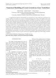
Strojniški vestnik - Journal <strong>of</strong> Mechanical Engineering 57(2011)11, 810-818a) b)Fig. 4. Adaptive refining <strong>of</strong> <strong>the</strong> mesh at <strong>the</strong> contact point(s) for <strong>the</strong> 3D model; a) remeshed contact forsingle contact, b) remeshed contact for double contactThat is <strong>the</strong> combined torsional mesh stiffness, <strong>the</strong>deformation <strong>of</strong> gear body, teeth and contact zonefor pinion and gear.2 THE COMBINED TORSIONAL MESHSTIFFNESSThe definition <strong>of</strong> <strong>the</strong> combined torsionalmesh stiffness K m used in this paper is <strong>the</strong> quotient<strong>of</strong> input load T [Nm] and driving gear hub rotationunder load T.E. [rad] [6] to [8]:TKm = TE . . . (1)This definition can be used for <strong>the</strong> dynamicsimulation <strong>of</strong> spur gear systems as it directlydescribes <strong>the</strong> relation between load torque andrelative motion <strong>of</strong> <strong>the</strong> gears.In 2001, Jia [2] introduced a commonformula describing <strong>the</strong> combined torsional meshstiffness by body and tooth bending stiffness. Thissimplification neglects <strong>the</strong> effect <strong>of</strong> <strong>the</strong> appliedtorque on <strong>the</strong> gearing's stiffness. The results from<strong>the</strong> FE model, however, show that <strong>the</strong>re is aninfluence <strong>of</strong> <strong>the</strong> torque on <strong>the</strong> resulting combinedtorsional mesh stiffness as shown in Fig. 5.The studies <strong>of</strong> <strong>the</strong> deformational behaviour<strong>of</strong> <strong>the</strong> gear wheels show that <strong>the</strong> stiffness <strong>of</strong> gearbody and teeth are almost load-independent while<strong>the</strong> contact deformation is non-linear, as a Hertziancontact occurs between <strong>the</strong> teeth <strong>of</strong> <strong>the</strong> gears. Theinfluence <strong>of</strong> <strong>the</strong> applied torque on <strong>the</strong> component’sstiffness is shown in Fig. 6. The position and width<strong>of</strong> <strong>the</strong> handover region between single and doublecontact zone are also torque-dependent which hasalso been shown previously [1].Fig. 5. <strong>Torsional</strong> mesh stiffness for a complete mesh cycle with different torque loads (model with 1:1 gearratio, 23 teeth, modulus 6 mm, steel)<strong>Calculation</strong> <strong>of</strong> <strong>the</strong> <strong>Combined</strong> <strong>Torsional</strong> <strong>Mesh</strong> <strong>Stiffness</strong> <strong>of</strong> <strong>Spur</strong> <strong>Gears</strong> with Two- and Three-DimensionalParametrical FE Models813