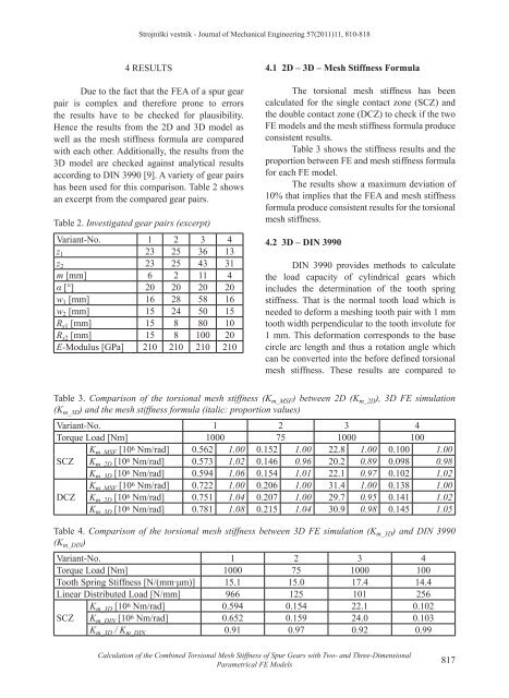
Strojniški vestnik - Journal <strong>of</strong> Mechanical Engineering 57(2011)11, 810-8184 RESULTSDue to <strong>the</strong> fact that <strong>the</strong> FEA <strong>of</strong> a spur gearpair is complex and <strong>the</strong>refore prone to errors<strong>the</strong> results have to be checked for plausibility.Hence <strong>the</strong> results from <strong>the</strong> 2D and 3D model aswell as <strong>the</strong> mesh stiffness formula are comparedwith each o<strong>the</strong>r. Additionally, <strong>the</strong> results from <strong>the</strong>3D model are checked against analytical resultsaccording to DIN 3990 [9]. A variety <strong>of</strong> gear pairshas been used for this comparison. Table 2 showsan excerpt from <strong>the</strong> compared gear pairs.Table 2. Investigated gear pairs (excerpt)Variant-No. 1 2 3 4z 1 23 25 36 13z 2 23 25 43 31m [mm] 6 2 11 4α [°] 20 20 20 20w 1 [mm] 16 28 58 16w 2 [mm] 15 24 50 15R s1 [mm] 15 8 80 10R s2 [mm] 15 8 100 20E-Modulus [GPa] 210 210 210 2104.1 2D – 3D – <strong>Mesh</strong> <strong>Stiffness</strong> FormulaThe torsional mesh stiffness has beencalculated for <strong>the</strong> single contact zone (SCZ) and<strong>the</strong> double contact zone (DCZ) to check if <strong>the</strong> twoFE models and <strong>the</strong> mesh stiffness formula produceconsistent results.Table 3 shows <strong>the</strong> stiffness results and <strong>the</strong>proportion between FE and mesh stiffness formulafor each FE model.The results show a maximum deviation <strong>of</strong>10% that implies that <strong>the</strong> FEA and mesh stiffnessformula produce consistent results for <strong>the</strong> torsionalmesh stiffness.4.2 3D – DIN 3990DIN 3990 provides methods to calculate<strong>the</strong> load capacity <strong>of</strong> cylindrical gears whichincludes <strong>the</strong> determination <strong>of</strong> <strong>the</strong> tooth springstiffness. That is <strong>the</strong> normal tooth load which isneeded to deform a meshing tooth pair with 1 mmtooth width perpendicular to <strong>the</strong> tooth involute for1 mm. This deformation corresponds to <strong>the</strong> basecircle arc length and thus a rotation angle whichcan be converted into <strong>the</strong> before defined torsionalmesh stiffness. These results are compared toTable 3. Comparison <strong>of</strong> <strong>the</strong> torsional mesh stiffness (K m_MSF ) between 2D (K m_2D ), 3D FE simulation(K m_3D ) and <strong>the</strong> mesh stiffness formula (italic: proportion values)Variant-No. 1 2 3 4Torque Load [Nm] 1000 75 1000 100K m_MSF [10 6 Nm/rad] 0.562 1.00 0.152 1.00 22.8 1.00 0.100 1.00SCZ K m_2D [10 6 Nm/rad] 0.573 1.02 0.146 0.96 20.2 0.89 0.098 0.98K m_3D [10 6 Nm/rad] 0.594 1.06 0.154 1.01 22.1 0.97 0.102 1.02K m_MSF [10 6 Nm/rad] 0.722 1.00 0.206 1.00 31.4 1.00 0.138 1.00DCZ K m_2D [10 6 Nm/rad] 0.751 1.04 0.207 1.00 29.7 0.95 0.141 1.02K m_3D [10 6 Nm/rad] 0.781 1.08 0.215 1.04 30.9 0.98 0.145 1.05Table 4. Comparison <strong>of</strong> <strong>the</strong> torsional mesh stiffness between 3D FE simulation (K m_3D ) and DIN 3990(K m_DIN )Variant-No. 1 2 3 4Torque Load [Nm] 1000 75 1000 100Tooth Spring <strong>Stiffness</strong> [N/(mm∙μm)] 15.1 15.0 17.4 14.4Linear Distributed Load [N/mm] 966 125 101 256K m_3D [10 6 Nm/rad] 0.594 0.154 22.1 0.102SCZ K m_DIN [10 6 Nm/rad] 0.652 0.159 24.0 0.103K m_3D / K m_DIN 0.91 0.97 0.92 0.99<strong>Calculation</strong> <strong>of</strong> <strong>the</strong> <strong>Combined</strong> <strong>Torsional</strong> <strong>Mesh</strong> <strong>Stiffness</strong> <strong>of</strong> <strong>Spur</strong> <strong>Gears</strong> with Two- and Three-DimensionalParametrical FE Models817
Strojniški vestnik - Journal <strong>of</strong> Mechanical Engineering 57(2011)11, 810-818results obtained by <strong>the</strong> 3D FE model in <strong>the</strong> singlecontact zone (SCZ) which is shown in Table 4.The results from <strong>the</strong> 3D FE modelreproduce <strong>the</strong> results from DIN 3990 withinan accuracy <strong>of</strong> about 10%. This shows that <strong>the</strong>results from <strong>the</strong> FEA are good. In particular if <strong>the</strong>real contact situation is taken into account whichincludes effects like friction, lubrication andtolerances a deviation <strong>of</strong> 10% has to be regardedlittle.5 CONCLUSIONThis paper presents detailed two- and threedimensionalFE models to create a set <strong>of</strong> gears andsimulate <strong>the</strong> torsional mesh stiffness for one meshcycle. By using <strong>the</strong> ANSYS parametric designlanguage <strong>the</strong> models are fully parametric and bothmodels feature an adaptive meshing algorithm for<strong>the</strong> contact zones.The 2D FE model is used to derive asimple formula for <strong>the</strong> combined torsional meshstiffness <strong>of</strong> spur gears in mesh. This formula uses<strong>the</strong> three main parts <strong>of</strong> a gear – body, teeth andcontact – to calculate <strong>the</strong> overall stiffness <strong>of</strong> <strong>the</strong>gear pair. The 3D FE model is introduced as <strong>the</strong>basis for fur<strong>the</strong>r studies. With a 3D model it willbe possible to simulate helical gears or applytooth face modifications like crowning or faceangle corrections. Fur<strong>the</strong>rmore, <strong>the</strong> influence <strong>of</strong>meshing interferences like misalignment between<strong>the</strong> gears axes due to shaft, bearing or housingdeformation and tolerances can be investigated.The resulting values from <strong>the</strong> FE modelsand <strong>the</strong> mesh stiffness formula can be used indynamic simulations such as multi body simulation<strong>of</strong> gearboxes. A benefit <strong>of</strong> <strong>the</strong> developed formulais <strong>the</strong> fact that only <strong>the</strong> basic gearing parametersare needed to derive <strong>the</strong> torsional mesh stiffness.Still <strong>the</strong> FE models feature <strong>the</strong> option to analysestresses in critical areas <strong>of</strong> <strong>the</strong> gears – for example<strong>the</strong> tooth root ‒ as well as <strong>the</strong> contact pressure on<strong>the</strong> tooth faces.A comparison <strong>of</strong> <strong>the</strong> results with eacho<strong>the</strong>r and with analytical equations shows <strong>the</strong>plausibility <strong>of</strong> both FE models and <strong>the</strong> meshstiffness formula. When compared to <strong>the</strong> realcontact situation <strong>the</strong> conducted simulations andcalculations involve some simplifications – thatis for example lubrication, friction and tolerances.Due to this <strong>the</strong> obtained results and <strong>the</strong> determineddeviations are completely satisfying.6 REFERENCES[1] Wang, J., Howard, I. (2004). The torsionalstiffness <strong>of</strong> involute spur gears. Proceedings<strong>of</strong> <strong>the</strong> Institution <strong>of</strong> Mechanical Engineers,Part C: Journal <strong>of</strong> Mechanical EngineeringScience, vol. 218, no. 1, p. 131-142.[2] Jia, S., Howard, I., Wang, J. (2001). Acommon formula for spur gear meshstiffness. Proceedings <strong>of</strong> <strong>the</strong> JSMEInternational Conference on Motion andPower Transmissions, p. 1-4.[3] Wang, J., Howard, I. (2005). Finite elementanalysis <strong>of</strong> high contact ratio spur gears inmesh. Journal <strong>of</strong> Tribology, vol. 127, no. 3,p. 469-483.[4] Jia, S., Howard, I. (2006). Comparison <strong>of</strong>localised spalling and crack damage fromdynamic modelling <strong>of</strong> spur gear vibrations.Mechanical Systems and Signal Processing,vol. 20, no. 2, p. 332-349.[5] Madenci, E., Guven, I. (2006). The finiteelement method and applications inengineering using ANSYS. Springer-Verlag,New York.[6] Wang, J., Howard, I. (2006). Comprehensiveanalysis <strong>of</strong> spur gears in mesh with varioustypes <strong>of</strong> pr<strong>of</strong>ile modifications. ProceedingsInternational Conference on MechanicalTransmissions, p. 42-47.[7] Sirichai, S. (1999). <strong>Torsional</strong> properties<strong>of</strong> spur gears in mesh using nonlinearfinite element analysis. PhD Thesis. CurtinUniversity, Perth.[8] Wang, J. (2003). Numerical andexperimental analysis <strong>of</strong> spur gears in mesh.Curtin University, Perth.[9] DIN 3990 T1 (1987). Tragfähigkeitsberechnungvon Stirnrädern - <strong>Calculation</strong><strong>of</strong> load capacity <strong>of</strong> cylindrical gears.Deutsches Institut für Normung. Berlin.818 Kiekbusch, T. ‒ Sappok, D. ‒ Sauer, B. ‒ Howard, I.