Calculation of the Combined Torsional Mesh Stiffness of Spur Gears ...
Calculation of the Combined Torsional Mesh Stiffness of Spur Gears ...
Calculation of the Combined Torsional Mesh Stiffness of Spur Gears ...

You also want an ePaper? Increase the reach of your titles
YUMPU automatically turns print PDFs into web optimized ePapers that Google loves.
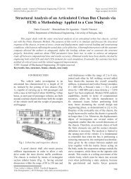
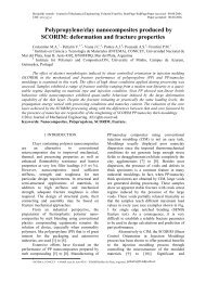
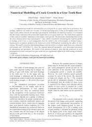
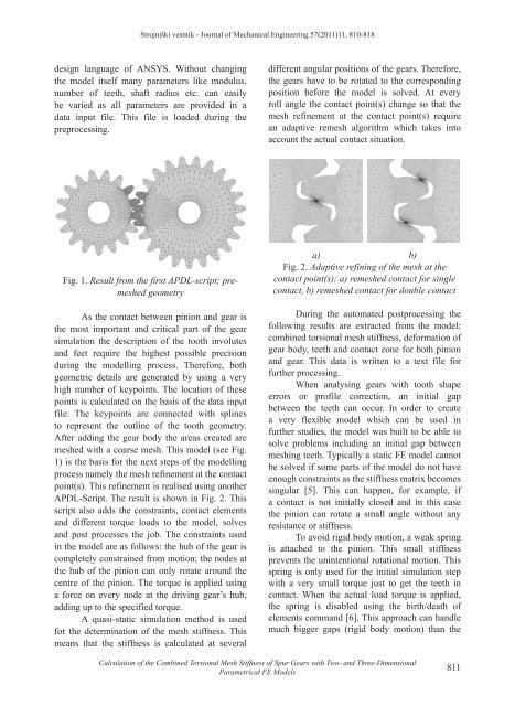
Strojniški vestnik - Journal <strong>of</strong> Mechanical Engineering 57(2011)11, 810-818design language <strong>of</strong> ANSYS. Without changing<strong>the</strong> model itself many parameters like modulus,number <strong>of</strong> teeth, shaft radius etc. can easilybe varied as all parameters are provided in adata input file. This file is loaded during <strong>the</strong>preprocessing.different angular positions <strong>of</strong> <strong>the</strong> gears. Therefore,<strong>the</strong> gears have to be rotated to <strong>the</strong> correspondingposition before <strong>the</strong> model is solved. At everyroll angle <strong>the</strong> contact point(s) change so that <strong>the</strong>mesh refinement at <strong>the</strong> contact point(s) requirean adaptive remesh algorithm which takes intoaccount <strong>the</strong> actual contact situation.Fig. 1. Result from <strong>the</strong> first APDL-script; premeshedgeometryAs <strong>the</strong> contact between pinion and gear is<strong>the</strong> most important and critical part <strong>of</strong> <strong>the</strong> gearsimulation <strong>the</strong> description <strong>of</strong> <strong>the</strong> tooth involutesand feet require <strong>the</strong> highest possible precisionduring <strong>the</strong> modelling process. Therefore, bothgeometric details are generated by using a veryhigh number <strong>of</strong> keypoints. The location <strong>of</strong> <strong>the</strong>sepoints is calculated on <strong>the</strong> basis <strong>of</strong> <strong>the</strong> data inputfile. The keypoints are connected with splinesto represent <strong>the</strong> outline <strong>of</strong> <strong>the</strong> tooth geometry.After adding <strong>the</strong> gear body <strong>the</strong> areas created aremeshed with a coarse mesh. This model (see Fig.1) is <strong>the</strong> basis for <strong>the</strong> next steps <strong>of</strong> <strong>the</strong> modellingprocess namely <strong>the</strong> mesh refinement at <strong>the</strong> contactpoint(s). This refinement is realised using ano<strong>the</strong>rAPDL-Script. The result is shown in Fig. 2. Thisscript also adds <strong>the</strong> constraints, contact elementsand different torque loads to <strong>the</strong> model, solvesand post processes <strong>the</strong> job. The constraints usedin <strong>the</strong> model are as follows: <strong>the</strong> hub <strong>of</strong> <strong>the</strong> gear iscompletely constrained from motion; <strong>the</strong> nodes at<strong>the</strong> hub <strong>of</strong> <strong>the</strong> pinion can only rotate around <strong>the</strong>centre <strong>of</strong> <strong>the</strong> pinion. The torque is applied usinga force on every node at <strong>the</strong> driving gear’s hub,adding up to <strong>the</strong> specified torque.A quasi-static simulation method is usedfor <strong>the</strong> determination <strong>of</strong> <strong>the</strong> mesh stiffness. Thismeans that <strong>the</strong> stiffness is calculated at severala) b)Fig. 2. Adaptive refining <strong>of</strong> <strong>the</strong> mesh at <strong>the</strong>contact point(s); a) remeshed contact for singlecontact, b) remeshed contact for double contactDuring <strong>the</strong> automated postprocessing <strong>the</strong>following results are extracted from <strong>the</strong> model:combined torsional mesh stiffness, deformation <strong>of</strong>gear body, teeth and contact zone for both pinionand gear. This data is written to a text file forfur<strong>the</strong>r processing.When analysing gears with tooth shapeerrors or pr<strong>of</strong>ile correction, an initial gapbetween <strong>the</strong> teeth can occur. In order to createa very flexible model which can be used infur<strong>the</strong>r studies, <strong>the</strong> model was built to be able tosolve problems including an initial gap betweenmeshing teeth. Typically a static FE model cannotbe solved if some parts <strong>of</strong> <strong>the</strong> model do not haveenough constraints as <strong>the</strong> stiffness matrix becomessingular [5]. This can happen, for example, ifa contact is not initially closed and in this case<strong>the</strong> pinion can rotate a small angle without anyresistance or stiffness.To avoid rigid body motion, a weak springis attached to <strong>the</strong> pinion. This small stiffnessprevents <strong>the</strong> unintentional rotational motion. Thisspring is only used for <strong>the</strong> initial simulation stepwith a very small torque just to get <strong>the</strong> teeth incontact. When <strong>the</strong> actual load torque is applied,<strong>the</strong> spring is disabled using <strong>the</strong> birth/death <strong>of</strong>elements command [6]. This approach can handlemuch bigger gaps (rigid body motion) than <strong>the</strong><strong>Calculation</strong> <strong>of</strong> <strong>the</strong> <strong>Combined</strong> <strong>Torsional</strong> <strong>Mesh</strong> <strong>Stiffness</strong> <strong>of</strong> <strong>Spur</strong> <strong>Gears</strong> with Two- and Three-DimensionalParametrical FE Models811