Calculation of the Combined Torsional Mesh Stiffness of Spur Gears ...
Calculation of the Combined Torsional Mesh Stiffness of Spur Gears ...
Calculation of the Combined Torsional Mesh Stiffness of Spur Gears ...

You also want an ePaper? Increase the reach of your titles
YUMPU automatically turns print PDFs into web optimized ePapers that Google loves.
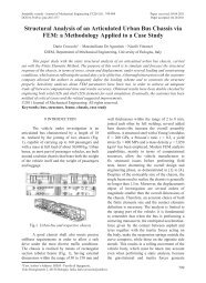
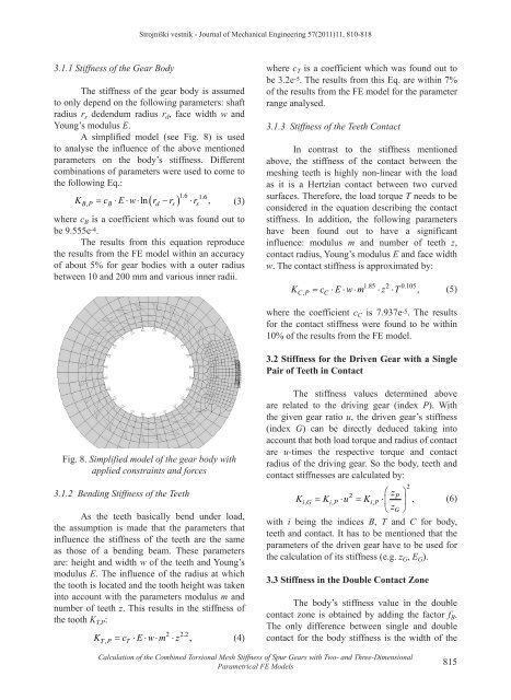
Strojniški vestnik - Journal <strong>of</strong> Mechanical Engineering 57(2011)11, 810-8183.1.1 <strong>Stiffness</strong> <strong>of</strong> <strong>the</strong> Gear BodyThe stiffness <strong>of</strong> <strong>the</strong> gear body is assumedto only depend on <strong>the</strong> following parameters: shaftradius r s dedendum radius r d , face width w andYoung’s modulus E.A simplified model (see Fig. 8) is usedto analyse <strong>the</strong> influence <strong>of</strong> <strong>the</strong> above mentionedparameters on <strong>the</strong> body’s stiffness. Differentcombinations <strong>of</strong> parameters were used to come to<strong>the</strong> following Eq.:( ) ⋅16 . 16 .BP , B d s sK = c ⋅E⋅w⋅ln r − r r ,(3)where c B is a coefficient which was found out tobe 9.555e -4 .The results from this equation reproduce<strong>the</strong> results from <strong>the</strong> FE model within an accuracy<strong>of</strong> about 5% for gear bodies with a outer radiusbetween 10 and 200 mm and various inner radii.where c T is a coefficient which was found out tobe 3.2e -5 . The results from this Eq. are within 7%<strong>of</strong> <strong>the</strong> results from <strong>the</strong> FE model for <strong>the</strong> parameterrange analysed.3.1.3 <strong>Stiffness</strong> <strong>of</strong> <strong>the</strong> Teeth ContactIn contrast to <strong>the</strong> stiffness mentionedabove, <strong>the</strong> stiffness <strong>of</strong> <strong>the</strong> contact between <strong>the</strong>meshing teeth is highly non-linear with <strong>the</strong> loadas it is a Hertzian contact between two curvedsurfaces. Therefore, <strong>the</strong> load torque T needs to beconsidered in <strong>the</strong> equation describing <strong>the</strong> contactstiffness. In addition, <strong>the</strong> following parametershave been found out to have a significantinfluence: modulus m and number <strong>of</strong> teeth z,contact radius, Young’s modulus E and face widthw. The contact stiffness is approximated by:K = c ⋅E⋅w⋅m ⋅z ⋅TCP ,C185 . 2 0.105,(5)where <strong>the</strong> coefficient c C is 7.937e -5 . The resultsfor <strong>the</strong> contact stiffness were found to be within10% <strong>of</strong> <strong>the</strong> results from <strong>the</strong> FE model.3.2 <strong>Stiffness</strong> for <strong>the</strong> Driven Gear with a SinglePair <strong>of</strong> Teeth in ContactFig. 8. Simplified model <strong>of</strong> <strong>the</strong> gear body withapplied constraints and forces3.1.2 Bending <strong>Stiffness</strong> <strong>of</strong> <strong>the</strong> TeethAs <strong>the</strong> teeth basically bend under load,<strong>the</strong> assumption is made that <strong>the</strong> parameters thatinfluence <strong>the</strong> stiffness <strong>of</strong> <strong>the</strong> teeth are <strong>the</strong> sameas those <strong>of</strong> a bending beam. These parametersare: height and width w <strong>of</strong> <strong>the</strong> teeth and Young’smodulus E. The influence <strong>of</strong> <strong>the</strong> radius at which<strong>the</strong> tooth is located and <strong>the</strong> tooth height was takeninto account with <strong>the</strong> parameters modulus m andnumber <strong>of</strong> teeth z. This results in <strong>the</strong> stiffness <strong>of</strong><strong>the</strong> tooth K T,P :K = c ⋅E⋅w⋅m ⋅ zTP ,T2 22 .,(4)The stiffness values determined aboveare related to <strong>the</strong> driving gear (index P). With<strong>the</strong> given gear ratio u, <strong>the</strong> driven gear’s stiffness(index G) can be directly deduced taking intoaccount that both load torque and radius <strong>of</strong> contactare u-times <strong>the</strong> respective torque and contactradius <strong>of</strong> <strong>the</strong> driving gear. So <strong>the</strong> body, teeth andcontact stiffnesses are calculated by:2 zPKiG , = KiP , ⋅ u = KiP, ⋅ ⎛ ,⎝ ⎜ ⎞⎟ (6)zG⎠with i being <strong>the</strong> indices B, T and C for body,teeth and contact. It has to be mentioned that <strong>the</strong>parameters <strong>of</strong> <strong>the</strong> driven gear have to be used for<strong>the</strong> calculation <strong>of</strong> its stiffness (e.g. z G , E G ).3.3 <strong>Stiffness</strong> in <strong>the</strong> Double Contact ZoneThe body’s stiffness value in <strong>the</strong> doublecontact zone is obtained by adding <strong>the</strong> factor f B .The only difference between single and doublecontact for <strong>the</strong> body stiffness is <strong>the</strong> width <strong>of</strong> <strong>the</strong>2<strong>Calculation</strong> <strong>of</strong> <strong>the</strong> <strong>Combined</strong> <strong>Torsional</strong> <strong>Mesh</strong> <strong>Stiffness</strong> <strong>of</strong> <strong>Spur</strong> <strong>Gears</strong> with Two- and Three-DimensionalParametrical FE Models815