Biuletyn Instytutu Spawalnictwa No. 01/2012
Biuletyn Instytutu Spawalnictwa No. 01/2012
Biuletyn Instytutu Spawalnictwa No. 01/2012

You also want an ePaper? Increase the reach of your titles
YUMPU automatically turns print PDFs into web optimized ePapers that Google loves.
<strong>No</strong>. <strong>01</strong>/2<strong>01</strong>2
<strong>No</strong>. <strong>01</strong>/2<strong>01</strong>2<br />
BIMONTHLY<br />
Volume 56<br />
CONTENTS<br />
• J. Dworak - Impact of laser beam shape on YAG pulsed laser welding..................... 5<br />
• A. Sawicki - Modified Habedank and TWV hybrid models of the arc with variable<br />
length for simulating processes in electrical devices ..................................................... 15<br />
• E. Turyk, A. Żydzik-Białek, M. Bormann, A. Jastrzębiowski,<br />
M. Kościelniak, T. Kuzio, B. Czwórnóg - Repair welding of elements<br />
of the sign “ARBEIT MACHT FREI” of the main gate to the former German Nazi<br />
concentration and extermination camp Auschwitz I....................................................... 23<br />
• A. Kiszka, T. Pfeifer - Variable polarity MAG welding of thin protective-coated<br />
steel plates...................................................................................................................... 33<br />
• M. St. Węglowski - Testing electromagnetic radiation of welding arcin TIG<br />
method from welding process monitoring point of view................................................ 40<br />
INSTITUTE OF WELDING<br />
The International Institute of Welding<br />
and The European Federation for Welding,<br />
Joining and Cutting member
Summaries of the articles<br />
J. Dworak - Impact of laser beam shape<br />
on YAG pulsed laser welding<br />
The study presents the general characteristic<br />
of laser welding with a radiation beam emitted<br />
in the pulsed mode and explains the characteristics<br />
of the energy-related parameters of<br />
a pulsed radiation beam. The text indicates the<br />
shape of a pulse (specific course of power changes<br />
within the duration of a pulse) as one of<br />
the parameters of a laser beam influencing the<br />
process of welding, particularly of thin precise<br />
elements. Examples of penetrations and welded<br />
joints were used to illustrate the possibility of<br />
changing the shape of a weld and the manner<br />
of weld metal crystallisation by applying laser<br />
beam pulses of diversified shapes.<br />
A. Sawicki - Modified Habedank and<br />
TWV hybrid models of the arc with<br />
variable length for simulating processes<br />
in electrical devices<br />
The paper indicates main difficulties in determination<br />
of characteristics and mathematical<br />
modelling of the electric arc. Limitations<br />
in practical use of the simplified and combined<br />
models of discharge with constant plasma column<br />
length have been pointed out. New plasma<br />
column models with variable arc length<br />
have been presented. The models consist of<br />
series or parallel connected elements corresponding<br />
to the modified Cassie-Berger and<br />
Mayr-Kulakov ones.<br />
E. Turyk, A. Żydzik-Białek, M. Bormann,<br />
A. Jastrzębiowski, M. Kościelniak,<br />
T. Kuzio, B. Czwórnóg -Repair<br />
welding of elements of the sign “ARBE-<br />
IT MACHT FREI” of the main gate to<br />
the former German Nazi concentration<br />
and extermination camp Auschwitz I<br />
The article presents theft-accompanying<br />
damage to the sign “ARBEIT MACHT FREI”<br />
and discusses the requirements of the Conservation<br />
Section of the Auschwitz-Birkenau<br />
State Museum related to the joining of the sign<br />
elements and the extent of conservation performed.<br />
The study also covers the process and<br />
results of the work regarding the technology<br />
of the repair welding of the sign carried out at<br />
Instytut <strong>Spawalnictwa</strong> and addresses the issue<br />
of welding-related technological supervision.<br />
A. Kiszka, T. Pfeifer - Variable polarity<br />
MAG welding of thin protectivecoated<br />
steel plates<br />
The study presents results of research on the<br />
application and usability of variable polarity<br />
MAG welding of thin protective-coated sheets<br />
in automotive industry. The research-related<br />
process was carried out using OTC Daihen DW<br />
300 and Cloos Qineo Champ welding devices.<br />
The study also discusses the influence of EN<br />
ratio in the course of current and voltage on<br />
the stability of process, quality of joints, and<br />
the degree of damage to protective coating.<br />
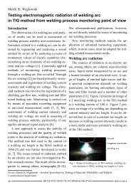
M. St. Węglowski - Testing electromagnetic<br />
radiation of welding arc in TIG<br />
method from welding process monitoring<br />
point of view<br />
The study presents the results of tests of<br />
welding arc electromagnetic radiation in TIG<br />
method. Within the research it was necessary<br />
to carry out an extensive overview of reference<br />
publications about arc radiation and applied<br />
testing methods. Taking advantage of an arc<br />
model in TIG method described in reference<br />
publications it was possible to determine a<br />
dependence of welding current intensity and<br />
welding arc length on the intensity of welding<br />
NR <strong>01</strong>/2<strong>01</strong>2<br />
BIULETYN INSTYTUTU SPAWALNICTWA<br />
3
arc visible radiation. The research-related tests<br />
made it possible to determine new parameter<br />
values in the generalised arc model for a 2÷5-<br />
mm range of welding arc length, which resulted<br />
in better matching of a model. It was also<br />
possible to demonstrate that an increase in<br />
welding current intensity for a constant length<br />
of a welding arc causes an increase in the intensity<br />
of arc visible radiation and that the<br />
same effect can be obtained by increasing an<br />
arc length at constant welding current intensity.<br />
The research also led to a conclusion that<br />
the monitoring of welding arc visible radiation<br />
in TIG method can be used for controlling an<br />
arc length.<br />
<strong>Biuletyn</strong> <strong>Instytutu</strong> <strong>Spawalnictwa</strong><br />
PL ISSN 0867-583X<br />
Publisher:<br />
Instytut <strong>Spawalnictwa</strong> (The Institute of Welding)<br />
Editor-in-chief: Prof. Jan Pilarczyk<br />
Managing editor: Alojzy Kajzerek<br />
Address:<br />
ul. Bł. Czesława 16-18, 44-100 Gliwice, Poland<br />
tel: +48 32 335 82 <strong>01</strong>(02); fax: +48 32 231 46 52<br />
E-mail: biuletyn@is.gliwice.pl;<br />
Alojzy.Kajzerek@is.gliwice.pl;<br />
Marek.Dragan@is.gliwice.pl<br />
www.bis.is.gliwice.pl<br />
<strong>Biuletyn</strong> Scientific Council:<br />
Akademik Borys E. Paton - Institut Elektrosvarki im. E.O.<br />
Patona, Kiev, Ukraine; Nacionalnaia Akademiia Nauk Ukrainy<br />
(Chairman)<br />
Prof. Luisa Countinho - European Federation for Welding,<br />
Joining and Cutting, Lisbon, Portugal<br />
Dr Mike J. Russel - The Welding Institute (TWI), Cambridge,<br />
England<br />
Prof. Andrzej Klimpel - Silesian University of Technology,<br />
Welding Department, Gliwice, Poland<br />
Prof. Jan Pilarczyk - Instytut <strong>Spawalnictwa</strong>, Gliwice, Poland<br />
<strong>Biuletyn</strong> Program Council:<br />
External members:<br />
Prof. Andrzej Ambroziak - Wrocław University<br />
of Technology,<br />
Prof. Andrzej Gruszczyk - Silesian University of Technology,<br />
Prof. Andrzej Kolasa - Warsaw University of Technology,<br />
Prof. Jerzy Łabanowski - Gdańsk University of Technology,<br />
Prof. Zbigniew Mirski - Wrocław University of Technology,<br />
Prof. Jerzy <strong>No</strong>wacki - The West Pomeranian University<br />
of Technology,<br />
Dr inż. Jan Plewniak - Częstochowa University<br />
of Technology,<br />
Prof. Jacek Senkara - Warsaw University of Technology,<br />
Prof. Edmund Tasak - AGH University of Science<br />
and Technology,<br />
International members:<br />
Prof. Peter Bernasovsky - Výskumný ústav zváračský -<br />
Priemyselný institút SR, Bratislava, Slovakia<br />
Prof. Alan Cocks - University of Oxford, England<br />
Dr Luca Costa - Istituto Italiano della Saldatura, Genoa, Italy<br />
Prof. Petar Darjanow - Technical University of Sofia,<br />
Bulgaria<br />
Prof. Dorin Dehelean - Romanian Welding Society,<br />
Timisoara, Romania<br />
Prof. Hongbiao Dong - University of Leicester, England<br />
Dr Lars Johansson - Swedish Welding Commission,<br />
Stockholm, Sweden<br />
Prof. Steffen Keitel - Gesellschaft für Schweißtechnik<br />
International mbH, Duisburg, Halle, Germany<br />
Ing. Peter Klamo - Výskumný ústav zváračský -<br />
Priemyselný institút SR, Bratislava, Slovakia<br />
Prof. Slobodan Kralj - Faculty of Mechanical Engineering<br />
and Naval Architecture, University of Zagreb, Croatia<br />
Akademik Leonid M. Łobanow - Institut Elektrosvarki<br />
im. E.O. Patona, Kiev, Ukraine;<br />
Dr Cécile Mayer - International Institute of Welding,<br />
Paris, France<br />
Prof. Dr.-Ing. Hardy Mohrbacher - NiobelCon bvba, Belgium<br />
Prof. Ian Richardson - Delft University of Technology,<br />
Netherlands<br />
Mr Michel Rousseau - Institut de Soudure, Paris, France<br />
Prof. dr Aleksander Zhelew - Schweisstechnische Lehr- und<br />
Versuchsanstalt SLV-München Bulgarien GmbH, Sofia<br />
Instytut <strong>Spawalnictwa</strong> members:<br />
dr inż. Bogusław Czwórnóg;<br />
dr hab. inż. Mirosław Łomozik, prof. I.S.;<br />
dr inż. Adam Pietras; dr inż. Piotr Sędek;<br />
dr hab. inż. Jacek Słania, prof. I.S.;<br />
dr hab. inż. Eugeniusz Turyk, prof. I.S.<br />
4 BIULETYN INSTYTUTU SPAWALNICTWA<br />
NR <strong>01</strong>/2<strong>01</strong>2
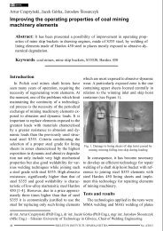
Jerzy Dworak<br />
Research<br />
Impact of laser beam shape on YAG pulsed laser welding<br />
Introduction<br />
Laser radiation beams are utilised in a variety<br />
of technological processes, having become<br />
nowadays an almost universal heat source.<br />
Typical applications such as cutting, welding<br />
and marking are being supplemented by such<br />
processes as surface hardening, surfacing by<br />
welding, re-melting, micro-machining and<br />
others. These technological processes can be<br />
carried out using various sources of laser radiation<br />
e.g. CO 2<br />
lasers, YAG lasers or HPDL<br />
lasers. YAG lasers are, at present, becoming<br />
increasingly popular, resulting from the significant<br />
power of a radiation beam (more than<br />
ten kilowatts) reached by the latest generation<br />
of devices available on the market and due<br />
to the efficient absorption of radiation, particularly<br />
by strongly reflective metals, when<br />
compared to e.g. CO 2<br />
lasers, This fact makes<br />
it possible to apply the YAG solution to an increasing<br />
number of industries, including areas<br />
which have not been available for these lasers<br />
until today.<br />
YAG lasers of power in excess of ten kilowatts<br />
constitute one of the two groups of lasers<br />
of this type. The other is composed of low-power<br />
YAG lasers (of power up to 1kW), applied<br />
mainly in precision engineering, where their<br />
position is particularly strong due to, among<br />
others, the high quality of the radiation beam.<br />
One of the characteristics of YAG lasers is<br />
the possibility of the emission of a radiation<br />
beam in a pulsed mode. High-power YAG lasers<br />
may be applied in such a mode, whereas<br />
low-power YAG lasers are usually applied in<br />
this mode.<br />
In the case of many technological processes,<br />
welding in particular, considerable importance<br />
is attached to the possibility of shaping<br />
individual radiation beam pulses through defining<br />
various courses of power changes within<br />
the duration of a pulse. The combination of the<br />
repetition frequency and the possibility of shaping<br />
a pulse within a significant pulse duration<br />
enables precise control of the heat supplied to<br />
the material being processed, which is of particular<br />
importance during the welding of precision<br />
elements using a low-power radiation<br />
beam.<br />
Power parameters of laser radiation<br />
emitted in pulsed mode<br />
The emission of YAG laser radiation in pulsed<br />
mode results from the pulsed excitation of<br />
the laser resonator. This excitation is implemented<br />
through optical pumping (the illumination<br />
of a resonator with radiation pulses of<br />
laser diodes grouped into so-called packages<br />
i.e. modules consisting of a specific number of<br />
diodes). A characteristic feature of the operation<br />
of YAG crystalline lasers is the generation<br />
of significant amounts of heat by these pumping<br />
modules, which constitutes the limitation<br />
of the maximum value of the average power<br />
and energy of a radiation beam pulse (basic<br />
parameters of the operation of pulsed lasers).<br />
The energy of a pulse depends upon the com-<br />
mgr inż. Jerzy Dworak - Instytut <strong>Spawalnictwa</strong>, Welding Technologies Department<br />
NR <strong>01</strong>/2<strong>01</strong>2<br />
BIULETYN INSTYTUTU SPAWALNICTWA<br />
5
ination of its power and width (duration).<br />
Therefore, these radiation beam parameters<br />
cannot be shaped freely, as one cannot freely<br />
define the duration and emission frequency of<br />
a pulse for the assumed value of the average<br />
power of a radiation beam. The energy of a<br />
pulse cannot exceed the maximum value defined<br />
for a given resonator.<br />
The average power of laser radiation in pulsed<br />
mode is defined as the product of the average<br />
power of the radiation of one pulse P i<br />
,<br />
the duration of this pulse t i<br />
and the number<br />
of pulses per a second expressed through the<br />
frequency of emission f. For a given average<br />
power there is a number of combinations of<br />
the selection of pulse energy and pulse repetition<br />
frequency.<br />
P śr<br />
= P i<br />
× t i<br />
× f = E i<br />
× F (1)<br />
The frequency of a pulse emission is a parameter<br />
closely related to the period of their occurrence<br />
expressed in the following relation:<br />
A weld produced by a laser beam emitted in<br />
pulsed mode is composed of a number of overlapping<br />
spot welds. The degree of overlapping<br />
of individual pulses expressed in percentage,<br />
i.e. the so-called overlap, represents the degree<br />
at which the area of a material molten by<br />
a single pulse overlaps a similar area produced<br />
by the previous pulse. By means of a specific<br />
overlap one can control the amount of heat<br />
supplied to a material being welded, as well as<br />
influence the homogeneity of the structure of<br />
a weld.<br />
The overlap is defined by the rate of the<br />
welding process appropriately selected in relation<br />
to the frequency of pulses. In turn, the<br />
frequency of pulses depends on the pre-defined<br />
power of a pulse and its duration. If an<br />
area molten by a single pulse of a laser beam<br />
takes an elliptic shape (as a result of the pro-<br />
1 ⎡ 1 ⎤<br />
T =<br />
f ⎢<br />
s =<br />
⎣ Hz ⎥ ⎦<br />
(2)<br />
The average energy of laser radiation for<br />
the pulsed operation mode is defined as the<br />
product of the average radiation power and radiation<br />
beam action time.<br />
E śr<br />
=P śr<br />
× t [J] (3)<br />
In the case of single pulse spot welding, an<br />
important parameter is the density of pulse power.<br />
GP<br />
i<br />
Pi<br />
Ei<br />
= =<br />
A t × A<br />
i<br />
⎡ J<br />
⎢<br />
⎣s<br />
⋅ m<br />
(4)<br />
where A represents the focusing area of a<br />
radiation beam.<br />
In the case of a pre-defined average power<br />
of a radiation beam P śr<br />
, the density of the power<br />
supplied to the area unit, i.e. the average<br />
2<br />
⎤<br />
⎥<br />
⎦<br />
area power density, is determined by means of<br />
the following quotient:<br />
GP<br />
śr<br />
=<br />
P<br />
śr<br />
A<br />
⎡ W<br />
⎢<br />
⎣m<br />
2<br />
⎤<br />
⎥<br />
⎦<br />
(5)<br />
The quotient of the area power density GP śr<br />
and radiation beam action time determines the<br />
average area power density:<br />
GEśr = GPśr<br />
× t<br />
⎡ J<br />
⎢<br />
⎣m<br />
(6)<br />
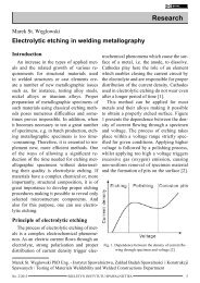
The quantities defined above are presented<br />
in Figure 1.<br />
Fig. 1. Graphic interpretation of average power of pulse<br />
P i<br />
, average power of radiation beam P śr<br />
, pulse energy E i<br />
,<br />
pulse duration t i<br />
, pause time t p<br />
pulse period T<br />
2<br />
⎤<br />
⎥<br />
⎦<br />
6 BIULETYN INSTYTUTU SPAWALNICTWA<br />
NR <strong>01</strong>/2<strong>01</strong>2
cess being carried out at a specific rate), the<br />
longer axis of the ellipse is designated as the<br />
dimension S, whereas the shorter one as the<br />
dimension D (Fig. 2,3)<br />
Fig. 2. Scheme of process of laser welding with radiation<br />
beam emitted in pulsed mode<br />
Degree of overlapping of pulses is defined<br />
by the following relation:<br />
[ ]<br />
%<br />
'<br />
S − S<br />
Z = × 100<br />
(7)<br />
S<br />
where:<br />
S = D + v × t (8)<br />
i<br />
S’ = v× T (9)<br />
After transformation of relations 7, 8, 9, the<br />
overlap Z is the following:<br />
⎡ v × T ⎤<br />
Z = ⎢1 − ⎥ ×100%<br />
(10)<br />
⎣ D + v × t i ⎦<br />
Effective penetration depth is conditioned<br />
by the overlap Z (Fig. 3).<br />
Welding with laser radiation beam emitted<br />
in pulsed mode<br />
The miniaturisation in many areas of technique<br />
has almost become a trend, stimulating<br />
the development of micro-machining (including<br />
micro-joining) of various structural materials.<br />
In relation to miniature structural elements<br />
and modules, as well as a variety of<br />
miniature components and devices, today’s<br />
manufacturing techniques and classical joining<br />
technologies in particular meet technical limitations<br />
preventing the efficient use of the former.<br />
In many applications the only solution is<br />
the laser, regarded as one of the most innovative<br />
tools of modern industry.<br />
Operating a laser in pulsed mode enables<br />
the precise production of welded joints of elements<br />
made of technologically advanced materials<br />
and having minute dimensions. A joint of<br />
this type is obtained through the melting of a<br />
very small amount of metal by a single pulse of<br />
a laser beam and its immediate crystallisation.<br />
A continuous weld is formed as a result of the<br />
proper selection of welding rate and pulse repetition<br />
frequency.<br />
Pulsed laser welding is applied where one<br />
needs to join ready-made electronic components<br />
in a tight housing, thin-walled elements<br />
(membranes) with massive cases, thin-walled<br />
housings, medical equipment elements (housings<br />
of cardiac pacemakers, endoscopes, medical<br />
implants, surgical instruments and others).<br />
Fig. 3. Graphic interpretation of overlap of pulses of laser radiation beam: v – welding rate,<br />
t i<br />
– pulse duration, D – diameter of area of focusing of radiation beam, T – pulse period [1,3]<br />
NR <strong>01</strong>/2<strong>01</strong>2<br />
BIULETYN INSTYTUTU SPAWALNICTWA<br />
7
In the pulsed laser welding process the most<br />
important issue is to ensure a slight heat impact<br />
unaccompanied by damage to the elements being<br />
joined yet accompanied by a metal-melting<br />
process. The requirements in question are met<br />
by the pulsed mode of laser operation, where<br />
relatively low average power of a radiation<br />
beam is accompanied by significant values of<br />
pulse power obtained for a very short (pulse)<br />
time. The action of a pulsed beam lasts only a<br />
few milliseconds. The molten material undergoes<br />
crystallisation before the occurrence of<br />
the next pulse. In this welding process a material<br />
is exposed to a number of pulses which<br />
melt a minimum volume of metal.<br />
The short duration of a laser radiation beam<br />
pulse in the process of welding of such materials<br />
as medical steels (some austenitic acid resistant<br />
steels e.g. X15CrNiSi20-12 (1.4828)),<br />
titanium alloys (particularly Ti6Al4V applied<br />
in medicine), dispersion-hardened aluminium<br />
alloys, and galvanised steel, may be the reason<br />
for the formation of specific imperfections in<br />
welds and of the occurrence of some technological<br />
problems (medical steels and dispersion-hardened<br />
aluminium alloys – hot cracks,<br />
titanium alloys – hardening of the joint area,<br />
galvanised steels – evaporation of zinc, impeding<br />
the process of welding) [2].<br />
It is emphasized [3,4,5] that the production<br />
of imperfection-free welds by means of a laser<br />
beam emitted in pulsed mode, particularly<br />
in the process of welding of precision elements,<br />
when, as a rule, the process of welding<br />
is carried out without adding a filler metal, is<br />
conditioned by the accurate selection of laser<br />
beam parameters. The production of a good<br />
quality weld depends on the power of the pulse<br />
(beam pulse action force) and its duration,<br />
the frequency of pulses and welding rate, the<br />
determination of the degree of overlap of the<br />
single welds formed by individual pulses of a<br />
laser beam, as well as the size of the area of<br />
a focused beam (active area), the location of<br />
the focus of the radiation beam in relation to<br />
the surface of material being welded, and the<br />
shape of a pulse.<br />
On this occasion, one should also mention<br />
the significant impact of the shape of the pulse<br />
of a laser beam emitted in pulsed mode on the<br />
elimination of welding imperfections, in particular,<br />
hot cracks [3,4,5].<br />
The focusing area is the active area of a<br />
laser beam in contact with the surface of an<br />
element being welded and is decisive for penetration<br />
depth and the width of the face of a<br />
weld. The power of a pulse represents the force<br />
with which a laser beam affects the inside<br />
of the focusing area. The higher the power of a<br />
pulse, the faster the heating of the material in<br />
the active area, though unfortunately also an<br />
increased risk of crack formation in the weld.<br />
The duration of a pulse represents the time of<br />
the action of an active radiation beam on a material,<br />
and thus is decisive for the volume of<br />
molten metal. The greater the amount of molten<br />
metal, the longer the heating and post-weld<br />
cooling times and the lower the tendency of<br />
crack formation in a weld.<br />
An important parameter is the shape of a<br />
pulse, determining the time-related course of<br />
power changes within the area of a single pulse<br />
(Fig. 4). Many devices enable the emission of<br />
Fig. 4. Example of complex shape of laser radiation beam<br />
pulse<br />
8 BIULETYN INSTYTUTU SPAWALNICTWA<br />
NR <strong>01</strong>/2<strong>01</strong>2
pulses up to several dozen milliseconds<br />
long, enabling simultaneous,<br />
almost steady, shaping of the course<br />
of power within the duration of<br />
a pulse i.e. shaping the division of<br />
pulse duration into time sub-areas<br />
(sectors) with very big density.<br />
The complex shape of a pulse is<br />
the result of the division of the basic<br />
(rectangular) pulse into sectors of specific<br />
height and width. The length of each sector can<br />
be contained within the range of 0.3ms÷50ms<br />
with an increment of 0.1ms in the case of many<br />
precise laser welding machines. The height of<br />
rectangular pulse, P i max<br />
=2250 W<br />
penetration depth h=1.52 mm<br />
face width s=1.36 mm<br />
shaped pulse, P i max<br />
=5556 W<br />
penetration depth h=1.76 mm<br />
face width s=1.67 mm<br />
shaped pulse, P i max<br />
=5556 W<br />
penetration depth h=1.91 mm<br />
face width s=1.49 mm<br />
Fig. 6. Geometry of penetrations of steel X15CrNiSi20-12 made with laser<br />
beam emitted in pulsed mode with various pulse shapes;<br />
diameter of focusing area 0.8 mm, emission frequency 5 Hz,<br />
pulse energy 18 J, pulse duration 8 ms, welding rate 1.6 mm/s [2]<br />
Fig. 5. Typical shapes of laser radiation beam pulse<br />
each sector can adopt values from the range<br />
0%÷100% of the specific power of a pulse.<br />
The shape of a pulse should be optimised in<br />
relation to the basic physicochemical properties<br />
of the material being welded, in particular<br />
to the absorptivity of surfaces being processed.<br />
The most commonly applied shapes<br />
are simple rectangular pulses (Fig.<br />
5a), rectangular pulses with a very<br />
short phase of high power and a long<br />
phase of low power (Fig. 5b) (applied<br />
while welding materials which strongly<br />
reflect radiation), and pulses with<br />
the gentle edge of radiation beam power<br />
decrease (Fig. 5c) (applied when<br />
the limitation of the dynamics of a<br />
welding thermal cycle is required e.g.<br />
in the case of materials susceptible to<br />
hot cracking).<br />
Appropriate shaping of a pulse<br />
through the composition of several<br />
phases adopting the form of a rectangular<br />
pulse and a pulse of edges<br />
of rising and falling power of a radiation<br />
beam can make it possible to<br />
produce proper joints without imperfections<br />
occurring in typical welding<br />
conditions.<br />
In the majority of typical cases it is<br />
the application of a rectangular pulse<br />
that makes it possible to obtain desirable<br />
results. As regards testing the<br />
impact of the parameters of YAG pul-<br />
NR <strong>01</strong>/2<strong>01</strong>2<br />
BIULETYN INSTYTUTU SPAWALNICTWA<br />
9
sed laser welding of various metals<br />
on the course of a welding process,<br />
research publications usually contain<br />
information about laser radiation<br />
beam pulses of a simple, rectangular<br />
shape. There are cases, however,<br />
when the application of a specific<br />
pulse shape improves the result of<br />
a welding process (enhanced seam<br />
appearance, elimination of welding<br />
imperfections). One may thus assume<br />
that the greater the density of the<br />
division of pulse duration into time<br />
sub-areas, the more effective the selection<br />
of an appropriate pulse shape<br />
(Fig. 4). The foregoing assumption<br />
allows more precise shaping of “the<br />
welding part of a pulse” and of “the<br />
control part of weld crystallisation”<br />
i.e. the function of the precise adjustment<br />
of the thermal effect of a radiation<br />
beam.<br />
Through the application of a specific<br />
laser radiation beam shape one<br />
can modify the geometry of a weld.<br />
Figures 6, 7 and 8 present the penetrations<br />
of the steel X15CrNiSi20-12<br />
acc. to PN-EN 10088-1 (mat. no.<br />
1.4828, acc. to AISI – 309) made with a rectangular<br />
pulse laser beam at the Laboratory of<br />
Laser Technologies of Instytut <strong>Spawalnictwa</strong>.<br />
In addition to the penetrations, the previously<br />
mentioned figures also contain examples of<br />
pulses shaped by means of a device TruLaser<br />
Stadion 5004 equipped with an Nd-YAG laser<br />
of the maximum average power of a radiation<br />
beam of 95 W and the maximum power of a<br />
beam pulse of 6 kW [2]. The same welding<br />
parameters (pulse power, pulse duration, emission<br />
frequency and welding rate) were applied<br />
for both shaped and rectangular pulses.<br />
10 BIULETYN INSTYTUTU SPAWALNICTWA<br />
rectangular pulse, P i max<br />
=1314 W<br />
penetration depth h=1.12 mm<br />
face width s=1.16 mm<br />
shaped pulse, P i max<br />
=3210 W<br />
penetration depth h=1.72 mm,<br />
face width s=1.36 mm<br />
shaped pulse, P i max<br />
=3210 W<br />
penetration depth h=1.51 mm<br />
face width s=1.43 mm<br />
Fig. 7. Geometry of penetrations of steel X15CrNiSi20-12 made with laser<br />
beam emitted in pulsed mode with various pulse shapes;<br />
diameter of focusing area 0.6 mm, emission frequency 8 Hz,<br />
pulse energy 10.5 J, pulse duration 8 ms, welding rate 1.9 mm/s [2]<br />
For a specific value of power and duration<br />
of a laser beam pulse having a basic rectangular<br />
shape, the average power of a pulse is<br />
similar to its maximum power, whereas in<br />
the case of a shaped pulse of the same energy<br />
(and average power), the value of the maximum<br />
power of a pulse is higher (Fig. 6),<br />
thus affecting the course of the formation of<br />
a weld.<br />
The replacement of a rectangular pulse with<br />
a shaped pulse of a prolonged edge of decreasing<br />
power resulted in a greater penetration<br />
depth and led to the advantageous modifica-<br />
NR <strong>01</strong>/2<strong>01</strong>2
ectangular pulse, P i max<br />
=702 W,<br />
penetration depth h=0.93 mm,<br />
face width s=0.87 mm<br />
shaped pulse, P i max<br />
=1584 W,<br />
penetration depth h=1.22 mm,<br />
face width s=0.92 mm<br />
shaped pulse, P i max<br />
=1584 W,<br />
penetration depth h=1.24 mm<br />
face width s=0.79 mm.<br />
shaped pulse, P i max<br />
=1422 W,<br />
penetration depth h=1.10 mm,<br />
face width s=1.30 mm.<br />
Fig. 8. Geometry of penetrations of steel X15CrNiSi20-12 made with<br />
laser beam emitted in pulsed mode with various pulse shapes;<br />
diameter of focusing area 0.3 mm, emission frequency 15 Hz,<br />
pulse energy 4.20 J, pulse duration 6 ms, welding rate 1.8 mm/s [2]<br />
tion of the shape factor (Fig. 6). Impulses of a<br />
different shape having the same energy were<br />
responsible for the formation of incompletely<br />
filled grooves despite the fact that the power<br />
of the pulse was lower [2].<br />
It should be noted that in conditions<br />
of high density of energy<br />
and high power of a pulse, only the<br />
modification of the direction of power<br />
increase or decrease at the beginning<br />
of a pulse may significantly<br />
modify welding conditions.<br />
A pulse with an initial holding<br />
phase and an increase in power at<br />
the final phase is responsible for the<br />
gouging of the material, whereas an<br />
increase in power of the same value<br />
at the beginning of a pulse and further<br />
holding phase make it possible<br />
to obtain a properly-shaped weld.<br />
These relations are different in the<br />
case of a radiation beam of different<br />
power density and pulse energy (Fig.<br />
7, 8).<br />
The appropriate shaping of a laser<br />
beam pulse may have a favourable<br />
effect on the geometry of a weld as<br />
well as positively affect the crystallisation<br />
of a weld. The foregoing<br />
is well exemplified by the melting<br />
(welding) of the aluminium alloy<br />
EN AW-5754 (EN AW-AlMg3). The<br />
penetrations (welds) made with a laser<br />
beam of a rectangular shape were<br />
characterised by the presence of clearly<br />
visible hot cracks (Fig. 9). The<br />
modification of the shape of a pulse<br />
enabled a significant reduction of<br />
these cracks (Fig. 10) [2].<br />
The laser welding of thin plates is often<br />
used to produce overlapping joints, ensuring<br />
high tolerance of the placing of elements being<br />
welded [6].<br />
NR <strong>01</strong>/2<strong>01</strong>2<br />
BIULETYN INSTYTUTU SPAWALNICTWA<br />
11
The gas-dynamic passage (capillary)<br />
formed during laser welding should<br />
be stable enough to form a vent<br />
for zinc vapours being formed. The<br />
pressure of these vapours, however,<br />
is so high that it significantly hinders<br />
the formation of a proper weld. If in<br />
the structure of the joints of galvanised<br />
plates (i.e. proper projections) no<br />
special gaps for the removal of zinc<br />
vapours were provided, the weld interface<br />
between plates being joined<br />
becomes deformed and covered with<br />
imperfections in the form of gas<br />
pores, i.e. zinc vapours confined in<br />
the weld (Fig. 11). Zinc evaporates<br />
not only in the area of molten metal<br />
where metal is being molten but also<br />
in the heat affected zone heated as<br />
a result of a welding thermal cycle.<br />
For this reason, the intensity of the<br />
evaporation depends not only on the<br />
thickness of the coating of plates being<br />
joined but also on a welding thermal<br />
cycle.<br />
In the process of laser welding<br />
using a radiation beam emitted in<br />
pulsed mode, the phenomena described<br />
above occurs with less intensity.<br />
A weld is formed by overlapping spot<br />
welds. The volume of liquid metal is<br />
smaller than in the case of laser welrectangular<br />
pulse, P i max<br />
=1752 W<br />
penetration depth h=0,2 mm<br />
face width s=0,9 mm<br />
Fig. 9. Geometry of penetration<br />
of aluminium alloy EN AW-5754<br />
(EN AW-AlMg3) made with laser<br />
beam emitted in pulsed mode of<br />
rectangular pulse shape; diameter<br />
of focusing area 0.8 mm, emission<br />
frequency 8 Hz, pulse energy<br />
10,5 J, pulse duration 6 ms,<br />
welding rate 2,6 mm/s [2]<br />
shaped pulse, P i max<br />
=3120 W<br />
penetration depth h=0,2 mm,<br />
face width s=1,0 mm<br />
Fig. 10. Geometry of penetration of<br />
aluminium alloy EN AW-5754 (EN<br />
AW-AlMg3) made with laser beam<br />
emitted in pulsed mode of special<br />
pulse shape; diameter of focusing<br />
area 0.8 mm, emission frequency<br />
8 Hz, pulse energy 10.5 J,<br />
pulse duration 6 ms,<br />
welding rate 2.6 mm/s [2]<br />
The basic problem of these types of joints<br />
in relation to galvanised plates is the area of<br />
the contact of plates subjected to melting, in<br />
which the zinc layer undergoes melting followed<br />
by evaporation. The zinc vapours may become<br />
confined in the weld, forming numerous<br />
welding imperfections and deteriorating the<br />
quality of the joint.<br />
Fig. 11. Illustration of zinc evaporation zone in process of<br />
laser welding of galvanised plates placed to form overlap<br />
joint [7]<br />
12 BIULETYN INSTYTUTU SPAWALNICTWA<br />
NR <strong>01</strong>/2<strong>01</strong>2
ectangular pulse, P i max<br />
=1752 W<br />
shaped pulse, P i max<br />
=3354 W<br />
Fig. 12. Geometry of weld in overlap joint of plates of DX-53D steel,<br />
made with laser beam emitted in pulsed mode of various pulse shape;<br />
diameter of focus area 0.8 mm, emission frequency 8 Hz, pulse energy<br />
10.5 J, pulse duration 6 ms, welding rate 2.6 mm/s [2]<br />
rectangular pulse, P i max<br />
=2628 W<br />
shaped pulse, P i max<br />
=5088 W<br />
Fig. 13. Geometry of weld in overlap joint of plates of DX-53D steel,<br />
made with laser beam emitted in pulsed mode of various pulse shape;<br />
diameter of focus area 0.8 mm, emission frequency 8 Hz, pulse energy<br />
10.5 J, pulse duration 4 ms, welding rate 2.6 mm/s [2]<br />
ding using a continuous emission laser<br />
beam. The metal becomes molten<br />
and crystallised in a cyclical manner<br />
in accordance with the laser pulse<br />
emission frequency. The re-melting<br />
of part of a weld enables the off-take<br />
of confined zinc vapours. This<br />
re-melting is also facilitated by the<br />
appropriate modulation of the course<br />
of power throughout the duration of<br />
a pulse (pulse shape).<br />
Figures 12 and 13 present the socalled<br />
“through welds” (formed by<br />
melting through one of the plates being<br />
joined) in overlap joints made of<br />
3mm-thick cold-formed galvanised<br />
low-carbon steel DX-53D (acc. to PN<br />
-EN 10346:2009). Welds were made<br />
with a laser beam of a rectangular<br />
pulse and that of shaped pulses [2].<br />
The contact gap between the plates<br />
being joined was 0.02mm÷0.04mm<br />
and provided inadequate off-take of<br />
zinc vapours while welding with a<br />
rectangular pulse. A favourable effect<br />
on the process of welding was<br />
obtained by applying laser beam pulses<br />
of a falling power curve at the final<br />
phase of a pulse.<br />
Summary<br />
The possibility of shaping the pulse<br />
of a laser radiation beam emitted<br />
in pulsed mode (i.e. the possibility of<br />
shaping changes in power within the<br />
duration of one pulse) is of significant<br />
importance particularly in laser<br />
welding of precision elements as it<br />
influences the amount of heat supplied<br />
to the material. A specific laser<br />
beam shape enables precise supply<br />
NR <strong>01</strong>/2<strong>01</strong>2<br />
BIULETYN INSTYTUTU SPAWALNICTWA<br />
13
of energy in one pulse, particularly through<br />
defining the value and location of the peak power<br />
sector of a pulse. The shape of a laser<br />
beam pulse influences the geometry of a weld<br />
and the conditions of weld crystallisation. The<br />
manner of this influence varies depending on<br />
materials, their chemical composition and<br />
state of delivery. Changing a pulse shape can<br />
help limit or eliminate welding imperfections<br />
characteristic of some metals and their alloys.<br />
The selection of pulse shape is conditioned by<br />
the rate of the change of power in time, particularly<br />
in a pulse section of descending characteristic.<br />
Pulses of complex characteristic in<br />
the area of gradual power decrease may prove<br />
their usability in the welding of numerous materials.<br />
References<br />
1. Tzeng Y-F.: Parametric analysis of the<br />
pulsed Nd:YAG laser seam-welding process.<br />
Journal of Materials Processing Technology<br />
102 (2000).<br />
2. Banasik M., Dworak J., Stano S.: Badania<br />
procesu spawania laserem impulsowym<br />
wybranych materiałów konstrukcyjnych /Tests<br />
of welding selected structural materials<br />
with pulse laser. Praca badawcza nr /Research<br />
work no./ Ci-18 (ST-279/10). Instytut <strong>Spawalnictwa</strong>,<br />
Gliwice, 2<strong>01</strong>0.<br />
3. Zhang J., Weckman D.C., Zhou Y.: Effects<br />
of temporal pulse shaping on cracking<br />
susceptibility of 6061-T6 aluminium Nd:Yag<br />
laser welds. Weld.J., 2008, nr 1.<br />
4. Naeem M. Controlling the Pulse in Laser<br />
Welding. weldingdesign.com/equipment-automation/news/wdf_11036.<br />
5. Lienert T.J., Lippold J.C.: Improved<br />
weldability diagram for pulsed laser welded<br />
austenitic stainless steels. Science and Technology<br />
of Welding and Joining, 2003, vol 8, nr<br />
1.<br />
6. Laser beam welding: benefits, strategies<br />
and applications. Weld., J., 2007, nr 5.<br />
7. Tzeng Y-F.: Pulsed Nd:YAG Laser Seam<br />
Welding of Zinc-Coated Steel. Weld., J., 1999,<br />
nr 7.<br />
8. Tzeng Y-F.: Effects of operating parameters<br />
on surface quality for the pulsed laser<br />
welding of zinc-coated steel. Journal of Materials<br />
Processing Technology 100 (2000).<br />
9. Bley H., Weyand L., Luft A.: An alternative<br />
approach for the cost-efficient laser<br />
welding of zinc-coated sheet metal. Annals of<br />
the CIRP, 2007,vol., 56, nr 1.<br />
10. Malek Ghaini F., Hamedi M.J., Torkamany<br />
M.J., Sabbaghzadeh J.: Weld metal<br />
microstructural characteristics in pulsed Nd:<br />
YAG laser welding. Scripta Materialia 56,<br />
(2007).<br />
14 BIULETYN INSTYTUTU SPAWALNICTWA<br />
NR <strong>01</strong>/2<strong>01</strong>2
Antoni Sawicki<br />
Modified Habedank and TWV hybrid models of a variable<br />
length arc for simulating processes in electrical devices<br />
Introduction<br />
The multiplicity, complexity, and problematic<br />
measurability of the characteristics of<br />
processes in arc discharges entails the necessity<br />
of applying various methods of mathematical<br />
description and quantitative analyses.<br />
Numerous physical processes including<br />
electromagnetic, thermal, gasodynamic, and<br />
acoustic as well as the mechanical processes<br />
take place in the plasma and electrodes. The<br />
complexity of such processes results from significant<br />
nonlinearities of static and dynamic<br />
characteristics, collectiveness, and interaction<br />
of plasma components as well as from<br />
the very short relaxation times of the elementary<br />
processes. Difficulties in measurability<br />
are caused by high temperatures, strong heat<br />
(and light) emission, significant gas flow rates,<br />
high quantity gradients in state variables,<br />
very high chemical reaction rates, occasional<br />
difficulties in accessing sensors (including<br />
optical ones) to a discharge area because of its<br />
small size or the fact of being closed. Due to<br />
this and depending on the needs in designing<br />
the power-supply and control systems of elecrotechnological<br />
devices, one adopts various<br />
simplifying assumptions leading to various<br />
degrees of approximation of physicochemical<br />
phenomena using mathematical models. The<br />
simplest and most commonly applied models<br />
include those of Cassie-Berger and Mayr-Kulakov.<br />
However, approximations obtained<br />
using these models are often considered to be<br />
very rough in relation to needs connected with<br />
designing and building various measuring,<br />
supply, and control systems; this being caused<br />
by a necessity to apply various electric excitations<br />
and various conditions of arc burning<br />
in devices. For this reason, various modifications<br />
of equations and new mathematical models<br />
of arcs have been proposed.<br />
Most of the existing arc models (i.e. also<br />
those by Cassie-Berger and Mayr-Kulakov)<br />
take into consideration only one manner of<br />
heat transfer, either conduction or convection,<br />
regarding each of them as dominant in<br />
a variety of technological conditions. The<br />
Cassie-Berger model provides more satisfactory<br />
results in cases when strong currents are<br />
required, whereas the Mayr-Kulakov model is<br />
preferred when weak currents are preferred.<br />
Such an approach to modelling is justified by<br />
an experimentally confirmed assumption, according<br />
to which there is a boundary between<br />
a column of thermal plasma and a turbulent<br />
gas flow around it [1].<br />
The extension of the applicability area of<br />
widely known simplified Cassie-Berger and<br />
Mayr-Kulakov models required the development<br />
of several associations. One of them is<br />
the series connection of two resistances corresponding<br />
to the nonlinear Cassie-Berger and<br />
Mayr-Kulakov models suggested by Habedank.<br />
This combined model, however, lacks<br />
appropriate physical interpretation of phenomena<br />
present in the column. A more rational<br />
solution to the issue of generalisation of description<br />
of processes taking place in the arc<br />
Dr hab. inż. Antoni Sawicki, professor at Częstochowa University of Technology – Częstochowa<br />
University of Technology, Faculty of Electrical Engineering<br />
NR <strong>01</strong>/2<strong>01</strong>2<br />
BIULETYN INSTYTUTU SPAWALNICTWA<br />
15
in a wide range of currents was proposed in<br />
publication [2], in the form of a parallel connection<br />
of conductances corresponding to the<br />
nonlinear Cassie-Berger and Mayr-Kulakov<br />
models, whose participation is determined by<br />
appropriate tapering functions of current.<br />
The basic methods of controlling welding<br />
and electrothermal (arc and plasma-arc) devices<br />
include modifications of excitation source<br />
current as well as modifications of arc (length)<br />
voltage. Most of the simple and hybrid dynamic<br />
models applied so far, however, treat<br />
the arc as an element of the constant length<br />
of a plasma column. Moreover, there are even<br />
some cases when taking into consideration the<br />
modifications of the arc length only in relation<br />
to a single model (e.g. Cassie-Berger or<br />
Mayr-Kulakov) does not ensure that the approximation<br />
of power characteristics within a<br />
wide range of work current amplitudes can be<br />
obtained.<br />
Cassie-Berger and Mayr-Kulakov models<br />
of arc with constant plasma column<br />
length<br />
Dynamic models of an electric arc column<br />
are created on the basis of the power balance<br />
equation<br />
P<br />
= u<br />
i = P<br />
kol kol dys<br />
+<br />
dQ<br />
dt<br />
(1)<br />
where P kol<br />
– power supplied to the column,<br />
P dys<br />
– thermal power dissipated from the column,<br />
Q –thermal plasma enthalpy, u kol<br />
, i –<br />
voltage and current of the arc column. The<br />
effect of strong nonlinearity of the models<br />
results from column conductance variability,<br />
which is a composite function in the form<br />
of g(t) = F g<br />
(Q(t)).<br />
Popular electric arc models by Cassie-Berger<br />
and Mayr-Kulakov take advantage of two<br />
different simplifying assumptions [3]:<br />
• Mayr-Kulakov model: T(t,(x,y,z)) = variab.,<br />
arc power dissipated through conduction<br />
⎛ QV<br />
S(i)=const; σ(i)=var; P S (i)=const; g()<br />
i = K ⋅<br />
⎜<br />
1<br />
exp<br />
⎝ Q<br />
• Cassie-Berger model: T(t,(x,y,z))=<br />
const., arc power dissipated through convection,<br />
Q () i<br />
S(i)=var; σ(i)=const; P S (i) ~ Q(i) ~ g(i) =var; g()<br />
i = K<br />
where T – temperature, K; x,y,z – system coordinates,<br />
m; S – cross-section area, m 2 , σ- plasma<br />
conductivity, S/m; P S<br />
– dissipated power,<br />
W; Q V<br />
– plasma enthalpy volumetric density,<br />
J/m 3 ; Q 0<br />
– constant reference coefficient, J/m 3 ;<br />
K 1<br />
– constant coefficient of approximation<br />
with exponential function, S/m; K 2<br />
– approximation<br />
coefficient, S. As the Mayr-Kulakov<br />
model makes it possible to obtain the best approximation<br />
in cases when weak currents are<br />
required and the Cassie-Berger model in the<br />
case of strong currents, it is the latter model<br />
that is of basic importance in simulating electromagnetic<br />
processes in industrial welding<br />
and electrothermal devices. Transitory processes<br />
in the areas of the transition of current through<br />
zero values are significant for ensuring the<br />
stability of arc burning and appropriate start<br />
and stop characteristics. In addition, the processes<br />
are decisive for the proper operation of<br />
commutation devices.<br />
After adopting appropriate simplifying<br />
assumptions and transformations [3] from formula<br />
(1), one obtains the already known Cassie-Berger<br />
models<br />
- in the conductance form<br />
1 dg<br />
g dt<br />
2<br />
1 ⎛ u ⎞<br />
kol<br />
= ⎜ −1<br />
⎟<br />
2<br />
θC<br />
⎝ U<br />
C ⎠<br />
2<br />
( σ () i )<br />
⋅<br />
0<br />
V<br />
Q<br />
0<br />
⎞<br />
⎟<br />
⎠<br />
(2)<br />
16 BIULETYN INSTYTUTU SPAWALNICTWA<br />
NR <strong>01</strong>/2<strong>01</strong>2
1 dr<br />
r dt<br />
- in the resistance form<br />
1 ⎛ u<br />
⎜1<br />
−<br />
⎝ U<br />
2<br />
=<br />
kol<br />
2<br />
θC<br />
C<br />
⎞<br />
⎟<br />
⎠<br />
(3)<br />
where ϴ C<br />
– time constant of the model, U C<br />
–<br />
model voltage, g = 1/r – conductance and resistance<br />
of the arc column.<br />
Similarly, on the basis of the power balance<br />
equation (1) and after adopting appropriate<br />
simplifying assumptions and transformations<br />
[3], one can obtain the Mayr-Kulakov models<br />
in the conductance form<br />
1<br />
g<br />
dg<br />
dt<br />
1 ⎛ u ⎞<br />
koli<br />
= ⎜ −1<br />
⎟<br />
θM<br />
⎝ PM<br />
⎠<br />
or in the resistance form<br />
1<br />
r<br />
dr<br />
dt<br />
1 ⎛ u<br />
⎜1<br />
−<br />
⎝ P<br />
=<br />
kol<br />
θM<br />
M<br />
i ⎞<br />
⎟<br />
⎠<br />
(4)<br />
(5)<br />
where U stat<br />
(i) – static voltage-current characteristics,<br />
G stat<br />
(i) – static nonlinear conductance,<br />
R(3)<br />
stat<br />
(i) – static nonlinear resistance.<br />
After substituting (8) and (9) to (6) and (7)<br />
one obtains a generalised Mayr-Kulakov equation<br />
in the conductance form<br />
1 dg 1 ⎡Gstat<br />
() i ⎤<br />
= ⎢ −1<br />
g dt θ<br />
⎥<br />
(10)<br />
Ms ⎣ g ⎦<br />
or in the resistance form<br />
1<br />
r<br />
(11)<br />
(4) When conductance does not change in time,<br />
the static characteristics of the arc in this model<br />
are as follows:<br />
U<br />
(5)<br />
dr<br />
dt<br />
1 ⎡ r<br />
() ⎥ ⎤<br />
= ⎢1<br />
−<br />
θ<br />
Ms ⎣ Rstat<br />
i ⎦<br />
() i<br />
stat<br />
=<br />
P<br />
i<br />
M<br />
(12)<br />
(1<br />
(<br />
where ϴ M<br />
– time constant of the model, P M<br />
–<br />
power of Mayr-Kulakov model.<br />
The Mayr-Kulakov arc model can be transformed<br />
into another, general conductance form<br />
1<br />
g<br />
dg<br />
dt<br />
() t<br />
1 ⎡ P<br />
() ⎥ ⎥ ⎤<br />
kol<br />
= ⎢ −1<br />
θ Ms ⎢⎣<br />
Pdys<br />
t ⎦<br />
or the resistance form<br />
(6)<br />
(13)<br />
Therefore, on the basis of these formulas<br />
one can write models (6) and (7) in the conductance<br />
form<br />
(6)<br />
1 dg 1 ⎡ i ⎤<br />
= ⎢ −1⎥ g dt θ Ms ⎣ g ⋅U<br />
stat<br />
() i ⎦<br />
1 dr 1 ⎡ P () ⎤<br />
or in the resistance form<br />
= ⎢ −<br />
kol<br />
t<br />
1 ⎥<br />
(7) (7)<br />
r dt θ<br />
Ms ⎢⎣<br />
Pdys<br />
() t ⎥ ⎦<br />
1 dr 1 ⎡ ri<br />
()<br />
where ϴ Ms<br />
– corresponds to relaxation time of<br />
⎥ ⎤<br />
= ⎢1<br />
−<br />
(15)<br />
r dt θ<br />
Ms ⎣ U<br />
stat<br />
i ⎦<br />
thermal process, and the supplied electric power<br />
amounts to<br />
U stat<br />
(i) = - U stat<br />
(-i).<br />
The application of the appropriate approximation<br />
of static characteristic U<br />
2<br />
i 2<br />
P<br />
(8)<br />
stat<br />
(i) offers more<br />
kol<br />
() t = ukoli<br />
= = i r<br />
(8)<br />
g<br />
precise determination of arc dynamic characteristics<br />
if compared with hyperbolic static characteristic,<br />
pre-set only by one constant Mayr-Ku-<br />
As the processes of heat dissipation slowly<br />
respond to external disturbance, one can assume<br />
that the power of losses is basically deterlakov<br />
power value. Such an approach extends<br />
somewhat the range of the model applicability to<br />
mined by static characteristics [4] i.e. include stronger currents, when a characteristic<br />
2<br />
i 2<br />
P () t U () i i i R () i<br />
is no longer drooping [5] but becomes flat and, in<br />
dys<br />
=<br />
stat<br />
⋅ = =<br />
stat<br />
()<br />
(9)<br />
(9)<br />
Gstat<br />
i<br />
the case of stronger currents, is even rising.<br />
G<br />
stat<br />
() i<br />
i<br />
=<br />
P<br />
2<br />
M<br />
=<br />
U<br />
i<br />
stat<br />
2<br />
=<br />
1<br />
() i ⋅i<br />
R () i<br />
stat<br />
(14)<br />
(<br />
NR <strong>01</strong>/2<strong>01</strong>2<br />
BIULETYN INSTYTUTU SPAWALNICTWA<br />
17
Combined models of arc with constant<br />
column length<br />
The series connection of the Cassie-Berger<br />
and Mayr-Kulakov models makes it possible<br />
to obtain the Habedank model, where substitute<br />
conductance fulfils the dependence<br />
(22)<br />
(23)<br />
If one now implements the simplified Mayr-Kulakov<br />
model taking into consideration the<br />
virtual static characteristics of the arc component<br />
U Mstat<br />
(i), instead of (21) one receives<br />
and after reduction<br />
1 1 1<br />
Similarly, instead of (23) the resistance<br />
= +<br />
(16)<br />
(16)<br />
g g form of the model will be<br />
M<br />
g C<br />
1<br />
r<br />
C<br />
1<br />
r<br />
M<br />
drC<br />
dt<br />
dr<br />
dt<br />
M<br />
1<br />
=<br />
θ<br />
C<br />
⎡ u<br />
⎢1<br />
−<br />
⎢⎣<br />
U<br />
2<br />
2<br />
C<br />
⎛<br />
⎜<br />
⎝<br />
rC<br />
r<br />
2<br />
⎞<br />
⎟<br />
⎠<br />
2<br />
1 ⎡ u r<br />
= ⎢ −<br />
M<br />
1<br />
θ ⎣ rP r<br />
M<br />
M<br />
⎤<br />
⎥<br />
⎥⎦<br />
⎤<br />
⎥<br />
⎦<br />
1<br />
g<br />
M<br />
1<br />
g<br />
M<br />
dg<br />
dt<br />
M<br />
dg<br />
dt<br />
M<br />
2<br />
1 ⎡ u g g ⎤<br />
= ⎢<br />
−1⎥ θ<br />
Ms ⎣i<br />
⋅U<br />
Mstat<br />
() i g<br />
M ⎦<br />
1 ⎡ u g ⎤<br />
= ⎢ −1⎥ θ ⎣ U () i g ⎦<br />
Ms<br />
Mstat<br />
M<br />
(24)<br />
(25)<br />
2<br />
and resistance is<br />
1 dr ⎡<br />
⎤<br />
M<br />
1 u rM<br />
= ⎢1<br />
−<br />
⎥ (26)<br />
rM<br />
dt θ<br />
Ms<br />
r = r M<br />
+r C<br />
(17)<br />
⎣ r ⋅i<br />
⋅U<br />
Mstat<br />
() i r ⎦<br />
As the same current flows through both elements<br />
and after taking into consideration that 1 dr ⎡ ⎤<br />
and after reduction<br />
M<br />
1 u r<br />
= ⎢ −<br />
M<br />
1<br />
⎥ (27)<br />
g C<br />
= i / u C<br />
, g M<br />
= i / u M<br />
and g = i / u it can be r<br />
⎣ () r<br />
M<br />
dt θ<br />
Ms<br />
U<br />
Mstat<br />
i ⎦<br />
stated that<br />
where<br />
g rC<br />
uC = u = u<br />
(18) U Mstat<br />
(i) (18) = U stat<br />
(i) - U 0<br />
sign(i), U C<br />
= f(U 0<br />
).<br />
gC<br />
r<br />
The voltage of U 0<br />
corresponds to ranges of<br />
and<br />
strong arc currents.<br />
g r<br />
The Habedank model (20)-(23) is sometimes<br />
used to simulate commutation processes<br />
M<br />
uM = u = u<br />
(19) (19)<br />
g<br />
M<br />
r<br />
in electric circuits with high voltage electrical<br />
Then on the basis of (18) and (19), one can<br />
devices; its expansion being the series connection<br />
of as many as three models (1 – Cas-<br />
express the Habedank model in the conductance<br />
form:<br />
sie-Berger, 2 – Mayr-Kulakov) [7]. Known as<br />
2<br />
⎡ 2<br />
1 dg 1 ⎛ ⎞ ⎤<br />
KEMA, the model was even implemented as a<br />
C u g<br />
= ⎢<br />
⎜<br />
⎟ −1⎥<br />
(20) (20)<br />
2<br />
gC<br />
dt θC<br />
⎣⎢<br />
U<br />
C ⎝ gC<br />
⎠ ⎥⎦<br />
blackbox in simulation programmes [8, 9].<br />
In the TWV hybrid arc model [2], the values<br />
of (21) currents flowing through two parallel<br />
2<br />
1 dg 1 ⎡ ⎤<br />
M<br />
u g g<br />
= ⎢ −1⎥<br />
(21)<br />
g<br />
M<br />
dt θ<br />
M ⎣ PM<br />
g<br />
M ⎦<br />
nonlinear conductances, corresponding to the<br />
The resistance form of the formulas is as follows: Mayr-Kulakov and Cassie-Berger models, depend<br />
on their resultant value and therefore can<br />
(22)<br />
be presented as follows:<br />
2<br />
⎛<br />
2<br />
⎛ i ⎞<br />
⎛<br />
()<br />
(23)<br />
⎟ ⎞<br />
⎜<br />
i ⎞<br />
i t = u<br />
⎜<br />
⎟ + ⋅ ⋅<br />
−<br />
⎜ −<br />
⎟<br />
kol<br />
g = ukol<br />
⋅ gM<br />
exp − u 1 exp<br />
2 kol<br />
gC<br />
2<br />
⎝ I0<br />
⎠ ⎝ ⎝ I0<br />
⎠⎠<br />
(28)<br />
Hence one receives<br />
g<br />
⎛ i −<br />
2<br />
⎞<br />
⎞⎞<br />
() t = g () () ⎜<br />
⎜<br />
⎟ + ⋅<br />
−<br />
⎜<br />
⎟<br />
⎟ M<br />
t ⋅ exp g<br />
2 C<br />
t 1 exp<br />
2<br />
⎝ I0<br />
⎠ ⎝ ⎝ I0<br />
⎠⎠<br />
⎛<br />
⎛ i −<br />
2<br />
(29)<br />
18 BIULETYN INSTYTUTU SPAWALNICTWA<br />
NR <strong>01</strong>/2<strong>01</strong>2
The conditions of the selection of models are<br />
as follows:<br />
- Mayr-Kulakov model<br />
In practical considerations [2] one usually<br />
assumes that ϴ (|i|) = const and G min<br />
= 0. Then,<br />
formula (32) can be simplified to<br />
g<br />
2<br />
i dg<br />
1 dg 1 ⎧ u<br />
⎫<br />
koli<br />
ukoli<br />
≈ θ (30) (30) = ⎨[ 1−<br />
ε () i ] + ε () i −1<br />
2<br />
⎬<br />
P dt<br />
g dt θ ⎩ gU<br />
C<br />
PM<br />
⎭<br />
M<br />
M<br />
() t g<br />
M<br />
() t = −<br />
M<br />
, if i < I<br />
0<br />
M<br />
- Cassie-Berger model<br />
with the designation<br />
(34)<br />
g<br />
2<br />
u i dg<br />
⎛ i<br />
≈ θ<br />
2<br />
(31) () (31)<br />
U<br />
C<br />
dt<br />
⎟ ⎞<br />
ε i = exp<br />
⎜ −<br />
(35)<br />
2<br />
⎝ I0<br />
⎠<br />
kol C<br />
C<br />
() t gC () t = −<br />
C<br />
, if i > I0<br />
In welding [10, 11] and furnace [2] arcs, the<br />
value of limiting current I0 is approximately 5<br />
A. In the case of the application of the TWV<br />
model for the approximation of the characteristics<br />
of high-pressure arc lamps, the value of<br />
I0 is almost 10 times lower [12].<br />
The hybrid model of the arc column in the<br />
conductance form is [2]<br />
g<br />
kol<br />
⎡ ⎛ i ⎞⎤<br />
u i ⎡ ⎛ i ⎞⎤<br />
i dgkol<br />
⎢1 ⎜ −<br />
⎢ ⎥<br />
I ⎟⎥<br />
U ⎜ −<br />
C ⎣ I ⎟<br />
(32)<br />
2 2<br />
2<br />
⎣ ⎝ 0 ⎠⎦<br />
⎝ 0 ⎠⎦<br />
PM<br />
dt<br />
2<br />
2 2<br />
() t =<br />
kol<br />
G + − exp⎜<br />
⎟ + exp⎜<br />
⎟ −θ<br />
( i )<br />
min<br />
(32)<br />
where G min<br />
– constant conductance dependent<br />
on the distance between electrodes, their shape<br />
and arrangement as well as on the gas and the<br />
temperature of the environment in currentless<br />
moments; I 0<br />
- transition current between the<br />
Cassie-Berger and Mayr-Kulakov models. In<br />
a general case, the suppression function ϴ depends<br />
on current i<br />
If the current is relatively low, one can assume<br />
that ϴ≈ϴ 1<br />
, and when current is high one<br />
can assume that ϴ≈ϴ 0<br />
. If ϴ→0, the static characteristic<br />
results from adopted assumptions<br />
related to the participation of individual constituent<br />
models:<br />
• if │i│ < I 0<br />
and dg/dt = 0, then u = P M<br />
/i;<br />
• if │i│ > I 0<br />
and dg/dt = 0, then u = U C<br />
sign(i).<br />
The creation of the resistance form of the<br />
hybrid model, analogous to the conductance<br />
TWV, is difficult for computer recording and<br />
implementation. For this reason, the resistance<br />
form is not subject to consideration.<br />
The TWV model is successfully used in simulations<br />
of stationary processes in welding<br />
and electrothermal devices as well as in systems<br />
with discharge light sources [2, 10-12].<br />
If here, like previously, one introduces the<br />
Mayr-Kulakov model, taking into consideration<br />
the virtual static characteristic of the arc<br />
component Ustat(iM), instead of (34) one receives<br />
At time intervals when current |i| values are<br />
low, the Mayr-Kulakov conductance constituent<br />
plays an important role and the dependence<br />
i<br />
(33) M<br />
≈i takes place. Thus, one can approximately<br />
0<br />
+ θ1<br />
( −α i )<br />
(33)<br />
write that U stat<br />
(i M<br />
) = U stat<br />
(i) and then<br />
θ = θ exp<br />
1<br />
g<br />
1<br />
g<br />
dg<br />
dt<br />
dg<br />
dt<br />
1 ⎧ ukoli<br />
ukoli<br />
= ⎨[ 1−ε<br />
() i ] + ε () i<br />
−1<br />
2<br />
θ ⎩ gU<br />
C<br />
iM<br />
⋅U<br />
stat M<br />
1 ⎧ ukoli<br />
ukol<br />
= ⎨[ 1−ε<br />
() i ] + ε () i −1<br />
2<br />
θ ⎩ gU U () i ⎭ ⎬⎫<br />
C<br />
stat<br />
( i ) ⎭ ⎬⎫<br />
(36)<br />
(37)<br />
Representation of the disturbance of<br />
arc column length with modified Cassie-Berger<br />
and Mayr-Kulakov<br />
An increase in the geometric size of the plasma<br />
arc column is accompanied by an increase<br />
in energy necessary to generate an additional<br />
NR <strong>01</strong>/2<strong>01</strong>2<br />
BIULETYN INSTYTUTU SPAWALNICTWA<br />
19
volume of plasma. The adopted assumption of<br />
the axial-cylindrical shape of the column and<br />
its stretching by length dl corresponds to an<br />
increase in thermal power<br />
dQ<br />
dt<br />
dQa<br />
dl dl<br />
= ql<br />
(38) (38)<br />
dl dt dt<br />
a<br />
=<br />
where q l<br />
– arc energy linear density. Hence<br />
in simplifying conditions, the thermal power<br />
necessary to generate the additional volume<br />
of plasma is approximately proportional to the<br />
length of the increment rate. The phenomenon<br />
is accompanied by relaxation times resulting<br />
from gas thermal inertia and additional cooling<br />
of the column. Modified equations (2) and (3),<br />
with a variable value of the Cassie-Berger<br />
Representation of disturbance of arc<br />
column length in modified Habedank<br />
and TWV hybrid models<br />
The series connection of nonlinear conductances<br />
(16) corresponding to the Cassie-Berger<br />
and Mayr-Kulakov models makes it possible<br />
to obtain the modified Habedank model.<br />
The conductance form is expressed by the following<br />
formulas:<br />
1<br />
g<br />
C<br />
dg<br />
dt<br />
C<br />
⎡<br />
⎤<br />
⎢<br />
2<br />
2<br />
1<br />
⎢<br />
u ⎛ g ⎞<br />
= −<br />
⎢<br />
⎜<br />
⎟ 1<br />
θ 2 1 ⎛ dl ⎞<br />
⎢<br />
() + ⎜ ⎟<br />
⎝ ⎠<br />
⎥ ⎥⎥⎥ C<br />
gC<br />
uC<br />
l pv<br />
⎣ gC<br />
⎝ dt ⎠ ⎦<br />
1 dg<br />
M<br />
i g dl<br />
(44)<br />
g dt<br />
= 1 ⎡<br />
⎤ 1<br />
⎢<br />
−1⎥<br />
−<br />
θ ⎛ dl ⎞<br />
M<br />
Ms ⎣ g<br />
M<br />
⋅l<br />
⋅ EMstat<br />
( i)<br />
g<br />
M ⎦ l dt<br />
voltage, U<br />
C<br />
() t = U<br />
C ⎜l,<br />
⎟ give the conductance<br />
⎝ dt ⎠<br />
If one takes into consideration the series<br />
form [13, 14]<br />
connection of resistances (17), the form of the<br />
⎛<br />
⎞<br />
⎜<br />
model will be<br />
2<br />
1 dg<br />
= 1 ⎜ ukol<br />
−<br />
⎜<br />
(39)<br />
⎛ ⎞<br />
1<br />
() ⎟ ⎟⎟⎟ (39)<br />
g dt θ 2 1 dl<br />
⎡<br />
⎤<br />
C<br />
⎜ u l + p ⎜ ⎟<br />
⎢<br />
2<br />
2<br />
C<br />
v<br />
⎝ g ⎝ dt<br />
1 drC<br />
1<br />
u<br />
⎠ ⎠<br />
⎢<br />
⎛ rC<br />
⎞<br />
= 1−<br />
(45)<br />
The resistance form is<br />
() ⎜ ⎟<br />
r ⎢ 2 ⎛ dl<br />
C<br />
dt θC<br />
⎞ ⎝ r<br />
⎢<br />
u<br />
⎠<br />
⎥ ⎥⎥⎥<br />
C<br />
l + rC<br />
⋅ pv<br />
⎜ ⎟<br />
⎣<br />
⎝ dt ⎠ ⎦<br />
⎛<br />
⎞<br />
⎜<br />
2<br />
1 dr 1 ⎜ u<br />
1 dr<br />
kol<br />
M<br />
ir r dl<br />
= 1−<br />
(40)<br />
(46)<br />
() ⎟ ⎟⎟⎟ (40)<br />
r dt θ ⎜<br />
⎛ dl<br />
C 2 ⎞<br />
r dt<br />
= 1 ⎡<br />
⎤<br />
M M<br />
1<br />
⎢1<br />
−<br />
⎥ +<br />
θ M<br />
Ms<br />
⎜ u l + rp<br />
⎣ l ⋅ EMstat<br />
() i r ⎦ l dt<br />
C<br />
v⎜<br />
⎟<br />
⎝<br />
⎝ dt ⎠ ⎠<br />
where E Mstat<br />
(i) – virtual characteristic of<br />
where p v<br />
(dl/dt) - power necessary to generate electric field intensity.<br />
additional volume of plasma.<br />
The hybrid model of the arc column, taking<br />
Kulakov proposed a modification of model into consideration its length changes, associates,<br />
by means of an appropriate tapering func-<br />
(14) taking into consideration the modification<br />
of the column length. Model I of the order in tion Ɛ(i), models (39) and (41) in the manner<br />
the conductance form is [15]<br />
(34). Thus, its form is as follows:<br />
1 dg 1 ⎡ i ⎤ 1 dl<br />
⎢ −1⎥<br />
−<br />
g dt<br />
= θ g l E () i l dt (41)<br />
Ms ⎣ ⋅ ⋅<br />
(41)<br />
1 dg<br />
stat ⎦<br />
g dt<br />
=<br />
⎧<br />
⎫<br />
where E stat<br />
(i) – static characteristic of elec-<br />
⎪<br />
2<br />
1<br />
⎪<br />
⎨[ − ukol<br />
i<br />
1 ε () i ]<br />
+ ε () i<br />
− ⎬<br />
tric field intensity. The resistance form of the θ ⎪<br />
⎛ ⎞ ⋅ ⋅<br />
()<br />
( )<br />
1<br />
2 1 dl g l Estat<br />
iM<br />
u<br />
⎪<br />
C<br />
l + pv⎜<br />
⎟<br />
⎪⎩<br />
g ⎝ dt ⎠<br />
⎪⎭<br />
model is described by the following formula:<br />
dl<br />
1 dr 1 ⎡ ir ⎤ 1 dl<br />
−ε () i 1<br />
= ⎢1<br />
− ⎥ + (42)<br />
(42)<br />
l dt<br />
(47)<br />
r dt θ<br />
Ms ⎣ l ⋅ Estat<br />
() i ⎦ l dt<br />
(43)<br />
20 BIULETYN INSTYTUTU SPAWALNICTWA<br />
NR <strong>01</strong>/2<strong>01</strong>2
Similarly as previously (37), one can write the<br />
approximate equation<br />
⎧<br />
1<br />
⎪<br />
⎨<br />
θ ⎪<br />
⎪⎩<br />
[ 1 ε () i ]<br />
1 dg<br />
g dt<br />
=<br />
⎫<br />
2<br />
u<br />
⎪<br />
kol<br />
ukol<br />
− + ε () i −1⎬<br />
2 1 ⎛ dl ⎞ l ⋅ Estat<br />
()<br />
() i<br />
u l + p ⎜ ⎟<br />
⎪<br />
C<br />
v<br />
g ⎝ dt ⎠<br />
⎪⎭<br />
dl<br />
− ε () i 1<br />
l dt<br />
(48)<br />
For simulations of processes in the circuits<br />
of electro-technological devices in which the<br />
electrode travel rate is relatively low (dl/dt≈0),<br />
formulas for the modified Habedank model are<br />
reduced to the conductance form<br />
1<br />
g<br />
C<br />
1<br />
g<br />
M<br />
dg<br />
dt<br />
C<br />
dg<br />
dt<br />
M<br />
2<br />
⎡ 2<br />
1 u ⎛ g ⎞<br />
() ⎥ ⎥ ⎤<br />
= ⎢<br />
⎜<br />
⎟ −1<br />
2<br />
θC<br />
⎣⎢<br />
uC<br />
l ⎝ gC<br />
⎠ ⎦<br />
= 1 ⎡ i g ⎤<br />
⎢<br />
− ⎥<br />
θ ⎣ ⋅ ⋅ ( )<br />
1<br />
Ms<br />
g<br />
M<br />
l EMstat<br />
i g<br />
M ⎦<br />
(49)<br />
(50)<br />
Similarly, the simplified resistance form of<br />
this model is as follows:<br />
1<br />
r<br />
C<br />
1<br />
r<br />
M<br />
drC<br />
dt<br />
dr<br />
dt<br />
M<br />
1<br />
=<br />
θ<br />
C<br />
1<br />
=<br />
θ<br />
⎡ 2 2<br />
u ⎛ r<br />
() ⎥ ⎥ ⎤<br />
C ⎞<br />
⎢1<br />
−<br />
2<br />
⎜ ⎟<br />
⎢⎣<br />
uC<br />
l ⎝ r ⎠ ⎦<br />
Ms<br />
⎡ ir<br />
⎢1<br />
−<br />
⎣ l ⋅ E<br />
M<br />
Mstat<br />
r ⎤<br />
M<br />
⎥<br />
() i r ⎦<br />
(51)<br />
(52)<br />
The simplified hybrid model of the arc column<br />
taking into consideration relatively slow<br />
changes of the length of the arc, takes the following<br />
form:<br />
1<br />
g<br />
dg<br />
dt<br />
2<br />
1 ⎧ ukol<br />
ukol<br />
= ⎨[ 1−ε<br />
() i ] + ε () i −1<br />
2<br />
θ ⎩ u () l l ⋅ E () i ⎭ ⎬⎫<br />
C<br />
stat<br />
(53)<br />
Obtained dependences (43)-(53) are relatively<br />
simple mathematical models approximating<br />
very complex physical processes taking<br />
place in high-pressure electric arcs supplied<br />
with direct or alternating current and disturbed<br />
by factors affecting the length of the plasma<br />
arc column.<br />
The macro-models of arcs and simulations<br />
of courses in circuits implemented in the programme<br />
MATLAB-Simulink can be a subject<br />
of a separate article.<br />
Conclusions<br />
1. The combined Habedank and TWV models<br />
extend the possibilities of simulating processes<br />
in electric arcs of electro-technological<br />
and electrical power engineering devices, yet<br />
only in cases in which the length of the plasma<br />
arc column is constant.<br />
2. The Cassie-Berger model extends the<br />
possibilities of simulating processes in variable<br />
length electric arcs of electro-technological<br />
and electrical power engineering devices,<br />
but (49) only in case of those with relatively high<br />
intensity of the plasma arc current.<br />
3. The Mayr-Kulakov model extends the<br />
(50)<br />
possibilities of simulating processes in variable<br />
length electric arcs of electro-technological<br />
and electrical power engineering devices,<br />
yet only in case of those with relatively low<br />
intensity (51) of the plasma arc current.<br />
4. The modified Habedank and TWV hybrid<br />
models extend the possibilities of simulating<br />
processes in electric arcs of electro-tech-<br />
(52)<br />
nological and electrical power engineering<br />
devices in which the length of the plasma arc<br />
column is changeable and the range of variability<br />
of electric current intensity is wide.<br />
5. The combined series Habedank model<br />
of the electric<br />
(53)<br />
arc, usually preferred in simulating<br />
processes in high-voltage devices, can<br />
after the implementation of necessary modification<br />
take into account the variable length of<br />
the plasma arc column.<br />
6. The combined parallel TWV model of<br />
the electric arc, usually preferred in simulating<br />
processes in low-voltage devices, can after the<br />
NR <strong>01</strong>/2<strong>01</strong>2<br />
BIULETYN INSTYTUTU SPAWALNICTWA<br />
21
implementation of necessary modification take<br />
into account the variable length of the plasma<br />
arc column.<br />
Research work funded by the Ministry<br />
of Science and Higher Education from<br />
science-allocated funds in years 2<strong>01</strong>0-2<strong>01</strong>3<br />
as research project no. N N511 305038.<br />
References:<br />
1. Krouchinin A.M., Sawicki A.: A theory<br />
of electrical arc heating. The Publishing Office<br />
of Technical University of Częstochowa, Częstochowa<br />
2003.<br />
2. King-Jet Tseng, Yaoming Wang, D. Mahinda<br />
Vilathgamuwa: An Experimentally Verified<br />
Hybrid Cassie-Mayr Electric Arc Model<br />
for Power Electronics Simulations. IEEE<br />
Transactions on Power Electronics, 1997, vol.<br />
12, nr 3, s. 429-436.<br />
3. Ciok Z.: Modele matematyczne łuku łączeniowego.<br />
Politechnika Warszawska, Warszawa<br />
1995.<br />
4. Schőtzau H. J., Kneubühl F. K.: A New<br />
Approach to High-Power Arc Dynamics.<br />
ETEP 1994, vol. 4, nr. 2, s. 89-99.<br />
5. Finkelburg W., Maecker: Elektrische<br />
Bogen und thermisches Plasma. Handbuch der<br />
Physik, 1956, Bs. XXII, S. 254-444.<br />
6. Nitu S., Nitu C., Mihalache C., Anghelita<br />
P., Pavelescu D.: Comparison between<br />
model and experiment in studying the electric<br />
arc. Journal of Optoelectronics and Advanced<br />
Materials 2008, vol. 10, nr. 5, s. 1192 – 1196.<br />
7. Koshizuka T., Shinkai T., Udagawa K.,<br />
Kawano H.: Circuit Breaker Model using Serially<br />
Connected 3 Arc Models for EMTP Simulation.<br />
International Conference on Power<br />
Systems Transients (IPST2009) in Kyoto, Japan,<br />
June 3-6, 2009.<br />
8. Gustavsson N.: Evaluation and Simulation<br />
of Black-box Arc Models for High Voltage<br />
Circuit-breakers. LiTH-ISY-EX-3492-2004,<br />
Linköping, 19 mars 2004.<br />
9. Smeets, R.P.P. and Kertész, V.: Evaluation<br />
of high-voltage circuit-breaker performance<br />
with a validated arc model. IEE Proc.,<br />
Gener. Transm. Distrib. (2000),<br />
10. Sawicki A., Świtoń Ł., Sosiński R.:<br />
Evaluation of usability of Cassie and hybrid<br />
Cassie-Mayr models to simulate processes in<br />
AC arc circuits. Przegląd Elektrotechniczny<br />
2<strong>01</strong>0, nr 1, s. 255-259.<br />
11. Sawicki A., Świtoń Ł., Sosiński R.: Process<br />
Simulation in the AC Welding Arc Circuit<br />
Using a Cassie-Mayr Hybrid Model. Suplement<br />
to the Welding Journal 2<strong>01</strong>1, March, s.<br />
41-44.<br />
12. Sawicki A., Świtoń Ł., Sosiński R.:<br />
Próba wykorzystania modeli Cassiego i hybrydowego<br />
Cassiego-Mayra do symulowania<br />
procesów w obwodach z lampami rtęciowymi.<br />
Śląskie Wiadomości Elektryczne 2<strong>01</strong>0, nr 1, s.<br />
4-9.<br />
13. Berger S.: Mathematical approach to<br />
model rapidly elongated free-burning arcs in<br />
air in electric power circuits. ICEC 2006, 6-9<br />
June 2006, Sendai, Japan, 2006.<br />
14. Berger, S.: Modell zur Berechnung des<br />
dynamischen elektrischen Verhaltens rasch<br />
verlängerter Lichtbögen. Dissertation ETH,<br />
Zürich 2009.<br />
15. Математические методы<br />
исследования динамики и проблемы<br />
управления низкотемпературной плазмой.<br />
Низкотемпературная плазма, том 2. Наука,<br />
Новосибирск 1991.<br />
22 BIULETYN INSTYTUTU SPAWALNICTWA<br />
NR <strong>01</strong>/2<strong>01</strong>2
Eugeniusz Turyk, Agnieszka Żydzik-Białek, Margrit Bormann, Andrzej Jastrzębiowski,<br />
Marta Kościelniak, Tadeusz Kuzio, Bogusław Czwórnóg<br />
Repair welding of elements of the sign ARBEIT MACHT FREI<br />
of the main gate to the former German Nazi concentration<br />
and extermination camp Auschwitz I<br />
Editor’s note<br />
After the end of the Second World War the sign “ARBEIT MACHT FREI” on the gate<br />
to the former German Nazi concentration and extermination camp Auschwitz I became one<br />
of the most important symbols of German Nazi concentration camps, slave labour, inhumane<br />
conditions and mass genocide — the Holocaust.<br />
Mieczysław Kościelniak (camp serial number 15261)<br />
“Work squads marching out to work”, Poland, 1950, from<br />
the collection of the Auschwitz-Birkenau State Museum<br />
Fig. 1. Front and back of the sign damaged during the theft. Red colour<br />
marks spots where the sign was cut or where its elements were torn<br />
off [1]<br />
Introduction<br />
In the former German Nazi concentration<br />
and extermination camp Auschwitz I in 1940,<br />
a sign reading “ARBEIT MACHT FREI”<br />
(work makes one free) was put up over the<br />
main gate. The sign was made in the shop of<br />
the camp’s locksmith under the management<br />
of Jan Liwacz (camp serial number 1<strong>01</strong>0). At<br />
night, on 17/18 December 2009 the sign was<br />
stolen from the Auschwitz-Birkenau State<br />
Museum in Oświęcim. After recovering it, it<br />
turned out that during the theft the sign (5570<br />
mm in length and 360 mm in height) sustained<br />
significant damage – it was cut into three<br />
parts, bent, the sections of the upper<br />
and lower pipes (ϕ 33x3 mm [1])<br />
were twisted and deformed and one<br />
of the letters (“I” in the word FREI)<br />
fell off (Fig. 1).<br />
After the sign had been recovered,<br />
its exceptional and symbolic<br />
significance helped to reach a decision<br />
on correcting the theft-related<br />
Mgr Agnieszka Żydzik-Białek, Dipl.-Rest. (FH) Margrit Bormann, mgr Andrzej Jastrzębiowski,<br />
mgr inż. Marta Kościelniak – the Auschwitz-Birkenau State Museum in Oświęcim, Conservation<br />
Section; dr hab. inż. Eugeniusz Turyk, mgr inż. Tadeusz Kuzio, dr inż. Bogusław Czwórnóg –<br />
Instytut <strong>Spawalnictwa</strong>, Gliwice<br />
NR <strong>01</strong>/2<strong>01</strong>2<br />
BIULETYN INSTYTUTU SPAWALNICTWA<br />
23
deformities, as they considerably distorted<br />
the primary reception of the sign. Afterwards,<br />
all the fragments were to be joined to form a<br />
whole sign again. Straightening and joining<br />
have an enormous effect on the legibility of<br />
the primary functions and meaning of the sign;<br />
therefore, the activities had to be preceded<br />
by a very thorough investigation. The fundamental<br />
assumption of the conservation was to<br />
protect all the components of the sign – pipes,<br />
letters, welds, and preserve the original paint<br />
coatings. At first, the conservators thoroughly<br />
documented the condition of the sign. In doing<br />
so they used visible light as well as ultraviolet<br />
and infrared photography. The sign was<br />
scanned in three dimensions. The tests also<br />
involved analysis of the chemical composition<br />
and hardness measurements of the material out<br />
of which the individual elements of the sign<br />
were made. Thanks to endoscopy and magnetic<br />
particle inspection it was possible to identify<br />
the slightest metal damage, invisible to the<br />
naked eye. Separate tests were carried out in<br />
relation to the protective coatings. All of these<br />
activities allowed the development of a programme<br />
of conservation [2].<br />
According to the assumptions of the conservation<br />
programme,<br />
the connections<br />
of all the<br />
elements of the<br />
sign should be<br />
stable, durable,<br />
possibly invisible,<br />
and have no<br />
detrimental effect<br />
on the appearance<br />
of the sign. It<br />
was decided that<br />
the method employed<br />
to join<br />
Sign<br />
pipe<br />
24 BIULETYN INSTYTUTU SPAWALNICTWA<br />
the elements should be the same as that applied<br />
originally, i.e. welding. Such a method should<br />
ensure a relatively narrow heat affected zone,<br />
minimum porosity, and complete penetration<br />
of the pipe joints (due to changing loads of the<br />
sign put up on the gate). Other requirements<br />
included entirely crack-free joints and as little<br />
difference in the colour of the welds and the parent<br />
metal of the elements made of carbon steel.<br />
The Conservation Section of the Auschwitz<br />
-Birkenau State Museum turned to Instytut<br />
<strong>Spawalnictwa</strong> with a request to conduct these<br />
works aimed at selecting a technology of repair<br />
welding the sign elements; the technology was<br />
to meet requirements formulated by the Conservation<br />
Section. The request also required<br />
technological supervision over the repair welding<br />
of the sign elements [5, 6]. The process<br />
and results of the conservation are presented<br />
below.<br />
Parent metal of sign elements<br />
The upper and lower seamed pipes of the historic<br />
sign are made of carbon steel having the<br />
chemical composition as presented in Table 1.<br />
Carbon steel used in the production of the<br />
sign pipes is characterised by good metallur-<br />
Table 1. Results of chemical analysis of pipe material [1] and carbon equivalent<br />
Contents of chemical elements [%]<br />
C Si Mn Cr V Ni Cu<br />
Carbon<br />
equivalent<br />
Ce [%]<br />
upper 0.0585 0.0065 0.3255 0.006 0.002 0.008 0.0228 0.12<br />
lower 0.0956 0.0065 0.4606 0.006 0.002 0.008 0.0203 0.18<br />
Lower pipe – Al content: 0.025%; P content: 0.0218%; S content: 0.0468%.<br />
Upper pipe – Al content: 0.025%; P content: 0.0268%; S content: 0.0661%.<br />
Carbon equivalent: C Mn Cr + Mo + V Ni + Cu<br />
= C + +<br />
+ ,%<br />
6 5 15<br />
Table 2. Results of chemical analysis of material of pipes technological welding tests [5]<br />
Test<br />
Contents of chemical elements [%]<br />
pipe C Si Mn Cr Mo V Ni Cu<br />
Ce [%]<br />
upper 0.065
gical weldability, confirmed by the chemical<br />
composition and related carbon equivalent.<br />
For this reason, welding of the steel does not<br />
require any special precautions aimed at preventing<br />
the formation of hardened structure in<br />
the heat affected zone.<br />
On the basis of a low silicon content<br />
(Si
Fig. 3. End of upper part (1GL acc. to 2) after word AR-<br />
BEIT<br />
Fig. 7. 120 mm-long crack of lower pipe on section 1DL<br />
acc. to Fig. 2<br />
Fig. 4. Broken end of upper pipe (1GP acc. to Fig. 2) before<br />
word MACHT<br />
Fig. 8. Ends of upper and lower pipes (2GL and 2DL acc.<br />
to Fig. 2) after word MACHT. Visible bending of upper<br />
pipe at angle of approx. 90°<br />
Fig. 5. Bent end of broken lower pipe (1DL acc. to Fig. 2)<br />
after word ARBEIT. Visible deformation of letter “T”<br />
Fig. 9. End of partly cut and broken upper pipe (2GL acc.<br />
to Fig. 2) after words MACHT<br />
Fig. 6. End of the lower pipe (1DL acc. to Fig. 2) partially<br />
cut on along its circumference and then broken<br />
Fig. 10. End of partly cut and broken upper pipe (2GP acc.<br />
to Fig. 2) before word FREI<br />
26 BIULETYN INSTYTUTU SPAWALNICTWA<br />
NR <strong>01</strong>/2<strong>01</strong>2
Damage was also caused to the welded joints<br />
between the letters and the pipes. During<br />
the visual inspection it was possible to notice<br />
cracks – welds partly or fully torn off on their<br />
whole length. Examples are presented in Figures<br />
12÷15.<br />
Fig. 11. Broken and deformed lower pipe at weld joining<br />
pipe with letter ”I” in word FREI<br />
Fig. 15. Weld joining the letter ”I” with upper pipe in<br />
word FREI – letter broken off on the whole length of welded<br />
joint (part of weld remained on pipe)<br />
Fig. 12. Torn off welds joining letter ”R” with lower pipe<br />
in word FREI<br />
It was also possible to observe cracks (Fig.<br />
16) and material torn off along the fastening<br />
on the right side the sign.<br />
Fig. 13. Crack (partly torn weld) on the length of 15 mm<br />
in weld on upper left side of letter ”E” in word FREI<br />
Fig. 14. Weld torn off, located on the upper right side of<br />
the letter ”E” in word FREI (weld torn of on the length of<br />
37.5 mm)<br />
NR <strong>01</strong>/2<strong>01</strong>2<br />
BIULETYN INSTYTUTU SPAWALNICTWA<br />
Fig. 16. Cracks in corners of right element fastening sign<br />
to pole – view from sign side<br />
In order to eliminate the adverse effect of<br />
rust and protective varnish covering the sign<br />
on the quality of the welded joints after straightening,<br />
prior to welding the zone directly<br />
adjacent to the area of planned welding underwent<br />
sand-blast cleaning. After removing<br />
paint from the existing welds and the adjacent<br />
area, it was ascertained that some cracks visible<br />
on the surface of the straightened elements<br />
were only present in the layer of the paint and<br />
not in the metal beneath it. The visual inspection<br />
also revealed the presence of residual<br />
27
welding slag (i.e. slag formed by molten electrode<br />
covering) in the welds of the letters “B”<br />
(from the front side of the sign), “E” (from the<br />
front side of the sign), “I” (from the front and<br />
back side of the sign, from the bottom) in the<br />
word ARBEIT, “M” (from the front side, from<br />
the bottom of the sign, from the left side) and<br />
the letter “C” (from the front side, from the<br />
bottom of the sign), among others. On the basis<br />
of this inspection it was possible to ascertain<br />
that the welded joints were welded manually<br />
with covered electrodes. Removal of the<br />
paint revealed welding imperfections which<br />
had been formed during the original welding<br />
of the historic sign. These faults included a<br />
burn-through in the upper joint of the letter<br />
“A” in the word ARBEIT and a gas pore in<br />
the welded joint of the bottom left base of the<br />
letter “R” in the same word, from the front<br />
side of the sign.<br />
On the basis the visual inspection of the<br />
sign, after its straightening by the artistic metalwork<br />
company EDEX-POL in Sułkowice<br />
and sand-blast cleaning of the zone directly<br />
adjacent to the area of the planned welding,<br />
a detailed list of the necessary repair welding<br />
was prepared. The scope of the work included<br />
the production of butt joints of the upper and<br />
lower pipes of the sign, welding the sign-fastening<br />
elements, as well as welding the fragments<br />
which had cracked and were torn off<br />
[6].<br />
Tests of historic sign pipe after hot<br />
straightening<br />
The damaged fragments of the sign underwent<br />
cold or hot straightening. According<br />
to information provided by the Conservation<br />
Section, in the case of hot straightening the<br />
elements were first heated up to a temperature<br />
of 830°C÷1050°C (orange colour of steel incandescence)<br />
and cooled quickly afterwards.<br />
Visual inspection did not reveal any cracks<br />
in the places adjacent to the area which had<br />
been heated.<br />
Tests of the microstructure of the historic<br />
sign pipe were conducted using the damaged<br />
section of the lower pipe, adjacent to the letter<br />
“I” (3DP acc. to Fig. 2) in the word FREI.<br />
The section in question underwent hot straightening<br />
and next, on the basis of the type<br />
and size of the damage, was qualified for a<br />
removal and replacement by a 50 mm-long<br />
insert.<br />
Before microstructural analysis the pipe<br />
material was tested for the contents of carbon,<br />
sulphur and phosphorus, which amounted to<br />
0.038%, 0.052% and 0.069% respectively.<br />
The above results, along with the results cited<br />
according to the study [1], confirmed that<br />
the chemical composition of the pipe being<br />
tested corresponded to low-carbon unalloyed<br />
structural steel. For this reason, after hot straightening<br />
followed by cooling in water, the<br />
material of the pipe should be free from disadvantageous<br />
hardened structures. In order<br />
to verify the above statement it was necessary<br />
to carry out microscopic metallographic<br />
examination of the pipe material, revealing<br />
the presence of ferritic structure with numerous<br />
non-metallic inclusions. The material<br />
of the pipe after hot straightening and fast<br />
water cooling did not reveal any hardened<br />
structures. The hardness of the pipe material<br />
measured in the metallographic specimen<br />
was between 119 HV10 and 184 HV10. The<br />
microscopic examination and hardness measurements<br />
confirmed that post-straightening<br />
repair welding did not require any additional<br />
heat treatment.<br />
28 BIULETYN INSTYTUTU SPAWALNICTWA<br />
NR <strong>01</strong>/2<strong>01</strong>2
Initial selection of method for welding<br />
the elements of the sign<br />
The initial selection of the welding method<br />
was based on the repair-related requirements<br />
enumerated above and took into consideration<br />
the arrangements made with the Conservation<br />
Section while preparing expertise and connected<br />
with the necessity to ensure a relatively<br />
narrow zone of welding-related heat effect on<br />
the material and paint cover of the pipe and<br />
a minimum weld reinforcement (aesthetical<br />
joint appearance). At this stage also the basic<br />
requirements concerning repair welding were<br />
specified.<br />
The initial selection of the repair welding<br />
method was based on the assessment of pipe joints<br />
made by means of the following methods:<br />
oxy-acetylene welding (process 311), manual<br />
metal arc welding (process 111), semi-automatic<br />
MAG welding (process 135), TIG welding<br />
(process 141), plasma arc welding (process 15)<br />
and laser beam welding (process 52).<br />
The assessment focused on the girth joints<br />
of pipes welded at Instytut <strong>Spawalnictwa</strong> using<br />
oxyacetylene welding, manual welding with<br />
covered electrodes, TIG welding and plasma<br />
arc welding as well as joints welded by outside<br />
companies (at the request of the Conservation<br />
Section) with the use of laser beam welding,<br />
MAG welding with solid wire electrode, TIG<br />
welding and combined welding i.e. a penetration<br />
layer and filling layers were made with<br />
TIG welding whereas the face layer was made<br />
with a laser beam. After analysis of these<br />
welding methods it was ascertained that the<br />
methods useful in the process of making pipe<br />
joints would be TIG welding, plasma arc welding,<br />
laser welding with backing, and a combined<br />
method i.e. penetration by means of TIG<br />
welding and the face layer using laser beam<br />
welding. The methods ensured good quality of<br />
the joints of the sign, including the pipe joints<br />
with complete penetration, minimum reinforcement<br />
and a relatively narrow heat affected<br />
zone. The torn off letters and the cracks in the<br />
welds joining the letters with the pipe could be<br />
repaired by means of plasma arc welding and<br />
TIG welding with a filler material, with fillet<br />
welds, the same as in the case of the original<br />
sign.<br />
Test welding of pipes nos. 1 and 2 supported<br />
by tests of the quality of welded joints facilitated<br />
the selection of welding consumables<br />
ensuring relatively low porosity of welded joints<br />
made of effervescing steel. Radiographic<br />
tests revealed the quality level B of girth joints<br />
made with Castolin Eutectic-manufactured<br />
rods grade CastoTIG 45255, intended for welding<br />
of unalloyed steels and ensuring the yield<br />
point of weld deposit R0.2 > 385 MPa. The<br />
tensile strength of two test pieces of the joint<br />
from pipe no. 1 was 411.5 MPa and 382.9 MPa<br />
with the rupture occurring outside the weld.<br />
Positive results of radiographic and strength<br />
tests confirmed the usability of TIG welding,<br />
plasma arc welding and rods grade CastoTIG<br />
45255W.<br />
The tests also confirmed the possibility of<br />
making irregular decorative spots on the faces<br />
of welds. The purpose of these spots, made<br />
with a pulsed laser, was to mask a characteristic<br />
arrangement of crystallisation isotherms<br />
(Fig. 17).<br />
a) b)<br />
Fig. 17. Joint of pipes (a) and laser-made decorative spots<br />
on the face of weld (b)<br />
NR <strong>01</strong>/2<strong>01</strong>2<br />
BIULETYN INSTYTUTU SPAWALNICTWA<br />
29
Tests of model joints of partly torn letters<br />
The welding test also involved carrying<br />
out model repair welding of letters partly and<br />
entirely torn off the pipe. At the first stage it<br />
was necessary to produce T-shaped joints with<br />
fillet welds, joining the letters made of 4 mm<br />
-thick steel plate with the pipe (33.9x3.2<br />
mm). Afterwards, a passage groove in the fillet<br />
weld was made (to model the crack in the<br />
lower and upper part of the weld). The cuts<br />
were welded with a plasma arc. The technological<br />
conditions of plasma welding were as<br />
follows: weld groove I, distance 1.0 mm ÷ 1.5<br />
mm, welding position PA, tungsten electrode<br />
WTh 20 1.6 mm, plasma gas Ar, shielding<br />
gas Ar+2%H2, filler material – rod CastoTIG<br />
45255W 2.0 mm in diameter, welding current<br />
22 A÷26 A, plasma gas flow rate 0.3 l/min ÷<br />
0.4 l/min, shielding gas flow rate 6 l/min. A<br />
sectional view of a model crack before and<br />
after welding is presented in Figure 18.<br />
a) b)<br />
Fig. 18. Cut in fillet weld, modelling crack along the contact<br />
line between letter and pipe (a) and macrostructure of<br />
plasma-welded cut (b)<br />
The welding tests and examinations demonstrated<br />
that the cracks in the joints between the<br />
letters and the pipe could be repaired by means<br />
of plasma arc welding and TIG welding. The<br />
application of these methods ensured proper<br />
fusion and filling of the weld groove formed<br />
through the crack.<br />
Technological supervision<br />
After the Conservation Section of the Museum<br />
had selected a company to perform repair<br />
welding i.e. company FormSerwis Sp. z<br />
o.o. (Ltd.) from Bydgoszcz, Instytut <strong>Spawalnictwa</strong><br />
carried out the following technological<br />
supervisory works:<br />
- verification of welding procedure specifications<br />
developed by the repair welding contractor.<br />
The technology developed for the<br />
welding of butt joints assumed that the root<br />
layer would be TIG welded, whereas the face<br />
layer would be laser welded. Afterwards, the<br />
face of the weld would be pulsed laser treated<br />
to obtain decorative spots,<br />
- verification of qualification certificates of<br />
personnel performing the repair welding and<br />
assessment of test joints produced within<br />
the procedure of admission of TIG welder<br />
and laser welding operator to repair welding<br />
works,<br />
- pre-welding inspection as to the completeness<br />
and serviceability of welding equipment.<br />
- supervision over the production of the joints<br />
of the sign pipes,<br />
- post-weld visual inspection of the welded<br />
joints of the sign.<br />
Welding station<br />
The welding station in a room of the<br />
locksmith’s shop of the Conservation Section<br />
of the Museum was equipped by company<br />
FormSerwis Sp. z o.o. with the following welding<br />
equipment:<br />
- device Inverter-TIG-Power 1965 DC-HF<br />
-Puls, manufactured by Italian company CE-<br />
BORA S.p.A., used for TIG welding,<br />
- device ALM 200 manufactured by company<br />
ALPHA LASER, Germany, used for laser<br />
welding and surfacing by welding with a moving<br />
head (Fig. 20), provided with a welding<br />
30 BIULETYN INSTYTUTU SPAWALNICTWA<br />
NR <strong>01</strong>/2<strong>01</strong>2
Fig. 19. Assembly table with fixed sign<br />
wire feeder. The device is equipped with a<br />
pulsed laser Nd:YAG (wavelength: 1064 nm,<br />
average power 200 W, pulse energy 90 J).<br />
The device is mobile (1400x730x1505 mm,<br />
weight 345 kg), enabling welding in various<br />
places, often difficult to access. The movements<br />
of the arm with a turn-and-tiltable laser<br />
head are controlled by an operator with a<br />
joystick. Limitations are similar to<br />
those experienced while working<br />
with a TIG welding torch.<br />
The welding station was also<br />
equipped with an assembly table<br />
provided by the Museum Preservation<br />
Department (Fig. 19).<br />
The table was used to fix and position<br />
the sign while welding so<br />
that a joint to be made was in PA<br />
position or a position close to PA<br />
(Fig. 21).<br />
Summary<br />
On the basis of the visual inspection of the<br />
damaged sign from the main gate to the former<br />
German Nazi concentration and extermination<br />
camp Auschwitz I, after its straightening and<br />
sand-blast cleaning, welding tests, examination<br />
of model joints and technological supervision<br />
over repair welding, it was possible<br />
to formulate the following conclusions:<br />
Fig. 20. Mobile laser welding machine ALM 200<br />
Fig. 21. ALM 200 laser welding of sign fixed on assembly<br />
table<br />
NR <strong>01</strong>/2<strong>01</strong>2<br />
BIULETYN INSTYTUTU SPAWALNICTWA<br />
31
1. Repair welding included the<br />
production of butt joints of the upper<br />
and lower pipes of the sign, welding<br />
of the sign-fixing elements as well as<br />
welding of cracks and torn elements<br />
according to a detailed list prepared<br />
on the basis of the visual inspection<br />
of the sign, following its straightening<br />
and sand-blast cleaning [6].<br />
2. Repair welding was carried<br />
out by company FormSerwis Sp.<br />
z o.o., following the requirements<br />
specified by the Conservation Section of the<br />
Auschwitz-Birkenau State Museum [1, 2] and<br />
Instytut <strong>Spawalnictwa</strong>.<br />
3. Visual inspection of the repair welded<br />
joints of the historic sign did not reveal any<br />
surface welding imperfections and thus confirmed<br />
the fulfilment of the acceptance criteria.<br />
During the repair welding the sign did not suffer<br />
from any deformities which would require<br />
straightening. The quality of the welded joints<br />
of the sign met the requirements of the Conservation<br />
Section of the Auschwitz-Birkenau<br />
State Museum as to the shape, dimensions and<br />
surface appearance.<br />
The conservation, straightening and integration<br />
of the damaged sign were financed<br />
by the Auschwitz-Birkenau State Museum in<br />
Oświęcim. All the work conducted by Instytut<br />
<strong>Spawalnictwa</strong> related to material testing,<br />
technology applied for welding of the sign<br />
elements, determination of the scope of repair<br />
welding works after straightening of the sign,<br />
and technological supervision over the welding<br />
of the sign [5, 6] were free of charge (as<br />
was provided in the contract concluded with<br />
the Museum).<br />
Prior to its exposition at a new main exhibition<br />
of the Museum, the re-integrated sign<br />
(Fig. 22) was subjected to further conservation.<br />
Fig. 22. Sign after welding, removed from assembly table<br />
References<br />
1. Sign ARBEIT MACHT FREI from the<br />
main gate to the camp AUSCHWITZ I. <strong>No</strong>.<br />
A-43”. Opracowanie Sekcji Konserwatorskiej<br />
Państwowego Muzeum Auschwitz-Birkenau<br />
w Oświęcimiu, 2<strong>01</strong>0 r.<br />
2. Żydzik-Białek A., Jastrzębiowski A.:<br />
Program prac konserwatorskich. Napis AR-<br />
BEIT MACHT FREI z bramy głównej byłego<br />
obozu AUSCHWITZ I. Nr inw. A-43. Sekcja<br />
Konserwatorska Państwowego Muzeum Auschwitz-Birkenau.<br />
2<strong>01</strong>0 r.<br />
3. Photographic documentation of the current<br />
state of the object. Conservation Section<br />
of the Auschwitz-Birkenau State Museum,<br />
Oświęcim, 2<strong>01</strong>1 r.<br />
4. „Mapowanie spawów obrazujące ich<br />
stan zachowania”. Sekcja Konserwatorska<br />
Państwowego Muzeum Auschwitz-Birkenau,<br />
Oświęcim, 2<strong>01</strong>1 r.<br />
5. „Wykonanie badań dotyczących wyboru<br />
technologii spawania elementów napisu AR-<br />
BEIT MACHT FREI z bramy głównej byłego<br />
obozu Auschwitz I”. Orzeczenie nr ZT/294/10,<br />
Instytut <strong>Spawalnictwa</strong>, Gliwice, 2<strong>01</strong>1 r.<br />
6. „Nadzór technologiczny przy spawaniu<br />
naprawczym elementów napisu ARBEIT<br />
MACHT FREI z bramy głównej byłego obozu<br />
Auschwitz I”. Orzeczenie nr ZT/289/11, Instytut<br />
<strong>Spawalnictwa</strong>, Gliwice, 2<strong>01</strong>1 r.<br />
32 BIULETYN INSTYTUTU SPAWALNICTWA<br />
NR <strong>01</strong>/2<strong>01</strong>2
Agnieszka Kiszka, Tomasz Pfeifer<br />
Variable polarity MAG welding of thin protective-coated<br />
steel plates<br />
Introduction<br />
Recent development in the field of modern<br />
structural materials and welding technologies<br />
has been dictated by the needs of the automotive<br />
industry. In spite of numerous attempts<br />
aimed at the implementation of such materials<br />
as magnesium and aluminium alloys, plastics,<br />
or composites, steels still dominate in the<br />
production of cars due to lower costs, better<br />
operating properties, and ease of joining. Automotive<br />
industry manufactures continually<br />
seek solutions which would allow them to obtain<br />
high-quality welds of thin steel plates provided<br />
or not provided with protective coatings.<br />
A technology currently applied in joining of<br />
3mm-thick steel plates, based on MAG welding,<br />
is unable to satisfy all quality-related<br />
requirements. Particularly problematic is the<br />
supply of excessive heat to the joint, resulting<br />
in deformations and spatters. Spatters significantly<br />
reduce the aesthetics of joints and are<br />
difficult to remove.<br />
Implementation of modern MAG welding<br />
technologies in the automotive industry<br />
has been possible thanks to newly developed<br />
solutions of advanced welding control systems.<br />
The new, so-called, low-energy methods<br />
such as CTM or ColdArc, are indented to meet<br />
requirements specified by car manufacturers.<br />
The application of low-energy welding methods<br />
decreases the amount of deformations<br />
of welded elements, reduces the number of<br />
spatters, and as a result significantly improves<br />
the appearance of joints. The most recent solution<br />
in relation to innovative MAG welding<br />
methods consists in the application of variable<br />
polarity pulsed current (Fig. 1).<br />
The study presents the analysis of technological<br />
conditions of the welding of protectivecoated<br />
structural materials. The welding methods<br />
tested in the research were those of AC<br />
Pulse, developed by a Japanese company OTC<br />
Daihen and the Cold Process, applied using<br />
Cloos-manufactured equipment. The results<br />
presented in the study were obtained at Instytut<br />
<strong>Spawalnictwa</strong> while conducting research<br />
work [1].<br />
Fig.1 Course of current in various methods of welding<br />
with consumable electrode<br />
Mgr inż. Agnieszka Kiszka, dr inż. Tomasz Pfeifer – Instytut <strong>Spawalnictwa</strong>, Zakład Technologii<br />
Spawalniczych (Department of Welding Technologies)<br />
NR <strong>01</strong>/2<strong>01</strong>2<br />
BIULETYN INSTYTUTU SPAWALNICTWA<br />
33
Course of tests and obtained results<br />
The technological tests of welding with<br />
variable polarity pulsed current were conducted<br />
on a mechanised station provided with a<br />
welding tractor equipped with holder-fixing<br />
fixtures, a guide bar, and an element for setting<br />
and fixing the position of elements to be<br />
welded. Technological tests involved the use<br />
of an OTC Daihen-manufactured device DW<br />
300 and a Cloos-made welding power source<br />
Qineo Champ 450 as well as an electrode wire<br />
PN-EN ISO 14341-A-G3Si1 of 1.0-mm and<br />
1.2-mm diameter [2]. The shielding gas used<br />
for welding with the DW 300 was a mix containing<br />
82 % Ar and 18 % CO2 (PN-EN ISO<br />
14175-M21-ArC-18). In turn, the shielding<br />
gas used for welding with the Qineo Champ<br />
Fig. 2. Course of changes in current and voltage during surfacing of zinc-coated<br />
plate using DW 300. Neutral setting of EN ratio<br />
Fig. 3. Course of changes in current and voltage during surfacing of zinc-coated<br />
plate using DW 300. Minimum EN ratio<br />
450 was a mix composed of 92% Ar and 8%<br />
CO2 (PN-EN ISO 14175-M20-ArC-8) as it<br />
was for this gas that a specified synergic line<br />
was developed and used in research-related tests.<br />
The application of another shielding gas<br />
would have impeded a welding process [3]. A<br />
gas flow rate applied in the tests was constant<br />
and amounted to 12l/min. Steels used in the<br />
tests were HX 420 LAD Z 100 MBO, HX 260<br />
LAD Z140 MBO, DX53D ZF 100 RBO, HC-<br />
T600X ZF100 RBO, H380 LAD Z140 MBO,<br />
DX56D ZF100 RBO [4, 5].<br />
Recording of course of current and<br />
voltage in time<br />
The first stage of tests consisted in recording<br />
the courses of current intensity and arc voltage<br />
in a function of time. A<br />
system for monitoring the<br />
welding process electric parameters<br />
was developed at<br />
Instytut <strong>Spawalnictwa</strong> [6].<br />
During recording, several<br />
padding welds were built up<br />
in 3mm-thick sheets. Courses<br />
were recorded for constant<br />
settings of technological<br />
parameters. The only<br />
parameter altered during<br />
recording was the percentage<br />
EN ratio (Electrode Negative<br />
ratio) in the course of<br />
welding current. The aforesaid<br />
parameter is a non-dimensional<br />
value and can be<br />
set within a range from -30<br />
to +30 (DW 300) and from –<br />
50 to + 50 (Qineo Champ).<br />
Courses for extreme settings<br />
of EN ratio are presented<br />
in Figures 2-7.<br />
34 BIULETYN INSTYTUTU SPAWALNICTWA<br />
NR <strong>01</strong>/2<strong>01</strong>2
Fig. 4. Course of changes in current and voltage during surfacing of zinc-coated<br />
plate using DW 300. Maximum EN ratio<br />
Fig. 5. Course of changes in current and voltage in function of time, recorded<br />
during surfacing of zinc-coated plate using Qineo Champ 450. Neutral setting of<br />
EN ratio<br />
Fig. 6. Course of changes in current and voltage in function of time, recorded<br />
during surfacing of zinc-coated plate using Qineo Champ 450. Maximum EN<br />
ratio<br />
Results obtained through the recording of<br />
electrical parameters during surfacing confirmed<br />
that current intensity and arc voltage indeed<br />
alter their polarity. A time-related course<br />
of welding current revealed<br />
two components of the EN<br />
ratio i.e. basic current and<br />
pulse current. Basic current<br />
maintains an arc during the<br />
change of voltage polarity;<br />
a negative pulse controls a<br />
drop of liquid filler metal.<br />
Reference publications indicate<br />
that this process takes<br />
place only for ratio values<br />
exceeding 30%; otherwise,<br />
the change of polarity may<br />
destabilise an arc [7]. As<br />
the EN ratio setting is nondimensional<br />
in the case of<br />
both devices, it is not possible<br />
to directly determine<br />
the percentage of EN ratio<br />
in the course of welding current<br />
intensity and arc voltage<br />
(works on this topic are<br />
underway). During the test<br />
it was possible to observe<br />
that there was no EN (electrode<br />
negative) for a setting<br />
ensuring the minimum EN<br />
ratio for the Qineo Champ<br />
device (Fig. 7). In the above<br />
case, the course of current is<br />
characteristic of a classical<br />
pulsed arc welding.<br />
During the recording of<br />
parameters it was possible<br />
to observe that a change of<br />
EN ratio significantly affects<br />
the course of a welding<br />
process and the appearance of padding welds.<br />
For this reason, the next stage involved technological<br />
tests of welding and surfacing with<br />
various settings of the parameter (i.e. course<br />
NR <strong>01</strong>/2<strong>01</strong>2<br />
BIULETYN INSTYTUTU SPAWALNICTWA<br />
35
Fig. 7. Course of changes in current and voltage in function of time, recorded<br />
during surfacing of zinc-coated plate using Qineo Champ 450. Minimum EN<br />
ratio<br />
of current) in order to determine its impact<br />
on the shape of weld/padding welds and the<br />
aesthetics of a welded joint.<br />
Impact of various settings of EN ratio<br />
on the course of welding process<br />
In order to determine the impact of EN ratio<br />
on the quality and geometry of a joint as well<br />
as on the depth<br />
of penetration, it<br />
was necessary to<br />
build up a number<br />
of padding welds<br />
at various settings<br />
of the parameter<br />
and with constant<br />
values of other<br />
technological parameters<br />
(filler<br />
wire feeding rate<br />
and welding rate).<br />
Padding welds<br />
were built up on<br />
3mm-thick plates<br />
of steel HX420<br />
LAD Z 100 MBO.<br />
Table 1 presents<br />
examples of the<br />
macrostructure of padding<br />
welds produced with various<br />
settings of EN ratio.<br />
Technological and macroscopic<br />
metallographic<br />
tests revealed that EN ratio<br />
affects the geometry<br />
and aesthetics of padding<br />
welds. The maximum EN<br />
ratio resulted in the smallest<br />
penetration depth, whereas<br />
the minimum EN ratio led<br />
to the greatest depth of penetration.<br />
The obtained padding welds were<br />
characterised by good quality and appearance.<br />
The surfacing process was stable and produced<br />
very few spatters, resulting in a smooth<br />
and uniform face of padding welds. Sectional<br />
views of padding welds did not reveal any welding<br />
imperfections. Only when settings were<br />
Table 1.Macrostructures of padding welds built up on 3mm-thick plates of steel HX420 LAD<br />
Z 100 MBO at various settings of EN ratio<br />
Macrostructure<br />
EN ratio<br />
AC Pule<br />
Cold Process<br />
Neutral<br />
setting<br />
of EN ratio<br />
Maximum EN<br />
ratio<br />
Minimum<br />
EN ratio<br />
<strong>No</strong>te: Adler etchant<br />
36 BIULETYN INSTYTUTU SPAWALNICTWA<br />
NR <strong>01</strong>/2<strong>01</strong>2
extreme, the process was less stable, repeatability<br />
was lower, and spatters became bigger,<br />
which significantly deteriorated the aesthetics.<br />
Another purpose of the research was to<br />
investigate the impact of EN ratio on the course<br />
of a welding process as well as on the quality<br />
and aesthetics of welded joints. The plates<br />
used for the tests were 1.5 mm thick, made<br />
of steel grade DX 53 D ZF 100 RBO and provided<br />
with a zinc-iron protective coating. The<br />
tests involved the production of overlap joints<br />
for various parameter settings and in constant<br />
welding conditions (filler wire feeding rate<br />
and welding rate). During the process, assessment<br />
was connected with the process stability.<br />
After the completion of the process, each<br />
joint underwent a visual inspection. The criterion<br />
used in the evaluation of the selection<br />
of parameters and welding conditions was the<br />
quality level B according to standard PN-EN<br />
ISO 5817 [8]. Another process-related criterion<br />
was the smallest possible damage to the<br />
zinc-iron layer. A visual inspection of joints<br />
produced at various settings of EN ratio revealed<br />
that practically in the whole range of<br />
EN ratio settings (except for extreme ones) it<br />
is possible to obtain joints<br />
of a very good quality. The<br />
smaller the EN ratio in the<br />
course the greater the damage<br />
to a zinc-iron layer<br />
near a weld. A decrease in<br />
EN ratio resulted in an increase<br />
in heat supplied to<br />
the material being welded<br />
which was manifested by<br />
an increased width of the<br />
joint overheating-affected<br />
area, greater deformations,<br />
and local burn-throughs of<br />
elements being joined.<br />
NR <strong>01</strong>/2<strong>01</strong>2<br />
BIULETYN INSTYTUTU SPAWALNICTWA<br />
Technological tests of welding of various<br />
steels with protective coatings<br />
The next stage involved technological tests<br />
related to the welding of various joints (butt,<br />
T-shaped and overlap joints) made of plates of<br />
various thicknesses. Tests revealed that MAG<br />
welding with variable polarity current makes<br />
it possible to obtain butt, T-shaped, and overlap<br />
joints characterised by very good quality.<br />
Apart from technological parameters, the basic<br />
variable affecting the possibility of joining<br />
elements and the course of a welding process<br />
is the EN ratio. Welding of thin elements is<br />
most advantageous if accompanied by a high<br />
EN ratio as it translates to small deformations<br />
and minimum damage to the zinc-iron layer. In<br />
turn, T-shaped and butt joints of greater thicknesses<br />
should be welded with a lower EN ratio<br />
as the process of welding is more “energetic”<br />
(i.e. heat input is higher). According to the test<br />
results, the appropriate selection of technological<br />
parameters makes it possible to produce<br />
overlap and butt joints of plates having as little<br />
as 0.75 mm and 0.8 mm thicknesses. Figures<br />
8-10 present selected joints and their macrostructure.<br />
Fig. 8 General view and macrostructure of overlap joint of 0.75mm-thick steel<br />
DX56D ZF100 RBO; etchant: Adler, magnification x8<br />
37
Fig. 9. Main view and macrostructure of butt joint with square preparation, made of 0.8mm<br />
-thick steel DC04+ZE 25/25 AO, test piece no. 24 from Table 9. A - view from face of weld,<br />
B- view from root of weld; etchant: Adler, magnification x8.5<br />
Fig. 10. Main view and macrostructure of butt joint with square preparation, made of<br />
3.0mm-thick steel HX 420 LAD Z 100 MBO, test piece no. 10.1 from Table 9. A - view<br />
from face of weld, B- view from root of weld; etchant: Adler, magnification x5.5<br />
A considerable advantage of MAG welding<br />
with variable polarity current is the possibility<br />
of producing inaccurately matched joints, even<br />
with a gap of 2 mm. Such a possibility is of particular<br />
importance in the automotive industry,<br />
where one often faces the necessity of welding<br />
such joints. The above mismatching is a frequent<br />
cause of such welding imperfections as burn-through<br />
or inadequate joint penetration. Elements<br />
having such imperfections are forwarded<br />
to corrective welding which increases the cost<br />
of production and the number of unacceptable<br />
products resulting in deteriorating production<br />
statistics. For this reason, technological<br />
tests included the welding of inaccurately<br />
matched overlap joints, butt joints with square<br />
preparation, and T-shaped joints. Overlap joints<br />
were made of<br />
1.2mm-thick steel<br />
HCT 600X ZF 100<br />
RBO, butt joints<br />
with square preparation<br />
were made<br />
of 3.0mm-thick<br />
steel HX 420<br />
LAD Z100 MBO,<br />
and T-shaped joints<br />
were made of<br />
2.0mm-thick steel<br />
H380 LAD Z140<br />
MBO. All the joints<br />
were made with<br />
0.5mm and 1.0mm<br />
gaps. Figures 11-<br />
13 present selected<br />
macroscopic photographs<br />
of inaccurately<br />
matched<br />
joints.<br />
Tests revealed<br />
that MAG welding with variable polarity current<br />
can be used for welding of inaccurately<br />
matched butt, T-shaped and overlap joints.<br />
Good quality, aesthetics, and an effective bridging<br />
effect were obtained for all kinds of coatings.<br />
Properly selected welding conditions<br />
can minimise or even entirely eliminate spatters.<br />
Fig. 11. Macrostructure of overlap joint of 1.2mm-thick<br />
steel HCT600X ZF 100 RBO; joint welded with 1.0 mm<br />
gap; etchant: Adler, magnification x4<br />
Fig. 12. Macrostructure of butt joint with square preparation,<br />
made of 3.0mm-thick steel HX 420 LAD Z100<br />
MBO; joint welded with 1.0 mm gap; etchant: Adler, magnification<br />
x3<br />
38 BIULETYN INSTYTUTU SPAWALNICTWA<br />
NR <strong>01</strong>/2<strong>01</strong>2
Fig. 13. Macrostructure of T-shaped joint, made of 2.0mm<br />
-thick steel H389 LAD Z140; joint welded with 0.5 mm<br />
gap; etchant: Adler, magnification x5<br />
Summary<br />
Conducted technological tests of the welding<br />
of thin plates made of unalloyed and low-alloy<br />
steels of increased strength and protected with<br />
various zinc-based coatings revealed that the<br />
application of variable polarity current makes<br />
it possible to build up joints characterised by<br />
good quality and aesthetics. A process of welding<br />
with variable polarity current is less stable<br />
than traditional MAG welding and emits specific<br />
sounds, yet joints welded in such a process<br />
are characterised by good quality and tend to<br />
be free from spatters.<br />
The basic process variables having the greatest<br />
impact on the course of the process as well<br />
as on the weldability, quality, and aesthetics of<br />
joints are the technological parameters (filler<br />
wire feeding rate, welding rate, torch inclination<br />
angle and arc length) and EN ratio in the<br />
course of welding current. A change of EN ratio<br />
significantly affects arc voltage and the amount<br />
of heat supplied to a joint. Research results revealed<br />
that the best results are achieved with<br />
neutral settings of the parameter. An increase<br />
in EN ratio reduces the penetration depth<br />
and bridging ability of an arc. If one needs to<br />
weld thin plates and avoid, as much as possible,<br />
damage to the zinc coating, a higher EN<br />
ratio should be applied in the course of current.<br />
The application of high EN ratio in the course<br />
of current also makes it possible to weld inaccurately<br />
matched joints. A decreased EN ratio<br />
increases heat input of the process and reduces<br />
the depth of penetration. T-shaped joints and<br />
thicker elements require a higher EN ratio in<br />
the course of current. The most convenient solution<br />
consists in applying a neutral EN ratio,<br />
as such an approach enables obtaining good<br />
quality welds and sufficient penetration depth.<br />
References<br />
1. Matusiak J., Pfeifer T., Wyciślik J., Kiszka<br />
A.: Analiza wpływu warunków technologicznych<br />
innowacyjnych technik spajania<br />
różnych materiałów konstrukcyjnych z nowoczesnymi<br />
powłokami ochronnymi na stan środowiska<br />
pracy. Praca badawcza <strong>Instytutu</strong> <strong>Spawalnictwa</strong><br />
nr Ma-34, Gliwice 2<strong>01</strong>1 r.<br />
2. PN-EN ISO 14341:2<strong>01</strong>1 „Materiały dodatkowe<br />
do spawania. Druty elektrodowe i stopiwo<br />
do spawania łukowego elektrodą metalową<br />
w osłonie gazu stali niestopowych<br />
i drobnoziarnistych. Klasyfikacja”<br />
3. PN-EN ISO 14175:2009 „Materiały dodatkowe<br />
do spawania. Gazy i mieszaniny gazów<br />
do spawania i procesów pokrewnych”<br />
4. PN-EN 10346:2<strong>01</strong>1 „Wyroby płaskie<br />
stalowe powlekane ogniowo w sposób ciągły.<br />
Warunki techniczne dostawy”<br />
5. PN-EN 1<strong>01</strong>52:2<strong>01</strong>1 „Wyroby płaskie<br />
stalowe walcowane na zimno ocynkowane<br />
elektrolitycznie do obróbki plastycznej na<br />
zimno. Warunki techniczne dostawy”<br />
6. Szubert L., Skoczewski P, Welcel M.:<br />
System rejestracji parametrów elektrycznych<br />
procesu spawania dla wielu stanowisk produkcyjnych.<br />
Praca badawcza <strong>Instytutu</strong> <strong>Spawalnictwa</strong><br />
nr Fc-89, Gliwice 2<strong>01</strong>0 r.<br />
7. Jaskólski K.: Robotyzacja OTC z wykorzystaniem<br />
niskoenergetycznych metod spawania.<br />
Materiały firmy SAP, 2<strong>01</strong>0<br />
8. PN-EN ISO 5817:2009 „Spawanie. Złącza<br />
spawane ze stali, niklu, tytanu i ich stopów<br />
(z wyjątkiem spawanych wiązką). Poziomy<br />
jakości według niezgodności spawalniczych”<br />
NR <strong>01</strong>/2<strong>01</strong>2<br />
BIULETYN INSTYTUTU SPAWALNICTWA<br />
39
Marek St. Węglowski<br />
Testing electromagnetic radiation of welding arc<br />
in TIG method from welding process monitoring point of view<br />
Introduction<br />
The observation of a welding arc and analysis<br />
of results can be used in assessment of<br />
welding process stability and correctness. Information<br />
related to a welding arc can be obtained<br />
by registering and analysing a sound<br />
emitted by an arc or by analysing a course of<br />
momentary values of electric quantities characterising<br />
an arc (intensity of arc welding current<br />
and arc voltage) [1]. Commonly applied<br />
methods of monitoring welding processes<br />
through a welding arc (the so-called “through<br />
the arc sensing) [2] are based primarily on measurements<br />
and registration of welding current<br />
intensity and welding arc voltage. The aforesaid<br />
methods also involve the registration of a<br />
shielding gas flow rate, welding rate and filler<br />
metal feeding rate. Monitoring is carried out<br />
by means of specialist recording equipment<br />
or universal measurement cards [1, 3]. Measurements<br />
of welding current intensity and<br />
welding arc voltage are used in assessing of<br />
welding process stability, particularly, if one<br />
applies advanced signal analysis [4].<br />
A new approach to assess the stability of<br />
welding processes and the quality of welded<br />
joints is the analysis of welding arc radiation.<br />
The method was first used in the control of<br />
a welding arc length in the MAG method in<br />
1966 [5] and was further developed in works<br />
[6, 7]. The issues related to radiation emitted<br />
by an electric arc are also investigated at Polish<br />
research centres. The result of this investigation<br />
is, among others, monographs [8-10].<br />
The aforementioned publications, however,<br />
are not directly related to issues of monitoring<br />
arc welding processes.<br />
New monitoring methods require the application<br />
of advanced measuring equipment,<br />
which, in most cases, must be adapted for welding-related<br />
measurement needs.<br />
Welding arc radiation<br />
The sources of radiation in an electric arc<br />
are, among others, arc column, near-electrode<br />
areas, liquid metal transported by an arc and<br />
a heated terminal of an electrode wire. A range<br />
of lengths of emitted light waves and their<br />
spectral composition depends on welding<br />
parameters, arc burning atmosphere, types of<br />
base and filler metals and a number of other<br />
parameters [11]. Figure 1 presents an image of<br />
a 2 mm-long welding arc in the TIG method<br />
at a welding current of 100 A. Figure 2 presents<br />
an image of a welding arc depending on<br />
current intensity and arc length. It can be observed<br />
that, in case of a constant arc length, an<br />
increase in welding current intensity results in<br />
a more stable and more symmetric welding arc<br />
of the TIG method.<br />
Fig. 1. Shape of welding arc in TIG method, welding current<br />
intensity I=100A, welding arc length L=2 mm<br />
Dr inż. Marek St. Węglowski – Instytut <strong>Spawalnictwa</strong>, Testing of Materials Weldability and Welded<br />
Constructions Department<br />
40 BIULETYN INSTYTUTU SPAWALNICTWA<br />
NR <strong>01</strong>/2<strong>01</strong>2
L=1 mm, I=25 A L=1 mm, I=50 A L=1 mm, I=75 A<br />
L=1 mm, I=100 A<br />
L=2 mm, I=25 A L=2 mm, I=50 A L=2 mm, I=75 A<br />
L=2 mm, I=100 A<br />
L=3 mm, I=25 A L=3 mm, I=50 A L=3 mm, I=75 A<br />
L=3 mm, I=100 A<br />
L=4 mm, I=25 A L=4 mm, I=50 A L=4 mm, I=75 A<br />
L=4 mm, I=100 A<br />
L=5 mm, I=25 A L=5 mm, I=50 A L=5 mm, I=75 A<br />
L=5 mm, I=100 A<br />
Fig. 2. Image of welding arc in TIG method for arc length in range from 1 to 5-mm and current intensity<br />
from 25 to 100 A; shielding gas: argon<br />
Energy emitted in an arc column is mainly<br />
scattered by conduction and convection.<br />
Emission of electromagnetic radiation constitutes<br />
10÷15% of energy supplied to an arc<br />
[11]. Heat radiation, the source of which is a<br />
body emitting high temperature, is characterised<br />
by a continuous radiation spectrum. The<br />
source of a continuous spectrum in the area<br />
of a welding arc is mainly a liquid weld pool<br />
[12]. The characteristic radiation of atoms and<br />
ions in an arc is discrete. This type of radiation<br />
is analysed in reference publications as plasma<br />
radiation.<br />
Plasma of a temperature contained in a range<br />
between several eV and a few dozen keV<br />
(in energy scale 1 eV = 11600 K) emits infrared<br />
radiation, visible radiation, ultraviolet<br />
radiation and X-ray radiation, which, due to<br />
the mechanism of emission can be divided into<br />
three basic types [14]:<br />
NR <strong>01</strong>/2<strong>01</strong>2<br />
BIULETYN INSTYTUTU SPAWALNICTWA<br />
41
1. linear radiation emitted during the transition<br />
of atoms or ions from one discrete energy level<br />
to another (transition between bound states);<br />
2. recombination radiation accompanying a<br />
capture of a free electron by one of the discrete<br />
atom or ion levels (transition between a free<br />
state and bound states);<br />
3. radiation of free electron retardation in an<br />
ion field (transitions between free states).<br />
The total radiation of welding arc plasma is<br />
the sum of the continuous radiation and linear<br />
radiation of spectral lines [10, 15]. This sum<br />
can be written as [15]:<br />
λ<br />
= ε<br />
λ, c λ,<br />
L<br />
+ ∑ε<br />
ε<br />
(1)<br />
where: ε λ,c<br />
- intensity of continuous spectrum<br />
radiation, ε λ,L<br />
- intensity of spectral line; the<br />
summation on the right side of the equation is<br />
carried out including all lines lying in a given<br />
area.<br />
For optically thin plasma, the intensity of<br />
continuous spectrum radiation can be written<br />
in the following form [15] :<br />
⎛ ⎛ hc ⎞⎞<br />
ε<br />
λ,<br />
c = kλ,<br />
c<br />
( T ) ⋅ Bλ<br />
( T ) ⋅ ⎜1<br />
− exp⎜ − ⎟⎟<br />
⎝ ⎝ λ kT ⎠ ⎠ (2)<br />
where: B λ<br />
(T) is the Planck function for a black<br />
body, and k λ,c<br />
(T) is a total absorption coefficient,<br />
T – arc temperature [K], h - the Planck<br />
constant (6.6262×10 -34 [Js]), c - speed of light<br />
in vacuum (2.9979×10 8 [ms -1 ]), λ - wavelength<br />
[nm], k - the Boltzmann constant 1.38×10 -23<br />
[JK -1 ].<br />
The formula for continuous radiation intensity<br />
applies irrespective of whether plasma is<br />
in a state of thermal equilibrium or not.<br />
The intensity of a spectral line ε λ,L<br />
is expressed<br />
by the following formula [15] :<br />
3<br />
hcgq<br />
AqpN<br />
eN<br />
i ⎛ h ⎞ ⎛ Ei,<br />
q<br />
− ∆Ei<br />
⎞<br />
ε λ , L<br />
=<br />
⎜ ⎟ ⋅ exp⎜<br />
⎟ ⋅ P qp<br />
( λ)<br />
8πλUi<br />
( T ) ⎝ 2πmkT<br />
⎠ ⎝ kT ⎠<br />
(3)<br />
42 BIULETYN INSTYTUTU SPAWALNICTWA<br />
where: g q<br />
– statistical weight factor of the upper<br />
level; A qp<br />
– transition probability; E i,q<br />
–<br />
upper level ionisation energy; ∆E i<br />
– ionisation<br />
potential reduction; P qp<br />
– line profile, N e<br />
- density<br />
of electrons, N i<br />
- density of ions, U i<br />
- statistical<br />
weight factor of ion, m - particle mass.<br />
The spectral distribution and intensity of<br />
thermal radiation depend on the temperature<br />
of a radiating body. Black bodies of a temperature<br />
of up to 500 K emit mainly infrared radiation<br />
of wavelength of > 2 μm. Bodies of a temperature<br />
exceeding 1000 K emit, in addition to<br />
long-wave infrared radiation, also near infrared<br />
radiation in the wavelength range of 0.78<br />
μm ÷1.4 μm and very little, below 1%, visible<br />
radiation. Bodies of a temperature exceeding<br />
3000 K emit, in addition to infrared radiation<br />
and visible radiation, also some (0.1%) long<br />
-wave ultraviolet radiation. Only bodies of a<br />
temperature exceeding 4000 K emit ultraviolet<br />
radiation shorter than 315 nm [11].<br />
Welding arc radiation intensity is the highest<br />
in the wavelength range between 200 nm<br />
and 1300 nm [16]. The fraction of infrared, visible<br />
and ultraviolet radiation in the spectrum<br />
of welding arc radiation depends on a welding<br />
technology and, in each technology, on welding<br />
parameters [11, 16].<br />
The greatest intensity of visible radiation<br />
among arc welding processes can be observed<br />
in MIG/MAG, MMA, TIG and plasma welding.<br />
It was ascertained that the intensity of<br />
ultraviolet radiation increases with a square of<br />
welding current intensity and that visible radiation<br />
intensity does not rise so intensively<br />
[11, 16].<br />
The intensity of ultraviolet and visible radiation<br />
emitted during metal arc welding and<br />
welding with cored electrodes (MIG/MAG<br />
methods or self-shielded arc welding) in the<br />
presence of welding fumes is lower than in the<br />
NR <strong>01</strong>/2<strong>01</strong>2
case of TIG welding (for similar welding current<br />
intensity). In the same welding conditions<br />
the intensity of infrared radiation does not<br />
change significantly. During submerged arc<br />
welding visible radiation and ultraviolet radiation<br />
is absorbed by a flux layer [11].<br />
The characteristic radiation of ions and<br />
atoms in an arc is discrete; argon, iron, oxygen<br />
and nitrogen atoms and ions being the main<br />
source of radiation. The radiation intensity<br />
of other elements is significantly lower. The<br />
wavelength range of visible radiation contains<br />
mainly spectra of iron, oxygen, nitrogen and,<br />
only partially, argon (whose ionisation potential<br />
is significantly higher) [17]. The latter<br />
also means that the emission of light by argon<br />
atoms and ions occurs at higher arc temperatures<br />
than temperatures obtained during welding<br />
in e.g. Ar+CO 2<br />
mixes.<br />
Examinations of a discrete spectrum provide<br />
information about a temperature emitting<br />
particle radiation; this being due to the fact<br />
that the excitation of a particle requires a supply<br />
of specific energy, a measure of which can<br />
be temperature. The source of this type of radiation<br />
in a welding arc is mainly arc column<br />
plasma as well as metal transported by an arc,<br />
slag and the surface of elements being welded<br />
[18]. The energy of areas in the vicinity of the<br />
anode and cathode of a welding arc is used<br />
mainly for heating and melting of an electrode<br />
and base metal. It is known that the potential<br />
and kinetic energy of electrons is transformed<br />
into thermal energy on the surface of an anode<br />
and causes its intensive heating [17].<br />
The radiation of a welding arc is a complex<br />
phenomenon depending on many welding parameters.<br />
In order to be able to apply the radiation<br />
of an arc in the accurate and reliable<br />
monitoring of a welding process, one should<br />
create a model binding the intensity of welding<br />
arc visible radiation with welding parameters<br />
[19].<br />
A welding arc can be treated as a point source<br />
of radiation. Such an approach, however,<br />
appears inadequate in many applications. It<br />
seems more proper to treat an arc as a cylindrical<br />
source of radiation (Fig. 3) as such a model<br />
better reproduces the actual shape of a welding<br />
arc and facilitates accurate examination of arc<br />
radiation. For this reason, the aforesaid model<br />
will be discussed in more<br />
detail. A cylindrical model<br />
can also be simplified<br />
and a welding arc can be<br />
presented as a hemisphere.<br />
Such an approach is<br />
used in designing of systems<br />
for monitoring of<br />
automated welding processes,<br />
based on visual<br />
systems [20, 21].<br />
A welding arc column<br />
Fig. 3. Model of<br />
welding arc<br />
in TIG method [6]<br />
is composed of three types<br />
of particles: electrons,<br />
ions and neutral atoms. It<br />
is assumed that an arc column is in a state of<br />
local thermodynamic equilibrium, at which<br />
electron collisions play an important role in<br />
excitation and ionisation.<br />
Equation 2 illustrates the emission of welding<br />
arc radiation of a continuous spectrum.<br />
After taking into consideration the dependence<br />
between a wavelength and frequency<br />
c/λ=ν and the Planck function for a black<br />
body, the Rayleigh-Jeans law is satisfied when<br />
hν/kT
ture of electrons [K]. The fit of equation 2 with<br />
equation 4 is better than 5% for λ L<br />
T>4.3 cmK,<br />
where λ L<br />
is a wavelength expressed in cm. The<br />
right side of equation 4 amounts to 1 (approximately)<br />
for infrared and visible radiation. In<br />
addition, under atmospheric pressure and in a<br />
normal range of welding current, the temperature<br />
of an electron is close to the temperature of<br />
an arc. Taking into consideration the foregoing<br />
and omitting differences of temperature one can<br />
write as follows:<br />
2v<br />
k () v<br />
2<br />
ε v = ′ kT<br />
c<br />
2<br />
(5)<br />
where: T is the temperature of an arc [K].<br />
In order to simplify the discussion, the gradient<br />
of temperature changes along the arc axis<br />
has been passed over. By combining the emissivity<br />
factors for various arc areas, the energy radiated<br />
from the whole arc can be expressed as:<br />
B iv<br />
= ʃʃʃ ε v<br />
dv (6)<br />
After calculating emissivity factors in the<br />
whole welding arc and assuming that electric<br />
conductivity and voltage gradient are constant<br />
as well as after taking into consideration the impact<br />
of the visible radiation of a liquid metal<br />
pool one can write as follows:<br />
B<br />
1<br />
⎛<br />
1 ⎞<br />
− ⎟ +<br />
2 ⎠<br />
γ G2<br />
2<br />
= G LI<br />
I<br />
iv<br />
⎜ G I +<br />
⎝<br />
e<br />
3<br />
G<br />
4<br />
(7)<br />
where:<br />
γ, G i<br />
– constants, L – arc length, I – current<br />
intensity.<br />
Equation 7 provides the image of a relation<br />
between the visible radiation of a welding arc<br />
and welding parameters, including the relation<br />
between current intensity and arc length. The<br />
authors of model [6] indicate that the equation<br />
is satisfied for a welding arc when current intensity<br />
is up to 150 A. In case of higher intensity,<br />
the density of current is not constant in the<br />
whole volume of a welding arc.<br />
Investigation of welding arc radiation<br />
The research conducted so far has been<br />
mainly focused on the examination of arc luminance<br />
[22], the impact of arc radiation on<br />
the welder’s health [23], health-protecting<br />
systems and the development of systems for<br />
tracking the axis of a joint (welding torch position)<br />
[2]. The analysis of a visible radiation<br />
spectrum emitted by a welding arc is used to<br />
test the distribution of temperature in an arc<br />
[25], calculate the average temperature of a<br />
welding arc [26], determine the amount of hydrogen<br />
in a gas shield [27] and determine the<br />
temperature of a liquid metal pool [28]. The<br />
analysis of a welding arc radiation spectrum<br />
is helpful in the development of a technique<br />
of photographing a welding arc [29]. Spectroscopic<br />
methods are a useful tool for investigating<br />
spins of a shielding gas after leaving<br />
the gas nozzle in TIG and MIG/MAG methods<br />
[30], a relation between the spectral distribution<br />
of an arc and the type of a material being<br />
welded [31] and the distribution of electron<br />
density [32].<br />
The investigation of welding arc visible radiation<br />
in MIG/MAG methods was also used<br />
in the monitoring of a manner in which a metal<br />
is transferred in an arc [33, 34]. Methods utilising<br />
electric signals (measurements of welding<br />
arc voltage and welding current intensity)<br />
are effective only for observing a short-cut arc<br />
welding process and with a coarse drop metal<br />
transfer in an arc. When metal is spray-transferred,<br />
the signal/noise ratio is too low and, in<br />
such a situation, greater accuracy is obtained<br />
by measuring the intensity of welding arc visible<br />
radiation [33, 34]. The method based on<br />
the measurement of welding arc radiation is<br />
also used in tracing the length of an arc in TIG<br />
[35, 36] and MIG/MAG [34] methods.<br />
44 BIULETYN INSTYTUTU SPAWALNICTWA<br />
NR <strong>01</strong>/2<strong>01</strong>2
Other, equally important research is focused<br />
on plasma. Methods applied in the plasma-related<br />
investigation are those of emission spectroscopy<br />
and laser radiation scattering (laser<br />
spectroscopy). The aforesaid methods make it<br />
possible to calculate such plasma parameters<br />
as the temperature and concentration of atoms<br />
(ions, electrons) [37].<br />
Emission spectroscopy is a passive method,<br />
in which electromagnetic radiation originating<br />
from plasma (one or many spectral lines) is<br />
registered and analysed. The main advantage<br />
of this method is the simplicity of carrying out<br />
measurements. The method requires an optical<br />
focusing system, monochromator or spectrometer<br />
and detector (e.g. a photomultiplier or<br />
CCD matrix). The major disadvantage is the<br />
fact that radiation being registered is total radiation<br />
emitted from plasma. In order to obtain<br />
measurement data from one specific measurement<br />
point it is necessary carry out the Abel<br />
transformation [38]. Another disadvantage is<br />
the necessity to assume that plasma is in a state<br />
of local thermodynamic equilibrium and is<br />
optically thin.<br />
Laser spectroscopy is a more universal method,<br />
yet it requires the source of laser radiation<br />
and a detection system. The method of laser<br />
spectroscopy enables the determination of<br />
plasma parameters in a given point. In some<br />
cases, laser spectroscopy makes it possible to<br />
calculate plasma parameters without assuming<br />
that plasma is in thermodynamic equilibrium.<br />
The technique utilises the Rayleigh scattering,<br />
Tomson scattering, laser-induced fluorescence<br />
and diphoton laser-induced fluorescence [37].<br />
Plasma radiation registered in measurements<br />
perpendicularly to the discharge axis is a sum of<br />
contributions from various layers (Fig. 4). The<br />
so-called Abel transform [37, 38] makes it possible<br />
to determine ε(x) on the basis of known I(x).<br />
Fig. 4. Sectional view of plasma column, discharge axis is<br />
perpendicular to paper sheet plane: A- radial distribution<br />
of emission factor, B – side view of intensity distribution.<br />
I(x) – distribution of radiation intensity in plane perpendicular<br />
to direction, in which plasma is observed, x – distance<br />
from direction of plasma observation [38]<br />
When plasma is characterised by cylindrical<br />
symmetry in the sectional view under observation<br />
and the phenomenon of self-absorption is<br />
not present, the distribution of radiation intensity<br />
in the plane perpendicular to the direction<br />
of plasma observation is expressed by the following<br />
formula [38]:<br />
r0<br />
ε<br />
( )<br />
() r ⋅ r<br />
I x = 2⋅<br />
∫ dr<br />
2 2<br />
x r − x<br />
(8)<br />
where: ε(r) – intensity of radiation emitted<br />
by plasma on the unit of thickness of a layer<br />
distant from the discharge axis by r, x – distance<br />
from the direction of plasma observation<br />
(Fig. 4), 2r 0<br />
– diameter of an area where plasma<br />
is present.<br />
The so-far research into welding arc plasma<br />
aimed, among others, at the creation of<br />
a mathematical-physical model of an arc [39,<br />
40] which could be useful in designing new<br />
welding devices [41]. Also important, from<br />
the practical point of view, is research aiming<br />
to determine the impact of electrical parame-<br />
NR <strong>01</strong>/2<strong>01</strong>2<br />
BIULETYN INSTYTUTU SPAWALNICTWA<br />
45
ters of an arc on its properties [42] as well as<br />
the changes of the chemical composition of a<br />
shielding gas [43] and a magnetic field on the<br />
arc blow [44]. Fundamentally important, however,<br />
is the possibility of calculating the thermal<br />
efficiency of an arc [45]. Many conducted<br />
experiments aimed to calculate the distribution<br />
of arc temperature [46], the speed of electrons<br />
and ions in an arc, electronic work function<br />
[47] and the state of thermodynamic equilibrium<br />
[48]. Modern welding methods such as<br />
A-TIG welding encouraged the authors [49]<br />
to test the impact of additional elements and<br />
compounds intentionally supplied to the area<br />
of a welding arc on its properties.<br />
On the basis of the analysis of reference<br />
publications concerning welding arc research<br />
one can draw a conclusion that considerable<br />
attention is given to the phenomenon of welding<br />
arc radiation and the impact of arc burning<br />
stability on emitted radiation, yet there<br />
are no implementations of results obtained in<br />
related research.<br />
An important issue of arc-related research<br />
is the determination of the impact of individual<br />
factors on the width of spectral peaks. A<br />
typical shape of a spectral peak is presented in<br />
Figure 5 along with characteristic quantities:<br />
x c<br />
– wavelength of central line, FWHM (Full<br />
Width at Half Maximum) – width of spectral<br />
line, I max<br />
– maximum value of radiation<br />
intensity for a given spectral<br />
line. The natural length of a<br />
spectral line [28, 50] is the result<br />
of the finite lifetime of energy levels.<br />
The width is the greater, the<br />
shorter the lifetime of an energy<br />
level is. The profile of an emission<br />
line, resulting from natural<br />
extension, is the Lorentz distribution.<br />
46 BIULETYN INSTYTUTU SPAWALNICTWA<br />
Another important factor is the Doppler<br />
extension of spectral lines, connected with<br />
the motion of radiation-emitting particles. If<br />
an emitter has a speed component of a direction<br />
compatible with the direction of observation,<br />
a relative change of wavelength related<br />
to a change of frequency is produced by the<br />
Doppler effect. In case of thermal movements,<br />
when the distribution of speed of emitting particles<br />
is the Maxwell distribution, the profile<br />
of an emitted spectral line is the Gaussian profile<br />
[8].<br />
Another type of extension which can be encountered<br />
while analysing spectral lines is the<br />
pressure extension of spectral lines. This type<br />
of spectral line extension is the result of collisions<br />
of emitter particles with other particles.<br />
They can limit the lifetime of excited atomic<br />
levels and thus cause the extension of a line<br />
profile, in this case – the Lorentz profile. As a<br />
rule, one differentiates three types of pressure<br />
extension i.e. the resonant, van der Waals and<br />
Stark extension [8].<br />
The arrangement of measurement system<br />
components is a factor causing additional<br />
extension of a spectral line. In this case, the<br />
equipment profile is Gaussian. Theoretically,<br />
the equipment function of a spectrometer should<br />
be linearly dependent on the wavelength.<br />
In fact, the equipment profile is the combina-<br />
Fig. 5. Typical shape of spectral line [51]<br />
NR <strong>01</strong>/2<strong>01</strong>2
tion of a function connected with the matrix<br />
of a detector and functions related to optical<br />
elements of a spectrometer system [8]. Factors<br />
causing the extension of spectral lines can be<br />
divided into those producing<br />
the Lorentz and<br />
Gaussian shapes of line<br />
profiles. Their impact on<br />
the value of extension varies<br />
and may depend on<br />
conditions present in plasma.<br />
A spectral line resultant<br />
profile is a function<br />
being the combination of<br />
the Lorentz and Gaussian<br />
[50] functions called the<br />
Voigt profile [8, 52].<br />
It should be noted that a photoelectric detector<br />
is reached both by useful signals and<br />
background radiation. As a result, at the CCD<br />
detector output there are useful signals accompanied<br />
by noise originating from the background.<br />
In order to eliminate the impact of background<br />
radiation, one should deduct it while<br />
analysing the distribution of welding arc radiation<br />
intensity.<br />
Due to the resolution of converters one should<br />
take into consideration the fact that registered<br />
files are a “cluster” of several spectral<br />
lines of a given element (Fig. 6) or even of a<br />
few elements of various levels of ionisation.<br />
Therefore, the matching of a shape function<br />
matters only for the determination of the gravity<br />
centre for such a group of files. The first<br />
element of a system for monitoring welding<br />
processes is the development of a method for<br />
identification and measurement of quantities<br />
characterising registered spectral peaks such<br />
as the peak width, the location of maximum<br />
and amplitude. The investigation into which<br />
function better describes the profile of a peak<br />
(“cluster” of spectral lines) seems to be decisive<br />
for the detection of welding process disturbance.<br />
Peak profiles can be the Gaussian,<br />
Lorentz and Voigt functions (Fig. 6).<br />
Fig. 6. Exemplary peak matched with Gaussian, Lorentz<br />
and Voigt functions, I=200 A, L=3 mm, 100 % Ar with<br />
marked selected spectral lines<br />
The matching with functions is usually<br />
carried out using the least squares method<br />
(e.g. the Levenberg-Marquardt algorithm).<br />
One can also adapt specialist software for<br />
this activity. On the basis of matched parameters<br />
of a function one can calculate the location<br />
of the spectral line maximum (x c<br />
) and<br />
the width of a spectral line (FWHM). During<br />
the development of experimental data, one<br />
should also take into account the so-called<br />
additive constant y 00<br />
, the presence of which<br />
results from additional signals registered by<br />
measuring equipment.<br />
Next, on the basis of equation (7) one can<br />
determine the dependence binding the intensity<br />
of welding arc radiation (energy radiated<br />
for a given spectral line x c<br />
) B iv<br />
, arc length<br />
and welding current intensity. Using a computer<br />
programme, one can use collected data<br />
to calculate the coefficients G i<br />
and γ.<br />
NR <strong>01</strong>/2<strong>01</strong>2<br />
BIULETYN INSTYTUTU SPAWALNICTWA<br />
47
Values of parameters characterising a welding<br />
process can be determined by minimising<br />
the sum of squares<br />
2 1<br />
~<br />
2<br />
χ = ∑∑ [ Bkl<br />
( I<br />
k<br />
, Ll<br />
, λ) − Bkl<br />
( I<br />
k<br />
, Ll<br />
, λ,<br />
{ gi}<br />
)]<br />
2<br />
l k ( ∆Bkl<br />
)<br />
(9)<br />
where: I k<br />
- welding current intensity; L l<br />
- welding<br />
arc length; B kl<br />
(I k<br />
, L l<br />
, λ) - intensity of light<br />
of wavelength λ registered during welding<br />
with current of intensity Ik, when welding arc<br />
length amounted to L l<br />
; ΔB kl<br />
- uncertainty of<br />
determined light intensity B kl<br />
(I k<br />
, L l<br />
, λ); B͠ (I , kl k<br />
L l<br />
, λ, {g i<br />
}) - theoretical<br />
intensity of light of<br />
wavelength λ, expressed<br />
by formula (7),<br />
registered during welding<br />
with current of<br />
intensity I k<br />
, when welding<br />
arc length amounted<br />
to L l<br />
; {g i<br />
}={G 1<br />
,<br />
γ, G 2<br />
, G 3<br />
, G 4<br />
} - set of<br />
parameter values present<br />
in formula (7).<br />
The uncertainty of the determination of i-th<br />
parameter gi ϵ {gi}={G 1<br />
, γ, G 2<br />
, G 3<br />
, G 4<br />
} is determined<br />
by means of a method described in<br />
publication [53]:<br />
ε<br />
χ<br />
2<br />
−1<br />
i<br />
= hii<br />
mp<br />
− m<br />
(10)<br />
where: h ii<br />
-1<br />
- component ii of the inverse Hessian<br />
matrix; χ 2 - sum of squares of deviations<br />
of theoretical values from experimentally obtained<br />
results; m p<br />
- number of experimentally<br />
obtained results; m - number of parameters determined<br />
through matching. The components<br />
of the Hessian matrix are defined by formula<br />
[53]:<br />
h<br />
ij<br />
2<br />
∂ χ<br />
=<br />
∂g<br />
∂g<br />
⎡<br />
⎢B<br />
⎢⎣<br />
Own research<br />
The research-related tests were carried out<br />
on a station for mechanised TIG welding. A<br />
measurement system applied in the tests (Fig.<br />
7) enabled measurements of welding current<br />
intensity, welding arc voltage, filler metal feeding<br />
rate and welding arc radiation intensity.<br />
The intensity of welding current was measured<br />
with a current probe LEM PR10<strong>01</strong> based<br />
on the Hall effect. The voltage of a welding<br />
arc was measured with a voltage transducer<br />
LEM LV 25-P . A filler metal feeding rate was<br />
Fig. 7. Layout of measurement system for monitoring of welding process<br />
measured with a rotary measuring impulse<br />
transmitter. The transmitter was connected<br />
directly to a system of filler metal feeding rollers.<br />
The spectral distribution of a welding arc<br />
was recorded with a spectrophotometric card<br />
PC 2000 ISA-A Ocean Optics, provided with<br />
a Sony-made CCD detector type ILX511. The<br />
card made it possible to examine the spectrum<br />
of welding arc electromagnetic radiation in a<br />
range from 200 nm to 1100 nm. A measurement<br />
time of 3 ms enabled on-line registration<br />
of spectral distribution. A measurement<br />
range used in the tests was between 350 nm<br />
and 850 nm.<br />
{ g } ∂B<br />
( I , L , λ,<br />
g ) ∂B<br />
( I , L , ,{ g })<br />
⎤<br />
( I , L , λ,<br />
) { }<br />
2 2<br />
1<br />
∂ Bkl,<br />
teor k l i kl,<br />
teor k l i kl,<br />
teor k l<br />
= −2∑∑<br />
kl<br />
( Ik<br />
, Ll<br />
, λ)<br />
−<br />
λ<br />
2<br />
i j l k ( ∆B<br />
)<br />
∂gi<br />
∂g<br />
j<br />
∂gi<br />
∂g<br />
kl<br />
j<br />
i<br />
⎥<br />
⎥⎦<br />
(11)<br />
48 BIULETYN INSTYTUTU SPAWALNICTWA<br />
NR <strong>01</strong>/2<strong>01</strong>2
The intensity of arc radiation was also registered<br />
with a photodiode of a spectral range<br />
from 400 nm to 1100 nm. The measurement<br />
system applied in the registration (Fig. 7) contained<br />
also an amplifying system, interference<br />
filter, focusing system and an optical fibre.<br />
Electric signals corresponding to the intensity<br />
of arc visible radiation and signals from a<br />
welding circuit were registered by a recording<br />
device utilising a measurement card NI DAQ<br />
6036E in a computer. Next, signals recorded<br />
by the device underwent an analysis.<br />
The testing station was also provided with<br />
a slide for moving a test plate and a cylindrical<br />
copper element cooled with water. A TIG<br />
welding torch was fitted to<br />
a system of slides enabling<br />
the adjustment of its position<br />
in both vertical and<br />
horizontal planes. Such a<br />
solution enabled precise<br />
setting of a distance between<br />
the welding torch<br />
and the surface of material<br />
(arc length). During tests<br />
the table with the test plate<br />
was moved, whilst the<br />
welding torch remained<br />
immovable. A DC welding<br />
device consisted of a<br />
universal welding source<br />
KEMPPI Pro 5000 with an attachment TIG Pro<br />
400 or ESAB-manufactured device AristoTig,<br />
ESAB-manufactured cooler COOL 10 and a<br />
Binzel-made welding torch AUT WIG 400W.<br />
The tests also involved the use of LabView-based<br />
software for controlling the operation of a<br />
measurement card NI DAQ 6036E as well as<br />
Ocean Optics-developed software OII Base 32<br />
for controlling the operation of a spectrophotometer.<br />
The measuring station made it possible<br />
to test the impact of parameters and disturbance<br />
of TIG welding with filler metal feeding<br />
on the spectral distribution and the intensity of<br />
welding arc radiation.<br />
The tests carried out within this part of research<br />
made it possible to determine the impact<br />
of welding current intensity and welding<br />
arc length on the intensity of welding arc radiation.<br />
The tests included the measurement<br />
of radiation intensity at a welding current of<br />
between 40 A÷200 A and an arc length of 1,<br />
2 and 3 mm as well as at a welding current of<br />
between 30 A÷300 A and an arc length of between<br />
2 mm and 5 mm (Fig. 8). The tests were<br />
carried out for arc burning on a copper plate<br />
cooled with water.<br />
Fig. 8. Impact of change of welding current intensity in TIG method on intensity<br />
of welding arc visible radiation, at constant length of welding arc, for wavelength<br />
of 698 nm; shielding gas: argon<br />
In order to determine the impact of welding<br />
parameters on the intensity of welding<br />
arc radiation, it was necessary to separate four<br />
exemplary spectral peaks (494.93, 606.31,<br />
698.23 and 75285 nm) from registered spectral<br />
distributions. Figure 9 presents the impact<br />
of welding current intensity (at a constant welding<br />
arc length in TIG method) on the radiation<br />
intensity of selected spectral peaks. The<br />
analysis of registered signals revealed that a<br />
change of welding current intensity strongly<br />
NR <strong>01</strong>/2<strong>01</strong>2<br />
BIULETYN INSTYTUTU SPAWALNICTWA<br />
49
affects a change of welding arc<br />
radiation intensity for a given<br />
wavelength. The aforesaid changes<br />
are more noticeable when a<br />
wavelength value increases. The<br />
foregoing is particularly visible<br />
if one compares the intensity<br />
of welding arc radiation for a<br />
peak of 494 nm and for a peak of<br />
752 nm (Fig. 9).<br />
The coefficients G i<br />
(Tables 1<br />
and 2) were calculated in equation<br />
(7) on the basis of collected measurement<br />
data i.e. arc length, arc<br />
radiation intensity and welding<br />
current intensity. While calculating<br />
constants, the following two<br />
cases were taken into account:<br />
• theoretical model acc. to Zhang<br />
[6]; in this model, the coefficient<br />
γ=2, in such case one can write<br />
that:<br />
B<br />
1<br />
⎛<br />
⎝<br />
1 ⎞<br />
− ⎟ +<br />
2 ⎠<br />
2 G2<br />
2<br />
= G LI ⎜ I<br />
iv<br />
G I +<br />
e<br />
3<br />
G<br />
(12)<br />
• generalised model - coefficient<br />
γ is a parameter depending on<br />
measurement data.<br />
Calculations were carried out<br />
with the use of equation (9) and<br />
taking into account two cases:<br />
• ΔB kl<br />
- uncertainty of determined<br />
visible radiation intensity is<br />
constant for all data and is not taken<br />
into account in calculations;<br />
in the case under discussion, worse<br />
matching will be for lower values,<br />
• ΔB kl<br />
- uncertainty of determined<br />
visible radiation intensity is<br />
not constant for all data and is taken<br />
into account in calculations.<br />
4<br />
Fig. 9. Impact of change of welding current intensity in TIG method on<br />
intensity of welding arc visible radiation, at constant length of welding<br />
arc, for selected wavelengths; shielding gas: argon<br />
Table 1. Calculated coefficients G i<br />
for theoretical and generalised models<br />
for welding arc length of between 2 mm and 5 mm, ΔB kl<br />
is constant<br />
Theoretical Generalised<br />
<strong>No</strong>. Coefficient<br />
model model<br />
1 G1 3.8(2)×10 -5 1.11(1)×10 -3<br />
2 G2 56(3) 9(2)<br />
3 G3 -4.4(1)×10 -5 -3.98(12)×10 -5<br />
4 G4 1(57)×10 -3 -1.8(6)×10 -1<br />
5 γ 2 1.455(4)<br />
6<br />
χ 2 sum of least squares<br />
of deviations<br />
7.33 3.6<br />
7<br />
correlation coefficient<br />
R 2<br />
0.98 0.99<br />
Table 2. Calculated coefficients G i<br />
for theoretical and generalised models<br />
for welding arc length of between 2 mm and 5 mm, ΔB kl<br />
is taken into account<br />
<strong>No</strong>. Coefficient<br />
Theoretical model<br />
model<br />
Generalised<br />
1 G1 4.6(2)×10 -5 1.7(1)×10 -3<br />
2 G2 34(2) 2(65)×10 -2<br />
3 G3 -4.06(10)×10 -5 -35.1(6)×10 -6<br />
4 G4 -1.09(16)×10 -1 -11.4(9)×10 -2<br />
5 γ 2 1.364(2)<br />
6<br />
χ 2 sum of least squares<br />
of deviations<br />
5.75 1.07<br />
7<br />
correlation coefficient<br />
R 2<br />
0.99 0.99<br />
50 BIULETYN INSTYTUTU SPAWALNICTWA<br />
NR <strong>01</strong>/2<strong>01</strong>2
On the basis of calculations (Tables 1 and 2)<br />
indicating that the sum of the least squares of<br />
deviations is the lowest for the generalised model<br />
and with taking into account the weight ΔB kl<br />
,<br />
equation (7) takes the final form as follows:<br />
0,02<br />
⎛ 1 ⎞<br />
0,0<strong>01</strong>7LI<br />
1,364<br />
I<br />
2<br />
Biv =<br />
⎜<br />
e − ⎟ − 0,000035I − 0,114<br />
⎜ 2 ⎟<br />
⎝ ⎠<br />
(8.4.1.2)<br />
The equation is satisfied when a wavelength<br />
amounts to 698 nm and a welding arc length is<br />
contained in a range 2 mm÷5 mm. A graphic illustration<br />
of the theoretical [6] and generalised<br />
models is presented in Figures 10 and 11. The<br />
tests were carried out for arc burning on a copper<br />
plate cooled with water.<br />
Fig. 10. Dependence of welding arc radiation intensity in TIG method on<br />
welding current intensity, for wavelength of 698 nm and arc length of 2 mm<br />
Fig. 11. Dependence of welding arc radiation intensity in TIG method on arc length<br />
L and welding current intensity, for wavelength of 698 nm and arc length of 2÷5 mm<br />
Summary<br />
The study presents the results of tests of welding<br />
arc radiation in TIG method. On the basis of<br />
the tests it was possible to come to the following<br />
conclusions:<br />
• in case of a constant welding arc length, an<br />
increase in welding current intensity leads to an<br />
increase in arc visible radiation intensity,<br />
• in TIG method an increase in an arc length<br />
causes an increase in welding arc visible radiation<br />
intensity,<br />
• determination of parameter values (G 1<br />
, G 2<br />
,<br />
G 3<br />
, G 4<br />
and γ) in the generalised semi-empirical<br />
model enabled better matching of a welding<br />
arc model for a 2÷5-mm range of welding<br />
arc lengths .<br />
On the basis of the test results<br />
it is possible to state that welding<br />
arc radiation is a source of rich information<br />
about a welding process<br />
course and makes a valuable tool<br />
in the monitoring of a TIG welding<br />
process. The tests indicate the<br />
possibility of using technologically<br />
advanced spectrophotometers in the<br />
monitoring of welding processes. If<br />
applied in combination with optical<br />
fibre lines, the spectrometers could<br />
enable the real-time control of arc-based<br />
welding processes (TIG,<br />
MIG/MAG, PAW) as well as, due<br />
to the presence of a plasma cloud<br />
during welding with a laser beam,<br />
also the monitoring of the latter<br />
process. It should be noted that a<br />
spectrophotometric card enables<br />
the monitoring of intensity changes<br />
of many spectral peaks at the same<br />
time and thus makes it possible to<br />
obtain more information about an<br />
object being tested.<br />
NR <strong>01</strong>/2<strong>01</strong>2<br />
BIULETYN INSTYTUTU SPAWALNICTWA<br />
51
Acknowledgements<br />
The research was partly funded by the Ministry<br />
of Science and Higher Education within<br />
research project no. 3 T10C 021 28, realised in<br />
2005-2007 and within the statutory activity of<br />
Instytut <strong>Spawalnictwa</strong>. Some research-related<br />
tests were carried out in 2007-2008 within the<br />
confines of Junior Fullbright Gran programme<br />
at University of Kentucky College of Engineering<br />
Center for Manufacturing Welding Research<br />
and Developed Laboratory. The author<br />
wishes to thank Professor Marian <strong>No</strong>wak and<br />
Mirosława Kępińska Ph. D. for their expertise<br />
and assistance as well as to YuMing Zhang<br />
Ph.D, the Head of Welding Research and Developed<br />
Laboratory, for the possibility of carrying<br />
out research-related tests.<br />
References<br />
1. Luksa K.: Monitorowanie procesów<br />
spawania. <strong>Biuletyn</strong> <strong>Instytutu</strong> <strong>Spawalnictwa</strong>,<br />
1999, t. 43, nr 5, 59-62.<br />
2. Bolmsjo G.: Process and quality monitoring<br />
and control. Journal Robotica, 20<strong>01</strong>,<br />
vol. 42, nr 1, 67-83.<br />
3. Dajnowicz J., Słania J.: Pomiar i rejestracja<br />
parametrów spawania urządzeniem<br />
UPRS-1. <strong>Biuletyn</strong> <strong>Instytutu</strong> <strong>Spawalnictwa</strong>,<br />
1994, t. 38, nr 5, 43-45.<br />
4. Chu Y.X., Hu S.J. Hou W.K., Wang P.C.,<br />
Warin S.P.: Signature analysis for quality monitoring<br />
in short circuit GMAW. Welding Journal,<br />
2004, vol. 83, nr 12, 336s-343s.<br />
5. Johnson C.A., Sciaky A.M.: System for<br />
controlling length of welding arc. Patent US,<br />
1966, nr 3236997.<br />
6. Zhang Y.M., Li P.J.: Precision sensing<br />
of arc length in GTAW based on arc light spectrum.<br />
Journal of Manufacturing Science and<br />
Engineering, 20<strong>01</strong>, vol. 123, nr 2, 62-65.<br />
7. Garcia-Allenda P.B., Mirapeix J., Conde<br />
O.M., Cobo A., Lopez-Higuera J.M.: Arc<br />
52 BIULETYN INSTYTUTU SPAWALNICTWA<br />
welding spectroscopic monitoring based on<br />
feature selection and neutral networks. Sensors,<br />
2008, vol. 8, nr 10, 6496-6506.<br />
8. Zielińska S.: Własności fizyczne plazmy<br />
MIG-MAG. Praca doktorska. Instytut Fizyki<br />
Uniwersytetu Jagiellońskiego, Kraków, 2004.<br />
9. Wujec T.: Spektroskopowa diagnostyka<br />
plazmy łukowej i wyładowania barierowego<br />
oraz pomiar stałych atomowych. Rozprawa<br />
habilitacyjna, Instytut Fizyki Uniwersytetu<br />
Mikołaja Kopernika, Toruń – Opole, 2006.<br />
10. Pokrzywka B.: Równowagowe i spektroskopowe<br />
własności plazmy w sąsiedztwie<br />
katody łuku elektrycznego. Rozprawa habilitacyjna,<br />
Instytut Fizyki Uniwersytet Mikołaja<br />
Kopernika, Toruń – Kraków, 2003.<br />
11. Marzec S., Janosik E.: Wpływ promieniowania<br />
łuku spawalniczego na organizm<br />
spawacza. <strong>Biuletyn</strong> <strong>Instytutu</strong> <strong>Spawalnictwa</strong>,<br />
1995, vol. 39, nr 6, 33-37.<br />
12. Quigley M.: Physics of the welding arc.<br />
Welding and Metal Fabrication, 1977, vol. 9,<br />
nr 12, 619-625.<br />
13. Glickstein S.: Temperature measurements<br />
in a free burning arc. Welding Journal,<br />
1976, vol. 55, nr 8, 222s-229s.<br />
14. Arcimowicz L.A.: Czwarty stan materii.<br />
Wiedza Powszechna, Warszawa, 1972.<br />
15. Szymański A.: Badania spektroskopowe<br />
i modelowanie numeryczne plazmy podtrzymywanej<br />
laserem. Prace <strong>Instytutu</strong> Podstawowych<br />
Problemów Techniki Polskiej Akademii<br />
Nauk, 30/1991.<br />
16. Pattee H.E., Myers L.B., Evans R.M.,<br />
Monroe R.E.: Effects of Arc Radiation and<br />
Heat on Welders. Welding Journal, 1973, vol.<br />
52, nr 5, 297-308.<br />
17. Petrie T.W., Pfender E.: The influence<br />
of the cathode tip on temperature and velocity<br />
fields in a GTA. Welding Journal, 1970, vol.<br />
49, nr 12, 588s-596s.<br />
NR <strong>01</strong>/2<strong>01</strong>2
NR <strong>01</strong>/2<strong>01</strong>2<br />
BIULETYN INSTYTUTU SPAWALNICTWA<br />
18. Etemadi K., Pfender E.: Computer –<br />
controlled plasma emission spectroscopy. Review<br />
of Scientific Instruments, 1982, nr 2,<br />
255-257.<br />
19. Yoo C. D., Yoo Y. S., Sunwoo H.K.:<br />
Investigation on arc light intensity in gas metal<br />
arc welding. Part 1: relationship between<br />
arc light intensity and arc length. Proceedings<br />
of the Institution of Mechanical Engineers.<br />
Part B: Journal of Engineering Manufacture,<br />
1997, vol. 211, Part B, 345-353.<br />
20. Lee C.W., Na S.J.: A study on the influence<br />
of reflected arc light on vision sensors for<br />
welding automation. Welding Journal, 1996,<br />
vol. 75, nr 12, 379s-387s.<br />
21. Yu J.Y., Kim J.I., Na S.J.: Influence of<br />
reflected arc light on vision sensor for automatic<br />
GTAW systems. Welding Journal, 2003,<br />
vol. 82, nr 2, 36s-42s.<br />
22. Zaborski L.: Studies of the visible spectrum<br />
of the welding arc. <strong>Biuletyn</strong> <strong>Instytutu</strong><br />
Medycyny Morskiej w Gdańsku, 1976, vol.<br />
27, nr 3-4, 267-277.<br />
23. Hinrichs J.F.: Radiation and arc welding:<br />
New data to enhance safety. Welding and Metal<br />
Fabrication, 1978, vol. 10, nr 3, 102-103.<br />
24. Fergason J.D.: Detector system for detecting<br />
the occurrence of welding. Patent US,<br />
1993, nr 5248880.<br />
25. Farmer A.J.D., Haddad G.N.: Local<br />
thermodynamic equilibrium in free-burning<br />
arcs in argon. Applied Physics Letters, 1984,<br />
vol. 45, nr 1, 24-25.<br />
26. Ibatulin B.L., Klimov Ł.H., Mihaew<br />
W.G.: Wlijanie aktivirowanij elektrodnoj prowołoki<br />
na srednjuju temperaturu stolba dugi w<br />
uglekislom gaze. Svarocznoe Proizwodstwo,<br />
1970, vol. nr 5, 11-12.<br />
27. Grove L., Loseke W. A., Gordon E. S.:<br />
Development of portable direct reading spectrometer<br />
to monitor oxygen-hydrogen containing<br />
contaminants in gas tungsten-arc process<br />
shields. Welding Journal, 1970, vol. 49, nr 11,<br />
538s-545s.<br />
28. Kraus, H.G.: Surface Temperature Measurements<br />
of GTA Weld Pools in Thin-Plate<br />
304 Stainless Steel. Welding Journal, 1989,<br />
vol. 68, nr 3, 84s-91s.<br />
29. Inoue K.: Image processing for on-line<br />
detection of welding process (Report III)<br />
– improvement of image quality by incorporation<br />
of spectrum of arc. Transaction of JWRI,<br />
1981, vol. 10, nr 1, 13-18.<br />
30. Okada T., Yamamoto H. Harada S.:<br />
Observation of the shielding gas flow pattern<br />
during arcing by the use of laser light source.<br />
International Conference Proceedings: Arc<br />
physics and weld pool behaviour, 1980, Londyn,<br />
203-213.<br />
31. Metcalfe J.C., Quigley B.C.: Arc and<br />
pool instability in GTA welding. Welding Journal,<br />
1977, vol. 56 , nr 5, 133s-139s.<br />
32. Etemadi K., Pfender E.: Computer–controlled<br />
plasma emission spectroscopy. Review<br />
of Scientific Instruments, 1982, nr 2, 255-257.<br />
33. Wang Q.L., Li P.J.: Arc light sensing<br />
of droplet transfer and its analysis in pulsed<br />
GMAW processes. Welding Journal, 1997,<br />
vol. 76, nr 11, 458-469.<br />
34. Wang Q. L., Li P. J, Zhang L., Li Q.,<br />
Jiang W. Y.: A new close-loop droplet transfer<br />
control system in the pulsed GMAW. Welding<br />
in the World, 1994, vol. 34, 217-226.<br />
35. Li P. J., Zhang Y.M.: Precision sensing<br />
of arc length in GTAW based on arc light spectrum.<br />
Transactions of the ASME, 20<strong>01</strong>, vol.<br />
123, nr 2, 62-65.<br />
36. Ushio M., Mao W.: Sensors for arc welding:<br />
advantages and limitations. Transactions<br />
of Joining and Welding Research Institute,<br />
1994, vol. 23, nr 2, 135-141.<br />
37. Książek I.: Badanie symetrii plazmy<br />
53
wieloskładnikowej wytwarzanej w łuku stabilizowanym<br />
ścianą. Praca doktorska, Instytut<br />
Fizyki, Uniwersytet Jagielloński, Kraków,<br />
2003.<br />
38. Cho Y.T., Na S.J.: Application of Abel<br />
inversion in real-time calculation for circularly<br />
and elliptically symmetric radiation sources.<br />
Measurement Science and Technology,<br />
2005, vol. 16, 878-884.<br />
39. Shaw C.B.: Diagnostic studies of the<br />
GTAW Arc. Part 1- Observational studies.<br />
Welding Journal, 1975, vol. 54, nr 2, 33s-44s.<br />
40. Fan H.G., Na S.J., Shi Y.W.: Mathematical<br />
model of arc in pulsed current gas tungsten<br />
arc welding. Journal of Physics D: Applied<br />
Physics, 1997, vol. 30, 94-102.<br />
41. Sawicki A.: Makromodele łuku elektrycznego<br />
do analizy urządzeń plazmowych z<br />
wykorzystaniem programu SPICE. <strong>Biuletyn</strong><br />
<strong>Instytutu</strong> <strong>Spawalnictwa</strong>, 1995, t. 39, nr 1, 41-<br />
44.<br />
42. Metcalfe J.C., Quigley B.C.: Arc and<br />
pool instability in GTA welding. Welding Journal,<br />
1977, vol. 56 , nr 5, 133s-139s.<br />
43. Ludwig H.C.: Plasma energy transfer in<br />
gas shielded welding arcs. Welding Journal,<br />
1959, vol. 38, nr 6, 296s-300s.<br />
44. Kang Y.H., Na S.J.: A study on the modelling<br />
of magnetic arc deflection and dynamic<br />
analysis of arc sensor. Welding Journal,<br />
2002, vol. 81, nr 1, 8s-13s.<br />
45. Giedt W.H., Tallerico L.N., Fuerschbach<br />
P.W.: GTA welding efficiency: calorimetric<br />
and temperature field measurements. Welding<br />
Journal, 1989, vol. 68, nr 2, 28s-32s.<br />
46. Haddad G.N., Farmer J.D.: Temperature<br />
measurements in gas tungsten arcs. Welding<br />
Journal, 1985, vol. 64, nr 12, 339s-342s.<br />
47. Tanaka M., Ushio M. Ikeuchi M., Kagebayashi<br />
Y.: In-situ measurements of electrode<br />
work functions in TIG arcs during operation.<br />
Dokument MIS 212-1067-04.<br />
48. Miecziew W.S., Ieroszenko L.E.:<br />
Aksialnoje raspredielienie temperatury elektriczieskoj<br />
dugi w argonie. Awtomaticzeskaia<br />
Swarka , 1975, nr 6, 14-17.<br />
49. Ogawa Y.: Effect of active flux on anode<br />
reaction. Dokument MIS XII-1797-04.<br />
50. Goodman J.W.: Statistical optics. John<br />
Wiley & Sons inc., New York, 1985.<br />
51. Miernikiewicz A.: Doświadczalno–teoretyczne<br />
podstawy obróbki elektroerozyjnej<br />
(EDM). Rozprawa habilitacyjna, Wydział Mechaniczny<br />
Politechniki Krakowskiej, Kraków,<br />
2000.<br />
52. Huddlestone R.H., Leonard S.L.: Plasma<br />
diagnostic techniques, Academic Press,<br />
New York, 1965.<br />
53. Kończak S., <strong>No</strong>wak M.: The estimation<br />
of semiconductor parameters using least squares<br />
in photomagnetoelectric investigation.<br />
Physica Status Solidi A - Application and Materials<br />
Science, 1981, vol. 63, 305-311.<br />
Marek St. Węglowski Ph.D. Eng – Instytut<br />
<strong>Spawalnictwa</strong>, Testing of Materials Weldability<br />
and Welded Constructions Department<br />
54 BIULETYN INSTYTUTU SPAWALNICTWA<br />
NR <strong>01</strong>/2<strong>01</strong>2
INSTYTUT SPAWALNICTWA<br />
The Polish Welding Centre of Excellence<br />
EDUCATION AND GRADUATION<br />
categories:<br />
- International Welding Engineer (IWE)<br />
- International Welding Inspector (IWIP)<br />
- International Welding Technologist (IWT)<br />
- International Welding Specialist (IWS)<br />
- International Welding Practicioner (IWP)<br />
- International Welder (IW)<br />
- European Plastic Welder (EPW)<br />
categories:<br />
- International/European<br />
Welding Engineer<br />
- International/European<br />
Welding Technologist<br />
- International/European<br />
Welding Specialist<br />
- International/European<br />
Welding Practicioner<br />
- International Welder (IW)<br />
The offer for non-destructive testing<br />
personnel includes the following courses:<br />
- Visual inspection<br />
- Penetrant inspection<br />
- Magnetic particle inspection<br />
- Radiographic inspection<br />
- Ultrasonic testing<br />
CERTIFICATES OF COMPETENCE<br />
Instytut <strong>Spawalnictwa</strong> (Institute of Welding)<br />
ul. Bł. Czesława 16-18, 44-100 Gliwice POLAND<br />
tel.: +48 32 231 00 11, fax: +48 32 231 46 52<br />
is@is.gliwice.pl, www.is.gliwice.pl