Biuletyn Instytutu Spawalnictwa No. 01/2012
Biuletyn Instytutu Spawalnictwa No. 01/2012
Biuletyn Instytutu Spawalnictwa No. 01/2012

You also want an ePaper? Increase the reach of your titles
YUMPU automatically turns print PDFs into web optimized ePapers that Google loves.
Tests of model joints of partly torn letters<br />
The welding test also involved carrying<br />
out model repair welding of letters partly and<br />
entirely torn off the pipe. At the first stage it<br />
was necessary to produce T-shaped joints with<br />
fillet welds, joining the letters made of 4 mm<br />
-thick steel plate with the pipe (33.9x3.2<br />
mm). Afterwards, a passage groove in the fillet<br />
weld was made (to model the crack in the<br />
lower and upper part of the weld). The cuts<br />
were welded with a plasma arc. The technological<br />
conditions of plasma welding were as<br />
follows: weld groove I, distance 1.0 mm ÷ 1.5<br />
mm, welding position PA, tungsten electrode<br />
WTh 20 1.6 mm, plasma gas Ar, shielding<br />
gas Ar+2%H2, filler material – rod CastoTIG<br />
45255W 2.0 mm in diameter, welding current<br />
22 A÷26 A, plasma gas flow rate 0.3 l/min ÷<br />
0.4 l/min, shielding gas flow rate 6 l/min. A<br />
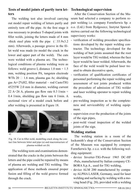
sectional view of a model crack before and<br />
after welding is presented in Figure 18.<br />
a) b)<br />
Fig. 18. Cut in fillet weld, modelling crack along the contact<br />
line between letter and pipe (a) and macrostructure of<br />
plasma-welded cut (b)<br />
The welding tests and examinations demonstrated<br />
that the cracks in the joints between the<br />
letters and the pipe could be repaired by means<br />
of plasma arc welding and TIG welding. The<br />
application of these methods ensured proper<br />
fusion and filling of the weld groove formed<br />
through the crack.<br />
Technological supervision<br />
After the Conservation Section of the Museum<br />
had selected a company to perform repair<br />
welding i.e. company FormSerwis Sp. z<br />
o.o. (Ltd.) from Bydgoszcz, Instytut <strong>Spawalnictwa</strong><br />
carried out the following technological<br />
supervisory works:<br />
- verification of welding procedure specifications<br />
developed by the repair welding contractor.<br />
The technology developed for the<br />
welding of butt joints assumed that the root<br />
layer would be TIG welded, whereas the face<br />
layer would be laser welded. Afterwards, the<br />
face of the weld would be pulsed laser treated<br />
to obtain decorative spots,<br />
- verification of qualification certificates of<br />
personnel performing the repair welding and<br />
assessment of test joints produced within<br />
the procedure of admission of TIG welder<br />
and laser welding operator to repair welding<br />
works,<br />
- pre-welding inspection as to the completeness<br />
and serviceability of welding equipment.<br />
- supervision over the production of the joints<br />
of the sign pipes,<br />
- post-weld visual inspection of the welded<br />
joints of the sign.<br />
Welding station<br />
The welding station in a room of the<br />
locksmith’s shop of the Conservation Section<br />
of the Museum was equipped by company<br />
FormSerwis Sp. z o.o. with the following welding<br />
equipment:<br />
- device Inverter-TIG-Power 1965 DC-HF<br />
-Puls, manufactured by Italian company CE-<br />
BORA S.p.A., used for TIG welding,<br />
- device ALM 200 manufactured by company<br />
ALPHA LASER, Germany, used for laser<br />
welding and surfacing by welding with a moving<br />
head (Fig. 20), provided with a welding<br />
30 BIULETYN INSTYTUTU SPAWALNICTWA<br />
NR <strong>01</strong>/2<strong>01</strong>2