PORTABLE Srvm3-20120822 - Gillette Generators
PORTABLE Srvm3-20120822 - Gillette Generators
PORTABLE Srvm3-20120822 - Gillette Generators

Create successful ePaper yourself
Turn your PDF publications into a flip-book with our unique Google optimized e-Paper software.
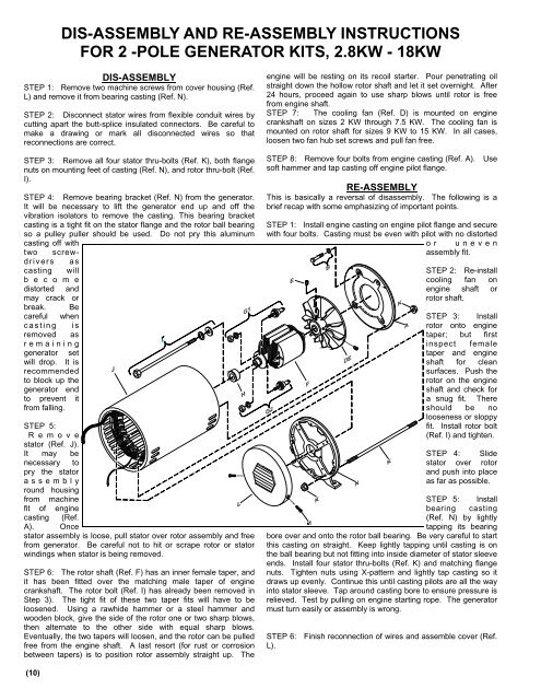
DIS-ASSEMBLY AND RE-ASSEMBLY INSTRUCTIONS<br />
FOR 2 -POLE GENERATOR KITS, 2.8KW - 18KW<br />
DIS-ASSEMBLY<br />
STEP 1: Remove two machine screws from cover housing (Ref.<br />
L) and remove it from bearing casting (Ref. N).<br />
STEP 2: Disconnect stator wires from flexible conduit wires by<br />
cutting apart the butt-splice insulated connectors. Be careful to<br />
make a drawing or mark all disconnected wires so that<br />
reconnections are correct.<br />
STEP 3: Remove all four stator thru-bolts (Ref. K), both flange<br />
nuts on mounting feet of casting (Ref. N), and rotor thru-bolt (Ref.<br />
I).<br />
STEP 4: Remove bearing bracket (Ref. N) from the generator.<br />
It will be necessary to lift the generator end up and off the<br />
vibration isolators to remove the casting. This bearing bracket<br />
casting is a tight fit on the stator flange and the rotor ball bearing<br />
so a pulley puller should be used. Do not pry this aluminum<br />
casting off with<br />
two screwdrivers<br />
as<br />
casting will<br />
b e c o m e<br />
distorted and<br />
may crack or<br />
break. Be<br />
careful when<br />
casting is<br />
removed as<br />
remaining<br />
generator set<br />
will drop. It is<br />
recommended<br />
to block up the<br />
generator end<br />
to prevent it<br />
from falling.<br />
STEP 5:<br />
R e m o v e<br />
stator (Ref. J).<br />
It may be<br />
necessary to<br />
pry the stator<br />
assembly<br />
round housing<br />
from machine<br />
fit of engine<br />
casting (Ref.<br />
A). Once<br />
stator assembly is loose, pull stator over rotor assembly and free<br />
from generator. Be careful not to hit or scrape rotor or stator<br />
windings when stator is being removed.<br />
STEP 6: The rotor shaft (Ref. F) has an inner female taper, and<br />
it has been fitted over the matching male taper of engine<br />
crankshaft. The rotor bolt (Ref. I) has already been removed in<br />
Step 3). The tight fit of these two taper fits will have to be<br />
loosened. Using a rawhide hammer or a steel hammer and<br />
wooden block, give the side of the rotor one or two sharp blows,<br />
then alternate to the other side with equal sharp blows.<br />
Eventually, the two tapers will loosen, and the rotor can be pulled<br />
free from the engine shaft. A last resort (for rust or corrosion<br />
between tapers) is to position rotor assembly straight up. The<br />
engine will be resting on its recoil starter. Pour penetrating oil<br />
straight down the hollow rotor shaft and let it set overnight. After<br />
24 hours, proceed again to use sharp blows until rotor is free<br />
from engine shaft.<br />
STEP 7: The cooling fan (Ref. D) is mounted on engine<br />
crankshaft on sizes 2 KW through 7.5 KW. The cooling fan is<br />
mounted on rotor shaft for sizes 9 KW to 15 KW. In all cases,<br />
loosen two fan hub set screws and pull fan free.<br />
STEP 8: Remove four bolts from engine casting (Ref. A). Use<br />
soft hammer and tap casting off engine pilot flange.<br />
RE-ASSEMBLY<br />
This is basically a reversal of disassembly. The following is a<br />
brief recap with some emphasizing of important points.<br />
STEP 1: Install engine casting on engine pilot flange and secure<br />
with four bolts. Casting must be even with pilot with no distorted<br />
or uneven<br />
assembly fit.<br />
STEP 2: Re-install<br />
cooling fan on<br />
engine shaft or<br />
rotor shaft.<br />
STEP 3: Install<br />
rotor onto engine<br />
taper; but first<br />
inspect female<br />
taper and engine<br />
shaft for clean<br />
surfaces. Push the<br />
rotor on the engine<br />
shaft and check for<br />
a snug fit. There<br />
should be no<br />
looseness or sloppy<br />
fit. Install rotor bolt<br />
(Ref. I) and tighten.<br />
STEP 4: Slide<br />
stator over rotor<br />
and push into place<br />
as far as possible.<br />
STEP 5: Install<br />
bearing casting<br />
(Ref. N) by lightly<br />
tapping its bearing<br />
bore over and onto the rotor ball bearing. Be very careful to start<br />
this casting on straight. Keep lightly tapping until casting is on<br />
the ball bearing but not fitting into inside diameter of stator sleeve<br />
ends. Install four stator thru-bolts (Ref. K) and matching flange<br />
nuts. Tighten nuts using X-pattern and lightly tap casting so it<br />
draws up evenly. Continue this until casting pilots are all the way<br />
into stator sleeve. Tap around casting bore to ensure pressure is<br />
relieved. Test by pulling on engine starting rope. The generator<br />
must turn easily or assembly is wrong.<br />
STEP 6: Finish reconnection of wires and assemble cover (Ref.<br />
L).<br />
(10)