PORTABLE Srvm3-20120822 - Gillette Generators
PORTABLE Srvm3-20120822 - Gillette Generators
PORTABLE Srvm3-20120822 - Gillette Generators

Create successful ePaper yourself
Turn your PDF publications into a flip-book with our unique Google optimized e-Paper software.
DESCRIPTION OF A-C GENERATOR OPERATION<br />
A-C GENERATOR<br />
The A-C generator converts the mechanical energy from<br />
the engine to electrical power. There are four major<br />
components involved in the brushless "Power-Assist"<br />
generator set. The construction of each major part is<br />
described in detail.<br />
POWER GENERATION<br />
The rotor windings are initially charged with a D-C voltage<br />
and permanently retains a residual magnetic flux. During<br />
start-up, an initial flow of electric current is induced in the<br />
winding of the capacitor coils (located in the stator). The<br />
lines of magnetic flux, from the charged rotor, are cut by<br />
the stator field coil windings. This induced flow of current<br />
and voltage is very low.<br />
As the engine increases in speed, the voltage induced in<br />
the capacitor windings rises. An alternating current flows<br />
in these windings. The rising and falling magnetic field<br />
from this current is cut by the field coils in the rotor,<br />
inducing an excitation voltage. A diode (rectifier) in the<br />
rotor field winding rectifies the current from A-C to D-C.<br />
The D-C current in the rotor field generates its own<br />
magnetic field which sweeps past the main power<br />
windings in the stator. This sweeping magnetic field<br />
induces the rated voltage in the main winding as long as<br />
the rotor is turning at the correct speed.<br />
When the electric load is connected to the main power<br />
winding, the capacitor coil circuit will tend to prevent the<br />
main winding voltage from falling; therefore, acting as a<br />
capacitor regulator.<br />
This innovative voltage stabilizing effect is called "Power-<br />
Assist" and is an exclusive design with these products.<br />
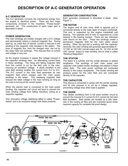
GENERATOR CONSTRUCTION<br />
Each generator component is described in detail. (See<br />
Figure 1)<br />
THE ROTOR<br />
The engine end of rotor inner shaft is tapered and is<br />
connected directly to the male taper of engine crankshaft.<br />
This end is supported by the engine crankshaft ball<br />
bearing. The opposite end of rotor is supported by a ball<br />
bearing in the bearing bracket. There are two individual<br />
coils wound on the rotor. These two windings create a<br />
permanent magnetic field for the main stator power<br />
winding. When the gen-set is working with the capacitor<br />
removed, this rotor winding will generate approximately 8 -<br />
12 VAC at 120 VAC normal output and 16 - 24 VAC at 240<br />
VAC normal output in main winding, due to what is called<br />
“Residual Magnetism”.<br />
THE STATOR<br />
The stator is a cylinder and the inside diameter is slotted<br />
lengthwise. The windings of both main power and<br />
capacitor coils (called exciter windings) are placed in these<br />
stator slots. The main power windings are connected<br />
directly to the output receptacles. The exciter winding will<br />
produce power for the rotor field and are connected<br />
directly to the capacitor.<br />
THE CAPACITOR<br />
This device is connected in series with the exciter winding,<br />
and its only purpose is to act as a voltage regulator,<br />
preventing voltage drop when load is applied.<br />
THE DIODE<br />
Two diodes (rectifiers) form a full wave rectifier circuit to<br />
convert the induced A-C current to D-C current for full rotor<br />
field excitation. Both diodes are located on a disc heatsink<br />
in the cooling air flow and are oversized seven times<br />
required capacity for complete fail-proof design.<br />
FIGURE 1<br />
(4)