PORTABLE Srvm3-20120822 - Gillette Generators
PORTABLE Srvm3-20120822 - Gillette Generators
PORTABLE Srvm3-20120822 - Gillette Generators

You also want an ePaper? Increase the reach of your titles
YUMPU automatically turns print PDFs into web optimized ePapers that Google loves.
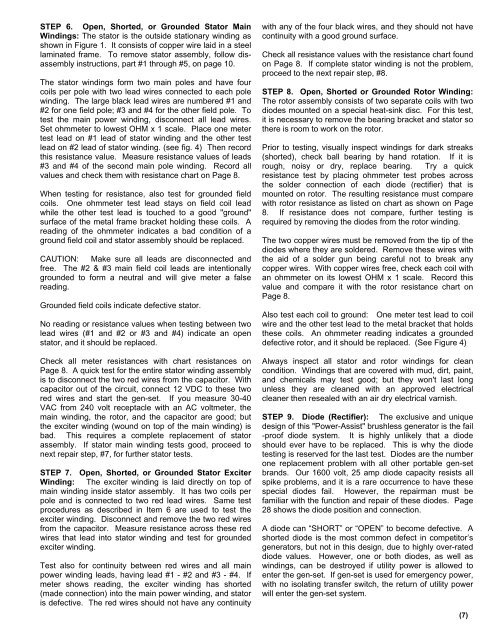
STEP 6. Open, Shorted, or Grounded Stator Main<br />
Windings: The stator is the outside stationary winding as<br />
shown in Figure 1. It consists of copper wire laid in a steel<br />
laminated frame. To remove stator assembly, follow disassembly<br />
instructions, part #1 through #5, on page 10.<br />
The stator windings form two main poles and have four<br />
coils per pole with two lead wires connected to each pole<br />
winding. The large black lead wires are numbered #1 and<br />
#2 for one field pole; #3 and #4 for the other field pole. To<br />
test the main power winding, disconnect all lead wires.<br />
Set ohmmeter to lowest OHM x 1 scale. Place one meter<br />
test lead on #1 lead of stator winding and the other test<br />
lead on #2 lead of stator winding. (see fig. 4) Then record<br />
this resistance value. Measure resistance values of leads<br />
#3 and #4 of the second main pole winding. Record all<br />
values and check them with resistance chart on Page 8.<br />
When testing for resistance, also test for grounded field<br />
coils. One ohmmeter test lead stays on field coil lead<br />
while the other test lead is touched to a good "ground"<br />
surface of the metal frame bracket holding these coils. A<br />
reading of the ohmmeter indicates a bad condition of a<br />
ground field coil and stator assembly should be replaced.<br />
CAUTION: Make sure all leads are disconnected and<br />
free. The #2 & #3 main field coil leads are intentionally<br />
grounded to form a neutral and will give meter a false<br />
reading.<br />
Grounded field coils indicate defective stator.<br />
No reading or resistance values when testing between two<br />
lead wires (#1 and #2 or #3 and #4) indicate an open<br />
stator, and it should be replaced.<br />
Check all meter resistances with chart resistances on<br />
Page 8. A quick test for the entire stator winding assembly<br />
is to disconnect the two red wires from the capacitor. With<br />
capacitor out of the circuit, connect 12 VDC to these two<br />
red wires and start the gen-set. If you measure 30-40<br />
VAC from 240 volt receptacle with an AC voltmeter, the<br />
main winding, the rotor, and the capacitor are good; but<br />
the exciter winding (wound on top of the main winding) is<br />
bad. This requires a complete replacement of stator<br />
assembly. If stator main winding tests good, proceed to<br />
next repair step, #7, for further stator tests.<br />
STEP 7. Open, Shorted, or Grounded Stator Exciter<br />
Winding: The exciter winding is laid directly on top of<br />
main winding inside stator assembly. It has two coils per<br />
pole and is connected to two red lead wires. Same test<br />
procedures as described in Item 6 are used to test the<br />
exciter winding. Disconnect and remove the two red wires<br />
from the capacitor. Measure resistance across these red<br />
wires that lead into stator winding and test for grounded<br />
exciter winding.<br />
Test also for continuity between red wires and all main<br />
power winding leads, having lead #1 - #2 and #3 - #4. If<br />
meter shows reading, the exciter winding has shorted<br />
(made connection) into the main power winding, and stator<br />
is defective. The red wires should not have any continuity<br />
with any of the four black wires, and they should not have<br />
continuity with a good ground surface.<br />
Check all resistance values with the resistance chart found<br />
on Page 8. If complete stator winding is not the problem,<br />
proceed to the next repair step, #8.<br />
STEP 8. Open, Shorted or Grounded Rotor Winding:<br />
The rotor assembly consists of two separate coils with two<br />
diodes mounted on a special heat-sink disc. For this test,<br />
it is necessary to remove the bearing bracket and stator so<br />
there is room to work on the rotor.<br />
Prior to testing, visually inspect windings for dark streaks<br />
(shorted), check ball bearing by hand rotation. If it is<br />
rough, noisy or dry, replace bearing. Try a quick<br />
resistance test by placing ohmmeter test probes across<br />
the solder connection of each diode (rectifier) that is<br />
mounted on rotor. The resulting resistance must compare<br />
with rotor resistance as listed on chart as shown on Page<br />
8. If resistance does not compare, further testing is<br />
required by removing the diodes from the rotor winding.<br />
The two copper wires must be removed from the tip of the<br />
diodes where they are soldered. Remove these wires with<br />
the aid of a solder gun being careful not to break any<br />
copper wires. With copper wires free, check each coil with<br />
an ohmmeter on its lowest OHM x 1 scale. Record this<br />
value and compare it with the rotor resistance chart on<br />
Page 8.<br />
Also test each coil to ground: One meter test lead to coil<br />
wire and the other test lead to the metal bracket that holds<br />
these coils. An ohmmeter reading indicates a grounded<br />
defective rotor, and it should be replaced. (See Figure 4)<br />
Always inspect all stator and rotor windings for clean<br />
condition. Windings that are covered with mud, dirt, paint,<br />
and chemicals may test good; but they won't last long<br />
unless they are cleaned with an approved electrical<br />
cleaner then resealed with an air dry electrical varnish.<br />
STEP 9. Diode (Rectifier): The exclusive and unique<br />
design of this "Power-Assist" brushless generator is the fail<br />
-proof diode system. It is highly unlikely that a diode<br />
should ever have to be replaced. This is why the diode<br />
testing is reserved for the last test. Diodes are the number<br />
one replacement problem with all other portable gen-set<br />
brands. Our 1600 volt, 25 amp diode capacity resists all<br />
spike problems, and it is a rare occurrence to have these<br />
special diodes fail. However, the repairman must be<br />
familiar with the function and repair of these diodes. Page<br />
28 shows the diode position and connection.<br />
A diode can “SHORT” or “OPEN” to become defective. A<br />
shorted diode is the most common defect in competitor’s<br />
generators, but not in this design, due to highly over-rated<br />
diode values. However, one or both diodes, as well as<br />
windings, can be destroyed if utility power is allowed to<br />
enter the gen-set. If gen-set is used for emergency power,<br />
with no isolating transfer switch, the return of utility power<br />
will enter the gen-set system.<br />
(7)