PORTABLE Srvm3-20120822 - Gillette Generators
PORTABLE Srvm3-20120822 - Gillette Generators
PORTABLE Srvm3-20120822 - Gillette Generators

You also want an ePaper? Increase the reach of your titles
YUMPU automatically turns print PDFs into web optimized ePapers that Google loves.
With the engine stopped, remove the protective plastic<br />
cover from capacitor lead connections. Disconnect both<br />
red capacitor winding leads from the capacitor. Check the<br />
capacitor "charge and discharge" readings using an<br />
ohmmeter on the RX-100 scale. (See Figure 2)<br />
When the ohmmeter leads are placed on the capacitor<br />
terminals, a meter deflection should be seen (charging)<br />
followed by a slow return to infinity (discharging). Reverse<br />
the ohmmeter leads and repeat the procedure for the<br />
same results. No meter deflection or continuing continuity<br />
indicates an open or shorted capacitor.<br />
All capacitors have an internal, built-in circuit breaker. If<br />
capacitor becomes "shorted", this internal circuit breaker<br />
trips open and causes the entire top portion (where<br />
terminals are located) to become extremely convexed or to<br />
push outward. When this happens, the capacitor is bad<br />
and must be replaced.<br />
CAUTION: Inspect connection of red wires to capacitor<br />
terminals. They must be soldered rigidly tight. Repair or<br />
replace any loose or poor connections. If there is no<br />
method to check the capacitor, check the Yellow Pages<br />
and call any electric motor repair shop. They have the<br />
equipment to test capacitors. If the capacitor is<br />
determined not to be the cause, proceed to the next repair<br />
step #4.<br />
lost. As the generator is brushless, the field cannot be<br />
"flashed" in the normal way.<br />
The residual magnetism can sometimes be restored by<br />
connecting a full electric load to the receptacles and then<br />
manually increase engine speed to approximately 4500<br />
RPM for two seconds. This allows the compounding<br />
system to assist the full load circuit with a resulting<br />
increase in the effective residual voltage. This is the quick<br />
method and sometimes it does not work. If residual<br />
magnetism of 4-6 volts is not restored, proceed to actual<br />
"flashing" of the rotor winding.<br />
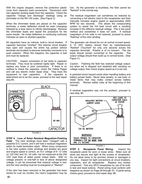
The generator set should be run at normal no-load speed,<br />
A 12 VDC battery should then be instantaneously<br />
"flashed" ("touched" for only one second) across the<br />
capacitor terminals. Polarity is of no concern. The red<br />
leads should remain connected to the capacitor. The<br />
output voltage should then build up to normal levels. (See<br />
Figure 3.)<br />
Caution: Flashing the field has restored voltage output;<br />
but when set is stopped and restarted with resulting no<br />
voltage output, then check engine speed as it is too low.<br />
A potential shock hazard exists when handling battery and<br />
battery jumper leads. Never wear jewelry, or use tools, or<br />
metal items that may make contact across battery<br />
terminals. Review safety rules at the beginning of this<br />
manual.<br />
If residual magnetism was not the problem, proceed to<br />
next step, #5.<br />
FIGURE 2<br />
STEP 4. Loss of Rotor Residual Magnetism-Flashing<br />
Field: The rotor windings have been "charged" with a<br />
powerful D-C current, and it will hold a residual magnetism<br />
within its metal lamination stack. When every component<br />
in the rotor system (rotor windings and diodes) are good<br />
and engine speed is correct, an A-C voltage of 8 -12 volts<br />
on 120 VAC and 16 - 24 volts can be measured at the 240<br />
VAC load lines of stator power output leads. With no<br />
voltage present, or one-half or less of above designated<br />
voltage, it can be presumed that residual voltage is lost,<br />
and the rotor winding must be re-energized or "flashed".<br />
If the rotor has been removed or the generator has been<br />
stored for over six months, the rotor's magnetism may be<br />
(6)<br />
FIGURE 3<br />
STEP 5. Receptacle Panel Wiring: Inspect the<br />
receptacle panel for worn or loose wires. Make sure all<br />
wires are secure and tight at the screws of receptacles.<br />
Do not allow wires to be pinched, kinked or damaged in<br />
any way. Inspect for tight connections at circuit breakers,<br />
capacitors, and all receptacles. Replace any broken<br />
component. Test any GFCI receptacles by use of its builtin<br />
test and reset buttons. Panel wiring must conform with<br />
diagrams as shown on Page 28 through 33. If panel wiring<br />
checks good, proceed to next repair step, #6.