PORTABLE Srvm3-20120822 - Gillette Generators
PORTABLE Srvm3-20120822 - Gillette Generators
PORTABLE Srvm3-20120822 - Gillette Generators

Create successful ePaper yourself
Turn your PDF publications into a flip-book with our unique Google optimized e-Paper software.
If the engine no load speed is normal 3750 RPM but<br />
output voltage is only half the normal volts, one of the two<br />
diodes may be open, It is necessary to determine whether<br />
this voltage is a result of an open diode or is due to a<br />
defective rotor or stator winding. Suspect a defective<br />
capacitor if both diodes and windings are good.<br />
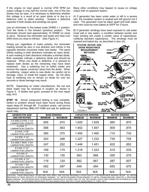
Use an ohmmeter in the lowest scale OHMS x 1 position.<br />
Test the diode in the forward (positive) position. The<br />
ohmmeter should read approximately 15 OHMS (or close<br />
to zero). Reverse the ohmmeter test leads and read over<br />
2000 ohms (or close to infinity). (See Figure 4.)<br />
Simply put, regardless of meter polarity, the ohmmeter<br />
reading should be zero in one direction and infinity in the<br />
opposite direction (reversed meter test leads). The same<br />
infinity reading in both directions indicates an open diode.<br />
A zero reading in both directions indicates a shorted diode.<br />
Both examples indicate a defective diode and should be<br />
replaced. When one diode is defective, it is advised to<br />
replace both diodes as the remaining may have been<br />
weakened. Use a soldering iron to soften solder and<br />
remove the copper conductor wires from the diode. When<br />
re-soldering copper wires to new diode, be careful not to<br />
damage, crack, or break the copper wires. Do not allow<br />
heat of soldering iron to remain on diode for over ten<br />
seconds or diode damage may result.<br />
Many other conditions may happen to cause no voltage<br />
output with no apparent reason:<br />
A) If generator has been under water or left in a severe<br />
rain, the insulation system is soaked and will ground out if<br />
used. The generator must be taken apart and both stator<br />
and rotor must be oven baked at 300ºF for 3 hours.<br />
B) If generator windings have been exposed to salt water<br />
(road salt or sea water), a condition between exciter and<br />
main winding will create a certain value of capacitance,<br />
nullifying standard capacitance. The windings must be<br />
cleaned and baked dry, as described in item (A).<br />
STATOR, ROTOR, AND<br />
DIODE RESISTANCE<br />
MEASUREMENT<br />
METHODS<br />
NOTE: Depending on meter manufacturer, the red and<br />
black leads may be reversed in location as shown in<br />
Figure 4. If diodes test good, proceed to the next repair<br />
step, #10.<br />
STEP 10. Actual component testing is now complete.<br />
Defect or problem should have been found during these<br />
repair steps #1 through #9. If problem exists, call service<br />
department toll-free (866) 537-4388 and ask for additional<br />
repair help.<br />
GENERATOR SIZE MAIN WINDING CAPACITOR WINDING ROTOR WINDING<br />
AND KW RATING MINIMUM MAXIMUM MINIMUM MAXIMUM MINIMUM MAXIMUM<br />
2.8 AND 3.0 KW, 2 1/2<br />
LAMINATION LENGTH .905 .915 1.625 1.635 .850 .870<br />
4.0 KW, 3”<br />
LAMINATION LENGTH .568 .563 1.942 1.947 .905 .875<br />
5.0 KW, 3 7/8”<br />
LAMINATION LENGTH .365 .370 1.455 1.460 .710 .730<br />
6.0 KW, 4 1/4<br />
LAMINATION LENGTH .343 .348 1.227 1.232 .735 .755<br />
6.5 AND 7.5KW, 4 3/4<br />
LAMINATION LENGTH .247 .252 1.446 1.451 .832 .852<br />
9.0 KW, 5 1/2”<br />
LAMINATION LENGTH .169 .174 1.218 1.223 .515 .535<br />
10.5 KW, 6”<br />
LAMINATION LENGTH .130 .135 .563 .568 .555 .575<br />
12.0 KW, 6 1/2”<br />
LAMINATION LENGTH .119 .124 .562 .567 .587 .607<br />
15.0 KW 7 3/4”<br />
LAMINATION LENGTH .092 .097 .449 .454 .655 .675<br />
18.0 KW 10”<br />
LAMINATION LENGTH N/A N/A N/A N/A N/A N/A<br />
CAUTION: THESE RESISTANCE VALUES ARE VERY SMALL AND TESTING REQUIRES A GOOD QUALITY LOW RESISTANCE READING METER. ALL METER<br />
READINGS OF ZERO INDICATE AN OPEN(BAD) WINDING. ALL METER READINGS FROM WINDING TO METAL FRAME(GROUND), INDICATE A GROUNDED<br />
(BAD) WINDING. ROTOR RESISTANCE IS MEASURED ACROSS EACH SOLDER JOINT OF THE TWO DIODES, WHICH ARE CONNECTED IN PARRALLEL WITH<br />
ROTOR COILS. TO DETERMINE RESISTANCE OF EACH SINGLE POLE, MULTIPLY CHART RESISTANCE X 4, THEN ÷ BY 2.<br />
(8)<br />
FIGURE 4