PORTABLE Srvm3-20120822 - Gillette Generators
PORTABLE Srvm3-20120822 - Gillette Generators
PORTABLE Srvm3-20120822 - Gillette Generators

You also want an ePaper? Increase the reach of your titles
YUMPU automatically turns print PDFs into web optimized ePapers that Google loves.
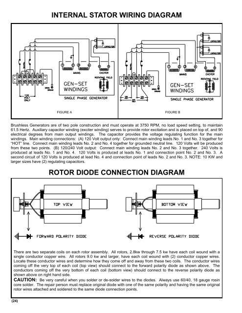
INTERNAL STATOR WIRING DIAGRAM<br />
FIGURE A<br />
FIGURE B<br />
Brushless <strong>Generators</strong> are of two pole construction and must operate at 3750 RPM, no load speed setting, to maintain<br />
61.5 Hertz. Auxiliary capacitor winding (exciter winding) serves to provide rotor excitation and is placed on top of, and 90<br />
electrical degrees from main output windings. The capacitor provides the voltage regulating function for the main<br />
windings. Main winding connections: (A) 120 Volt output only: Connect main winding leads No. 1 and No. 3 together for<br />
“HOT” line. Connect main winding leads No. 2 and No. 4 together for grounded neutral line. 120 Volts will be produced<br />
from these two points. (B) 120/240 Volt output: Connect main winding leads No. 2 and No. 3 together. 240 Volts is<br />
produced at leads No. 1 and No. 4. 120 Volts is produced at leads No. 1 and connection point No. 2 and No. 3. A<br />
second circuit of 120 Volts is produced at lead No. 4 and connection point of leads No. 2 and No. 3. NOTE: 10 KW and<br />
larger sizes have (2) regulating capacitors.<br />
ROTOR DIODE CONNECTION DIAGRAM<br />
There are two separate coils on each rotor assembly. All rotors, 2.8kw through 7.5 kw have each coil wound with a<br />
single conductor copper wire. All rotors 9.0 kw and larger, have each coil wound with (2) conductor copper wires.<br />
Locate these conductor wires and determine how they come off and away from these two coils. The conductor wires<br />
coming off the very top of each coil (top view) should connect to the forward polarity diode as shown above. The<br />
conductors coming off the very bottom of each coil (bottom view) should connect to the reverse polarity diode as<br />
shown above on right hand side.<br />
CAUTION: Be very careful when you solder or de-solder wires to the diodes. Always use 60/40, 18 gauge rosin<br />
core solder. The repair person must replace original diode with one of the same polarity and having the same original<br />
rotor wires attached and soldered to the same diode connection points.<br />
(24)