Jones Vectors and Matrices
Jones Vectors and Matrices
Jones Vectors and Matrices

Create successful ePaper yourself
Turn your PDF publications into a flip-book with our unique Google optimized e-Paper software.
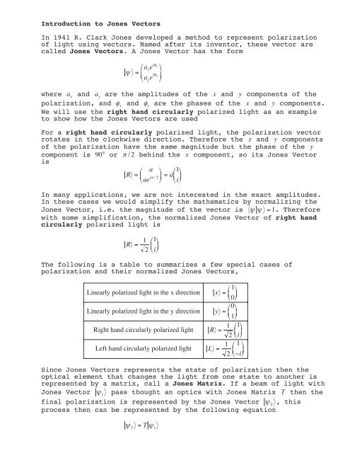
Introduction to <strong>Jones</strong> <strong>Vectors</strong><br />
In 1941 R. Clark <strong>Jones</strong> developed a method to represent polarization<br />
of light using vectors. Named after its inventor, these vector are<br />
called <strong>Jones</strong> <strong>Vectors</strong>. A <strong>Jones</strong> Vector has the form<br />
<br />
<br />
= i x<br />
ae <br />
<br />
x<br />
i y<br />
ae<br />
<br />
y <br />
where a x<br />
<strong>and</strong> a y<br />
are the amplitudes of the x <strong>and</strong> y components of the<br />
polarization, <strong>and</strong> x<br />
<strong>and</strong> y<br />
are the phases of the x <strong>and</strong> y components.<br />
We will use the right h<strong>and</strong> circularly polarized light as an example<br />
to show how the <strong>Jones</strong> <strong>Vectors</strong> are used<br />
For a right h<strong>and</strong> circularly polarized light, the polarization vector<br />
rotates in the clockwise direction. Therefore the x <strong>and</strong> y components<br />
of the polarization have the same magnitude but the phase of the y<br />
component is 90° or /2 behind the x component, so its <strong>Jones</strong> Vector<br />
is<br />
a<br />
R = i<br />
a<br />
<br />
<br />
ae<br />
/2 = 1 i <br />
In many applications, we are not interested in the exact amplitudes.<br />
In these cases we would simplify the mathematics by normalizing the<br />
<strong>Jones</strong> Vector, i.e. the magnitude of the vector is = 1. Therefore<br />
with some simplification, the normalized <strong>Jones</strong> Vector of right h<strong>and</strong><br />
circularly polarized light is<br />
R<br />
=<br />
1 1<br />
2 i <br />
The following is a table to summarizes a few special cases of<br />
polarization <strong>and</strong> their normalized <strong>Jones</strong> <strong>Vectors</strong>,<br />
Linearly polarized light in the x direction<br />
Linearly polarized light in the y direction<br />
Right h<strong>and</strong> circularly polarized light<br />
Left h<strong>and</strong> circularly polarized light<br />
x<br />
y<br />
= 1 0 <br />
= 0 1 <br />
R =<br />
1 1<br />
2 i L =<br />
1 1 <br />
<br />
2 i<br />
Since <strong>Jones</strong> <strong>Vectors</strong> represents the state of polarization then the<br />
optical element that changes the light from one state to another is<br />
represented by a matrix, call a <strong>Jones</strong> Matrix. If a beam of light with<br />
<strong>Jones</strong> Vector 1<br />
pass thought an optics with <strong>Jones</strong> Matrix T then the<br />
final polarization is represented by the <strong>Jones</strong> Vector 2<br />
, this<br />
process then can be represented by the following equation<br />
<br />
= T <br />
2 1
If the beam of light passes through a system of optical elements in<br />
the order, T 1<br />
, T 2<br />
,..., T n<br />
, then the equation is<br />
<br />
2<br />
= TT<br />
n n 1......<br />
T11<br />
Notice that in the equation, the order of the matrices is reversed.<br />
In such a system, we can always represent the it by one <strong>Jones</strong> Matrix,<br />
T where<br />
T TT ...... T<br />
=<br />
n n1 1<br />
The following table shows the <strong>Jones</strong> <strong>Matrices</strong> for some of the optical<br />
elements.<br />
Linear polarizer along the x - direction<br />
1 0<br />
<br />
0 0<br />
Linear polarizer along the y - direction<br />
0 0<br />
<br />
0 1<br />
Half - wave plate<br />
1 0 <br />
-<br />
0<br />
e ip