STEELFLEX® - Rexnord
STEELFLEX® - Rexnord
STEELFLEX® - Rexnord

Create successful ePaper yourself
Turn your PDF publications into a flip-book with our unique Google optimized e-Paper software.
T H E F A L K C O R P O R A T I O N<br />
421-110<br />
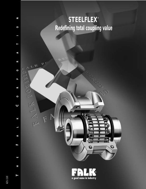
STEELFLEX ®<br />
Redefining total coupling value
FALK STEELFLEX ®<br />
The simplest, most cost-effective coupling<br />
Falk originated the tapered grid design as well as shot peening to<br />
increase fatique strength and torque ratings. Falk Steelflex redefines<br />
total coupling value up to 7.5 million in-lb, 932 000 Nm torque.<br />
Steelflex offers simpler initial installation than gear couplings. The<br />
unique “replace in place” design eliminates the need to move hubs or<br />
re-align shafts, reducing element change-out time. When you look at<br />
the overall savings in initial costs, spare parts costs, and labor costs for<br />
installation, alignment and replacement - plus improved ratings and a<br />
5 Year Heavy-Duty Warranty - it’s easy to see what Falk’s Steelflex Grid<br />
Couplings have over the competition. No other coupling in the torque<br />
range can touch Steelflex for cost-effective performance and reliability.<br />
Extended Maintenance Periods<br />
Now you can install Steelflex and<br />
lubricate it with Falk Long Term<br />
Grease (LTG) and forget periodic,<br />
routine maintenance for five years.<br />
Falk LTG grease was developed<br />
specifically for couplings. It resists the<br />
separation of the oil and thickening<br />
agent that occurs in typical greases.<br />
The initial use of Falk LTG coupling<br />
grease will eliminate routine<br />
lubrication cycles while still providing<br />
the necessary lubrication to the<br />
tapered grid. With LTG, Steellflex<br />
combines the high torque<br />
performance of a gear coupling and<br />
the low maintenance of a disc or<br />
elastomer coupling.<br />
Features that give<br />
Steelflex the lowest lifetime<br />
operating cost<br />
Longer Life<br />
Tapered grids, made of high strength<br />
alloy steel, are quenched and<br />
tempered to spring hardness. The<br />
grid surface is then precision shot<br />
peened to compress the surface<br />
molecules.<br />
The effect is a dramatic increase in<br />
rating, providing reserve strength for<br />
longer life or allowing a smaller size<br />
coupling to be selected. This precision<br />
technology was originally used<br />
in the production of sophisticated<br />
aircraft components.
Quick, Easy Installation…<br />
Replace-In-Place Design<br />
The grid is the wearing member<br />
of a Steelflex coupling and it is a<br />
fraction of the complete coupling<br />
cost. Tapered grids are accessible<br />
through the quickly removable<br />
cover. The replace-in-place design of<br />
the replacement grids allows them<br />
to be dropped in without the need<br />
to remove or reposition hubs or<br />
realign shafts as required with gear<br />
couplings and many elastomer<br />
designs. When coupling-connected<br />
equipment must be moved, the job<br />
takes longer and costs a lot more.<br />
Equipment Protection Against<br />
Shaft Misalignment<br />
The grid is free to rock, pivot and<br />
float within the hub teeth. Generous<br />
misalignment capacity is<br />
provided without<br />
LIGHT LOAD<br />
producing detrimental<br />
bearing side loads created<br />
by other couplings.<br />
HEAVY LOAD<br />
Equipment Protection<br />
Against Shock/<br />
Vibratory Loads<br />
Torsional flexibility is the<br />
ability of Falk Steelflex couplings to<br />
torsionally deflect when subjected to<br />
normal shock or vibratory loads,<br />
providing flexible accommodation to<br />
changing load conditions.<br />
Consequently, Steelflex tunes the<br />
drive system. It absorbs impact<br />
energy by spreading it over an<br />
CONTACT INCREASES<br />
ELASTOMER<br />
DISC<br />
GEAR<br />
STEELFLEX<br />
LOW CONTACT<br />
I I I I I I I I I<br />
0 1,000 2,000 3,000 4,000 5,000 6,000 7,000 8,000<br />
PIVOTS<br />
FLOATS<br />
ROCKS<br />
increment of time. It damps vibration<br />
and reduces peak or shock loads<br />
by as much as 30%. It is a true shock<br />
absorber for rotary motion, relying<br />
on the predictable resilience of the<br />
steel grid for torsional flexibility.<br />
Coupling Lifetime Operating Costs<br />
150 HP (112 KW) @ 68 RPM<br />
$2,895 Total<br />
$2,390 Total<br />
$5,264 Total<br />
$7,717 Total<br />
U.S. Dollars @ Suggested Consumer<br />
Production losses are not included in this chart.<br />
Initial Costs Labor Costs to Install & Align<br />
Spare Parts Costs Replacement Labor Costs<br />
Versatile Designs<br />
Two cover designs are available in<br />
the popular sizes. Standard spacer,<br />
piloted, high speed, brakewheel or<br />
disc, and controlled torque designs<br />
are also available.<br />
Worldwide Availability<br />
Steelflex couplings and component<br />
parts, are available in popular sizes<br />
and types, in both inch or metric.<br />
Our distribution centers and worldwide<br />
distribution network offer the<br />
largest stock of rough bore, finish<br />
straight bore and Taper-lock bushed<br />
hubs of any shaft coupling on the<br />
market. Plus, Steelflex grid couplings<br />
are warranted for 5 Years when<br />
lubricated with Falk LTG Long Term<br />
Grease.
STEELFLEX Selection Guide
Selection Guide M421-110, August 2003<br />
Table of Contents<br />
How to Select . . . . . . . . . . . . . . . . . . . . . . . 7-9<br />
Service Factors . . . . . . . . . . . . . . . . . . . . . . . 10<br />
How to Order. . . . . . . . . . . . . . . . . . . . . . . . 11<br />
T Type Steelflex Grid Couplings:<br />
Dimensions & Specifications<br />
Type T10 Close Coupled. . . . . . . . . . . . . . . . . . 12<br />
Type T20 Close Coupled . . . . . . . . . . . . . . . . . . 13<br />
Type T31 Full Spacer . . . . . . . . . . . . . . . . . . 14-15<br />
Type T35 Half Spacer . . . . . . . . . . . . . . . . . . 16-17<br />
Type T41 & LT Controlled Torque Coupling . . . . . . . . . 18<br />
Type T44 Controlled Torque Clutches . . . . . . . . . . . . 19<br />
Type T45 & T42 Piloted Controlled Torque Assemblies . . . . 20<br />
Optional Automatic Proximity Sensor Cutout Switch . . . . . 21<br />
Slip Torque Performance Charts . . . . . . . . . . . . . 22-25<br />
Type T50 Floating Shaft Assembly . . . . . . . . . . . . . . 26<br />
Type T50 Floating Shaft Selections . . . . . . . . . . . . . 27<br />
Type T63 Disc Brake . . . . . . . . . . . . . . . . . . . 28-29<br />
Type T70 High Speed . . . . . . . . . . . . . . . . . . . . 30<br />
Type T90 Flywheel. . . . . . . . . . . . . . . . . . . . . . 31<br />
Type T10/G82 Spacer. . . . . . . . . . . . . . . . . . . . 32<br />
Engineering Data<br />
Recommended Commercial Keys – Metric and Inch . . . . . 33<br />
Shaft Diameters & Ratings for 50 Hertz Metric Motors<br />
& NEMA 60 Hertz. . . . . . . . . . . . . . . . . . . . . . 33<br />
Bore Ranges With Square & Rectangular Keys . . . . . . 34-35<br />
Taper Lock Bushings for Type T Hubs & Shaft Hubs . . . . . . 36<br />
WR 2 Values . . . . . . . . . . . . . . . . . . . . . . . . 37<br />
Misalignment Capacities . . . . . . . . . . . . . . . . . . 37<br />
Standard AISE AC & DC Mill Motor Coupling Selections . . . 38<br />
Taper and Counter Bore Limitations . . . . . . . . . . . . . 39<br />
Puller Bolt Holes . . . . . . . . . . . . . . . . . . . . . . 39<br />
Recommended Bores – Metric and Inch . . . . . . . . . 40-42<br />
Coupling Application Data Sheet . . . . . . . . . . . . . . 43<br />
Headquarters & Global Sales Offices . . . . . . . . . . . . 44<br />
Falk Factory Warranty We’re so confident in the performance<br />
and reliability of our latest generation of Falk heavy-duty products<br />
that we’re backing this comprehensive offering with the best<br />
standard warranty in the business. Our full, 3-year Heavy-Duty<br />
Warranty provides “shaft-to-shaft” protection on all Falk<br />
components – including bearings and seals. It’s an industry first...<br />
and one more powerful reason why Falk is your ultimate<br />
bottom-line drive and coupling value. Steelflex grid couplings<br />
are warranted for 5 Years when lubricated with Falk LTG Long<br />
Term Grease.<br />
All Falk Steelflex Couplings Possess the<br />
Following Benefits<br />
High Ratings<br />
Extended Maintenance Periods<br />
Quick Installation<br />
Easy Maintenance<br />
Versatile Design<br />
Availability<br />
Protection Against Shaft Misalignment<br />
Protection Against Shock Loads, Vibration and Thrust<br />
Loads<br />
General Information<br />
– Falk standards apply unless otherwise specified.<br />
– All Dimensions are for reference only and are subject to<br />
change without notice unless certified.<br />
– Unless otherwise specified, Falk coupling hubs will be bored<br />
for CLEARANCE FIT with a setscrew OVER the keyway or<br />
INTERFERENCE FIT without a setscrew.<br />
– Torque ratings of couplings utilizing Taper-Lock bushings can<br />
differ from those that do not. Refer to Falk for details.<br />
– If Falk is to supply coupling hubs bored for Taper-Lock<br />
bushings, the bushing manufacturer MUST be noted on the<br />
order.<br />
– Consult Falk when limited end float is required.<br />
Reference Notes<br />
† Peak torque capacity is two times the published rating. Torque<br />
ratings for hubs with bushings differ from those shown, refer to<br />
Table 17, Page 36.<br />
‡ Consult Falk for higher speeds.<br />
Maximum bores are reduced for hubs furnished with an<br />
INTERFERENCE FIT and a setscrew OVER the keyway. Refer to<br />
Falk for details. Recommended key sizes for the listed<br />
maximum bores are shown in Table 11 on Page 33.<br />
Minimum bore is the smallest bore to which a RSB hub (rough<br />
stock bore) hub can be bored. Depending upon coupling<br />
size, rough stock bore hubs may have only a blind centering<br />
hole or a through hole that will permit remachining of the<br />
hubs to the minimum bores specified.<br />
Warranty extends for 3 years from date of shipment. Does not apply to Falk<br />
Omnibox, Ultramite, Fluid Couplings, Renew and spare parts. Warranty applies to<br />
Steelflex and Lifelign couplings with the use of Falk Long Term grease.<br />
Copyright 2003. The Falk Corporation. All Rights Reserved. Litho in U.S.A.<br />
FALK, STEELFLEX, and “a good name in industry” are registered trademarks.<br />
Dodge is a registered trademark.<br />
Taper-Lock is a registered trademark of a bushing under license.<br />
The contents of this selection guide are subject to change without notice or obligation.<br />
Information contained herein should be confirmed before placing orders.<br />
© The Falk Corporation, 2003 (M421-110) 5
F A L K<br />
Falk Steelflex Grid Couplings<br />
A general purpose, lubricated design that combines the economy and high torque capacity of a gear coupling with the torsional flexibility<br />
of an elastomer coupling. Backed by a 5–year lubrication warranty, Falk Steelflex couplings require no periodic maintenance when<br />
lubricated with Falk LTG (Long Term Grease) at installation. Featuring 25 sizes, Stelflex couplings can accommodate torque loads of<br />
932 000 (Nm) and shaft diameters of 508 millimeters.<br />
A double flexing, close-coupled<br />
design for use in four bearing<br />
systems. Features a horizontally split<br />
cover which allows for grid<br />
replacement without the movement of<br />
the connected equipment.<br />
(See Page 12.)<br />
Type T10 Close Coupled<br />
Type T50 Piloted<br />
For use on line shaft applications. Can<br />
be used in place of single engagement<br />
gear couplings to provide torsional<br />
resiliency and lower overall operating<br />
cost.<br />
(See Pages 26 & 27.)<br />
A double flexing design featuring a<br />
vertically split steel cover. Ideal for<br />
higher running speeds. (See Page 13.)<br />
Proven to be far superior to<br />
drum-type brakes in cost,<br />
construction and performance.<br />
(See Pages 28 & 29.)<br />
Type T20 Close Coupled<br />
Type T63 Disc Brake<br />
Complete center section drops<br />
out for easy service of connected<br />
equipment bearings and seals.<br />
Ideal for pump applications.<br />
(See Pages 14 & 15.)<br />
Designed for operating speeds beyond<br />
those of the T10 and T20 designs.<br />
Features a one-piece cover and<br />
balanced components. (See Page 30.)<br />
Type T31 Full Spacer<br />
Type T70 High Speed<br />
An economical spacer design<br />
for easy service of connected<br />
equipment bearings and<br />
seals. Ideal for pump<br />
applications. (See Pages 16 &<br />
17.)<br />
Used primarily to connect the<br />
flywheel of an engine to the<br />
driven machinery. It provides for<br />
higher torque ratings with<br />
resulting smaller sizes and lower<br />
costs than elastomer couplings.<br />
(See Page 31.)<br />
Type T35 Half Spacer<br />
Type T90 Flywheel<br />
Provides adjustable slipping action to<br />
protect connected equipment from<br />
shock, jams, or temporary overloads.<br />
(See Pages 18 thru 25.)<br />
Type T41, T42, T44 & T45 Controlled Torque<br />
Type T10/G82 Spacer<br />
A combination of two<br />
standard Falk couplings.<br />
Utilizes readily available<br />
components for an<br />
economical price and<br />
shorter lead time than<br />
T31/T35 couplings.<br />
(See Page 32.)<br />
Type T50 Floating Shaft<br />
Double piloted design<br />
for connecting<br />
equipment where the<br />
distance between shafts<br />
is too large for a<br />
spacer type coupling.<br />
(See Pages 26 & 27.)<br />
Type BW Brakewheel<br />
Provides a built-in braking surface right at or<br />
near the centerline of the coupling ...saves<br />
space and dollars. (See Selection Guide<br />
431-310.)<br />
WARNING! Mixing grid coupling components from different manufacturers may cause premature<br />
failure and possible personal injury or property damage from flying debris.<br />
6 (M421-110) © The Falk Corporation, 2003
How to Select<br />
Standard Selection Method (except T41/T44 &T63)<br />
The standard selection method can be used for most motor,<br />
turbine, or engine driven applications. The following<br />
information is required to select a flexible coupling:<br />
Kilowatt (kW) or torque<br />
Running rpm<br />
Application or type of equipment to be connected (motor to<br />
pump, gear drive to conveyor, etc.)<br />
Shaft diameters<br />
Shaft gaps<br />
Physical space limitations<br />
Special bore or finish information and type of fit<br />
Exceptions are High Peak Loads and Brake Applications. For<br />
these conditions use the Formula Selection Method in the<br />
next column, or consult your local Falk Representative for<br />
assistance.<br />
1. RATING: Determine system torque. If torque is not given,<br />
calculate as shown below:<br />
kW x 9549<br />
System Torque (Nm) =<br />
rpm<br />
Where kilowatt (kW) is the actual or transmitted power required<br />
by the application (if unknown, use the motor or turbine<br />
nameplate rating) and rpm is the actual speed the coupling is<br />
rotating. Applications that require rapid changes in direction or<br />
torque reversals should be referred to Falk Engineering.<br />
2. SERVICE FACTOR: Determine appropriate service factor from<br />
Table 2, Page 10.<br />
3. REQUIRED MINIMUM COUPLING RATING: Determine the<br />
required minimum coupling rating as shown below:<br />
Minimum Coupling Rating = S.F. (Service Factor) x Torque (Nm)<br />
4. TYPE: Refer to Page 6 and select the appropriate coupling<br />
type.<br />
5. SIZE: Turn to appropriate pages for the coupling type chosen<br />
and trace down the torque column to a value that is equal or<br />
greater than that determined in Step 3 above. The coupling<br />
size is shown in the first column.<br />
6. CHECK: Check speed (rpm), bore, gap, and dimensions.<br />
STANDARD SELECTION EXAMPLE:<br />
Select a coupling to connect a 55 kW, 1500 rpm electric motor<br />
driving a lobe type blower. Motor shaft diameter is 60 mm,<br />
blower shaft diameter is 45 mm. Shaft extensions are 140 mm<br />
and 110 mm. Selection is replacing a gear type coupling with a<br />
3 mm gap.<br />
1. DETERMINE REQUIRED RATING:<br />
55 kW x 9549<br />
System Torque (Nm) = = 350 Nm<br />
1500 rpm<br />
2. SERVICE FACTOR: From Table 2 = 1.25<br />
3. REQUIRED MINIMUM COUPLING RATING:<br />
1.25 x 350 Nm = 438 Nm<br />
4. SIZE: From Page 12 a Size 1070T is the proper selection<br />
based on a torque rating of 904 Nm exceeding the required<br />
minimum coupling rating of 438 Nm.<br />
5. CHECK: Allowable speed capacity of 4125 (1070T10)<br />
exceeds the required speed of 1500 rpm. Maximum bore<br />
capacity of 67 mm exceeds the actual shaft diameters.<br />
Type T63 Static (holding) Brake Applications<br />
1. SIZE: The brake rating must equal or exceed the application<br />
requirements. Determine the required coupling size by<br />
comparing the application loads (from Steps A and B below)<br />
to the coupling brake rating listed on Page 28. Use the<br />
highest torque value calculated to determine the coupling<br />
size.<br />
A. For normal service applications, use the application torque in<br />
Nm.<br />
Transmitted kW x 9549<br />
System Torque (Nm) =<br />
rpm<br />
B. For repetitive high peak load applications, use the system peak<br />
torque in Nm. (Repetitive is defined as more than 1000 times<br />
during the expected coupling life.)<br />
2. CALIPER TORQUE BRAKE RATING: For the coupling size<br />
selected, compare the caliper brake torque rating on Page 29<br />
to the holding torque requirement of the application. Falk<br />
recommends that the caliper torque rating (min.) be at least<br />
two times the holding torque requirement for static<br />
applications to compensate for the possibility of foreign<br />
matter on the disc surfaces, loss of condition of the brake pad<br />
surfaces, or other conditions that may affect the holding<br />
ability of the caliper brake.<br />
Caliper brakes and brake discs listed are designed primarily<br />
for static and/or emergency brake applications. NOTE:<br />
Check brake system and lining wear after emergency stops.<br />
They can, however, also be used for dynamic stopping if only<br />
used occasionally, such as shutting down the equipment for<br />
the day or between shift changes. For stopping high inertia<br />
systems or for applications that require more frequent<br />
stopping, consult your local Falk Representative.<br />
3. CHECK: Check maximum bores, speeds, and dimensions.<br />
Type T63 Stopping Or Service Brake Applications<br />
1. SIZE: The coupling brake rating must equal or exceed the<br />
application requirements. Determine the required coupling<br />
size by comparing the application loads (from Steps A, B and<br />
C below) to the coupling brake rating listed on Page 28. Use<br />
the highest torque value calculated to determine the coupling<br />
size.<br />
A. For the selected caliper brake and disc diameter ,use the<br />
maximum brake torque in Nm.<br />
B. For normal service applications, use the application torque in<br />
Nm.<br />
Transmitted kW x 9549<br />
System Torque (Nm) =<br />
rpm<br />
C. For repetitive high peak load applications, use the system<br />
peak torque in Nm (Repetitive is defined as more than 1000<br />
times during the expected coupling life.)<br />
2. CHECK: Check maximum bores, speeds, and dimensions.<br />
© The Falk Corporation, 2003 (M421-110) 7
F A L K<br />
How to Select<br />
Formula Selection Method (except T41/T44 & T63)<br />
The Standard Selection Method can be used for most coupling<br />
selections. The procedures below should be used for:<br />
High Peak Loads.<br />
Brake Applications (where the brake disc or brake wheel is to<br />
be an integral part of the coupling, consult Falk for design<br />
options).<br />
Providing system peak torque and frequency, duty cycle, and<br />
brake torque rating will allow for a more refined selection using<br />
the Formula Selection Method.<br />
1. HIGH PEAK LOADS: Use one of the following formulas for<br />
applications using motors with torque characteristics that are higher<br />
than normal; applications with intermittent operations, shock<br />
loading, inertia effects due to starting and stopping and or system<br />
induced repetitive high peak torques. System Peak Torque is the<br />
maximum torque that can exist in the system. Select a coupling with<br />
a torque rating equal to or greater than selection torque calculated<br />
below.<br />
A. NON-REVERSING HIGH PEAK TORQUE<br />
Selection Torque (Nm) = System Peak Torque<br />
or<br />
System Peak kW x 9549<br />
Selection Torque (Nm) =<br />
rpm<br />
B. REVERSING HIGH PEAK TORQUE<br />
Selection Torque (Nm) =2xSystem Peak Torque<br />
or<br />
2 x Peak kW x 9549<br />
Selection Torque (Nm) =<br />
rpm<br />
C. OCCASIONAL PEAK TORQUES (Non-Reversing) If a system<br />
peak torque occurs less than 1000 times during the expected<br />
coupling life, use the following formula:<br />
Selection Torque (Nm) = 0,5 x System Peak Torque<br />
or<br />
0,5 x Peak kW x 9549<br />
Selection Torque (Nm) =<br />
rpm<br />
For reversing service select per step B.<br />
2. BRAKE APPLICATIONS: If the torque rating of the brake<br />
exceeds the motor torque use the brake rating as follows:<br />
Selection Torque (Nm) = Brake Torque Rating x S.F.<br />
FORMULA SELECTION EXAMPLE — High Peak Load:<br />
Select a coupling for reversing service to connect a gear drive low<br />
speed shaft to a runout mill table roll. The electric motor rating is 37<br />
kW at the base speed and the system peak torque at the coupling is<br />
estimated to be 17 000 Nm. Coupling speed is 77 rpm at the motor<br />
base speed. The drive shaft diameter is 100 mm with a keyway of<br />
28 mm x 16 mm. The runout table roll diameter is 135 mm with a<br />
keyway of 36 mm x 20 mm. Maximum shaft gap (BE) is 180 mm<br />
long.<br />
1. TYPE: Refer to Page 6 and select the appropriate coupling type.<br />
2. REQUIRED MINIMUM COUPLING RATING:<br />
Use the Reversing High Peak Torque formula in Step 1B.<br />
2 x 17 000 = 34 000 = Selection Torque<br />
3. SIZE: From Page 17, Size 1150T35 with a torque rating of<br />
39 800 exceeds the selection torque of 34 000 Nm.<br />
4. CHECK: The 1150T35 has a maximum BE dimension of<br />
187,5 mm; the shaft hub has a maximum bore of 270 mm<br />
with one rectangular key, (Table 14, Page 34 ); the T hub has<br />
a maximum bore of 215 mm (Table 13, Page 34); and the<br />
allowable speed of 1500 rpm and the dimensions on Page 17<br />
meet the requirements.<br />
TABLE 1 — Coupling Ratings & Allowable<br />
Speeds<br />
Coupling<br />
Size<br />
<br />
kW/RPM <br />
Torque<br />
Rating<br />
(Nm) †<br />
T10<br />
Allowable Speeds —rpm ‡<br />
T20 &<br />
T50 <br />
T31, T35 &<br />
T10/G82<br />
1020T 0,005 52 4500 6000 3600 . . .<br />
1030T 0,016 149 4500 6000 3600 10000<br />
1040T 0,026 249 4500 6000 3600 . . .<br />
1050T 0,046 435 4500 6000 3600 9000<br />
1060T 0,072 684 4350 6000 3600 . . .<br />
1070T 0,104 994 4125 5500 3600 8200<br />
1080T 0,215 2 050 3600 4750 3600 7100<br />
1090T 0,39 3 730 3600 4000 3600 6000<br />
1100T 0,657 6 280 2440 3250 2440 4900<br />
1110T 0,976 9 320 2250 3000 2250 4500<br />
1120T 1,43 13 700 2025 2700 2025 4000<br />
1130T 2,08 19 900 1800 2400 1800 3600<br />
1140T 2,99 28 600 1650 2200 1650 3300<br />
1150T 4,16 39 800 1500 2000 1500 . . .<br />
1160T 5,86 55 900 1350 1750 1350 . . .<br />
1170T 7,81 74 600 1225 1600 1225 . . .<br />
1180T 10,8 103 000 1100 1400 1100 . . .<br />
1190T 14,3 137 000 1050 1300 1050 . . .<br />
1200T 19,5 186 000 900 1200 900 . . .<br />
1210T 26 249 000 820 . . . . . . . . .<br />
1220T 35,1 336 000 730 . . . . . . . . .<br />
1230T 45,6 435 000 680 . . . . . . . . .<br />
1240T 58,6 559 000 630 . . . . . . . . .<br />
1250T 78,1 746 000 580 . . . . . . . . .<br />
1260T 97,6 932 000 540 . . . . . . . . .<br />
Refer to Page 5 for General Information and Reference notes.<br />
kW/RPM and torque rating values for hubs with Taper Lock ® bushings differ from<br />
those shown above. Refer to Table 17, Page 36.<br />
Speeds shown above are for single Type T50 couplings; speeds for Type T50<br />
Floating Shaft couplings are shown in Table 10, Page 27.<br />
T70<br />
8 (M421-110) © The Falk Corporation, 2003
How to Select<br />
Type T41 Controlled Torque Couplings & T44<br />
Controlled Torque Clutches<br />
Type T41 Controlled Torque Couplings<br />
1. RUNNING TORQUE: Calculate normal running torque<br />
Required kW x 9549<br />
Running Torque (Nm) =<br />
rpm<br />
2. SLIP TORQUE: Slip torque = Running Torque x 150%<br />
(Overload Setting.) Falk recommends a minimum 150%<br />
overload setting for steady or moderate shock load<br />
applications. For heavy shock load applications, a 200% or<br />
greater overload setting may be required.<br />
3. COUPLING SIZE: Refer to Table 6, Page 18 — Trace down<br />
the Slip Torque column to a figure equal to or in excess of the<br />
calculated slip torque determined in Step 2. Read the coupling<br />
size in the next column.<br />
4. CHECK:<br />
A. Check shaft diameters against coupling maximum bores<br />
shown in Table 6, Page 18. If selection does not have<br />
adequate bore capacity, refer to Table 13, Page 34 or Table<br />
15, Page 35 for maximum bores with square or rectangular<br />
keys, or select the next larger size coupling.<br />
B. Check the required speed against the allowable speed<br />
shown in Table 6, Page 18. If a higher speed is required,<br />
refer application details to the local Falk representative.<br />
C. Check allowable slip torque times from Slip Torque<br />
Performance Charts on Pages 22 through 25. The length of<br />
time a coupling can slip without exceeding its thermal<br />
capacity is a function of the slip torque setting and the<br />
operating speed. An automatic cutout switch, Page 21, can<br />
be provided when damaging thermal conditions exist.<br />
D. Check application dimension requirements against selected<br />
coupling dimensions shown on Page 18.<br />
E. Check usable shaft length to the coupling hub lengths on<br />
Page 18. If necessary, overhang hubs within the limits<br />
specified on Page 21.<br />
SELECTION EXAMPLE:<br />
Select a controlled torque coupling to connect a 15,0 kW, 1500<br />
rpm, 160L frame motor to the high speed shaft of a gear drive<br />
driving a screw feeder. Motor shaft diameter is 42 mm with a<br />
usable shaft length of 110 mm. Drive high speed shaft diameter<br />
is 35 mm with usable shaft length of 65 mm.<br />
1. RUNNING TORQUE: From Step 1 above:<br />
15,0 kW x 9549<br />
Running Torque (Nm) = = 95,5 Nm<br />
1500 RPM<br />
2. SLIP TORQUE: From Step 2 above: Slip Torque = 95,5 Nm x<br />
150% = 143,2 Nm.<br />
3. SIZE: From Table 6, Page 18, the minimum size coupling is the<br />
Size 40T41, which has a maximum slip torque of 167 Nm.<br />
4. CHECK:<br />
A. From Table 6, Page 18, the Size 40T41, T41 hub has a<br />
maximum bore capacity of only 35 mm and the T hub<br />
maximum bore capacity is 43 mm. The preferred mounting<br />
arrangement is to have the T41 hub on the motor (for<br />
optimum cooling during slippage). Therefore, select the size<br />
50T41 with a T41 hub maximum bore capacity of 45 mm,<br />
as compared to the motor shaft diameter of 42mm, and the<br />
slip torque required is within its range.<br />
B. Allowable Speed of 3600 rpm exceeds required 1500 rpm.<br />
C. From Page 22, the Size 50T41 with slip torque setting of<br />
143,2 Nm and running speed of 1500 rpm will permit 27<br />
seconds slip if followed by 9 minutes of non-slip.<br />
D. See Page 18 for dimensions.<br />
E. Usable shaft length of motor is 110 mm and “W”<br />
dimension for T41 hub is 87,4 mm, therefore no overhang<br />
required. Usable shaft length of drive is 65 mm and “C”<br />
dimension of “T” hub is 60,5 mm, therefore no overhang<br />
required.<br />
Type T44 Controlled Torque Clutches<br />
1. RUNNING TORQUE<br />
Required kW x 9549<br />
Running Torque (Nm) = =<br />
rpm<br />
2. SLIP TORQUE: Slip Torque = Running Torque x 150%<br />
(Overload Setting.) Falk recommends a minimum 150%<br />
overload setting for steady or moderate shock load<br />
applications. For heavy shock load applications a 200% or<br />
greater overload setting may be required.<br />
3. CLUTCH SIZE: Refer to Table 7, Page 19 — Trace down the<br />
Slip Torque column to a figure equal to or in excess of the<br />
calculated slip torque determined in Step 2. Read clutch size<br />
in the next column.<br />
A. Check shaft diameters against clutch maximum bores<br />
shown in Table 7. If selection does not have adequate bore<br />
capacity refer to Table 15, Page 35 for maximum bores with<br />
square or rectangular keys, or select the next larger size clutch.<br />
B. Check the required speed against the allowable speed<br />
shown in Table 7. If a higher speed is required, refer<br />
application details to the local Falk representative.<br />
C. Check allowable slip torque times from Slip Torque<br />
Performance Charts on Pages 22 through 25. The length of<br />
time a clutch can slip without exceeding its thermal capacity<br />
is a function of the slip torque setting and the operating<br />
speed. An automatic cutout switch, Page 21, can be<br />
provided when damaging thermal conditions exist.<br />
D. Check application dimension requirements against selected<br />
clutch dimensions shown on Page 19.<br />
E. Check usable shaft length to the clutch hub length on Page<br />
19. If necessary, overhang hub within the limits specified on<br />
Page 21.<br />
© The Falk Corporation, 2003 (M421-110) 9
F A L K<br />
Service Factors<br />
TABLE2—FlexibleCouplingServiceFactors for Motor and Turbine Drives<br />
Service factors listed are typical values based on normal operation of the drive systems.<br />
Alphabetical listing of applications<br />
Alphabetical listing of industries<br />
Service<br />
Factor<br />
AERATOR ..........................................2.0<br />
AGITATORS<br />
Vertical and Horizontal<br />
Screw, Propeller, Paddle ...............1.0<br />
BARGE HAUL PULLER ......................1.5<br />
BLOWERS<br />
Centrifugal ......................................1.0<br />
Lobe or Vane ...................................1.25<br />
CAR DUMPERS .................................2.5<br />
CAR PULLERS....................................1.5<br />
CLARIFIER OR CLASSIFIER ..............1.0<br />
COMPRESSORS<br />
Centrifugal ......................................1.0<br />
Rotary, Lobe or Vane........................1.25<br />
Rotary, Screw ...................................1.0<br />
Reciprocating<br />
Direct Connected ..................Refer to Falk<br />
Without Flywheel ...................Refer to Falk<br />
With Flywheel and Gear<br />
between Compressor<br />
and Prime Mover<br />
1 cylinder, single acting.............3.0<br />
1 cylinder, double acting...........3.0<br />
2 cylinders, single acting ...........3.0<br />
2 cylinders, double acting .........3.0<br />
3 cylinders, single acting ...........3.0<br />
3 cylinders, double acting .........2.0<br />
4 or more cly., single act...........1.75<br />
4 or more cyl., double act. ........1.75<br />
CONVEYORS<br />
Apron, Assembly, Belt, Chain,<br />
Flight, Screw.................................1.0<br />
Bucket .............................................1.25<br />
Live Roll, Shaker and<br />
Reciprocating ...............................3.0<br />
CRANES AND HOIST<br />
Main Hoist................................. 1.75<br />
Skip Hoist....................................1.75<br />
Slope...............................................1.5<br />
Bridge, Travel or Trolley ...................1.75<br />
DYNAMOMETER...............................1.0<br />
ELEVATORS<br />
Bucket, Centrifugal Discharge ..........1.25<br />
Freight or Passenger..........Not Approved<br />
Gravity Discharge ............................1.25<br />
ESCALATORS ................... Not Approved<br />
EXCITER, GENERATOR..................... 1.0<br />
EXTRUDER, PLASTIC......................... 1.5<br />
FANS<br />
Centrifugal ......................................1.0<br />
Cooling Tower .................................2.0<br />
Forced Draft — Across the<br />
Line start ......................................1.5<br />
Forced Draft Motor<br />
Driven thru fluid or<br />
electric slip clutch .........................1.0<br />
Gas Recirculating.............................1.5<br />
Induced Draft with damper<br />
control or blade cleaner................1.25<br />
Induced Draft without controls ..........2.0<br />
FEEDERS<br />
Apron, Belt, Disc, Screw ...................1.0<br />
Reciprocating...................................2.5<br />
GENERATORS<br />
Even Load........................................1.0<br />
Hoist or Railway Service ...................1.5<br />
Service<br />
Factor<br />
Welder Load ....................................2.0<br />
HAMMERMILL ...................................1.75<br />
LAUNDRY WASHER OR<br />
TUMBLER .......................................2.0<br />
LINE SHAFTS<br />
Any Processing Machinery ................1.5<br />
MACHINE TOOLS<br />
Auxiliary and Traverse Drive .............1.0<br />
Bending Roll, Notching Press,<br />
Punch Press, Planer, Plate<br />
Reversing .....................................1.75<br />
Main Drive.......................................1.5<br />
MAN LIFTS ....................... Not Approved<br />
METAL FORMING MACHINES<br />
Continuous Caster...............................1.75<br />
Draw Bench Carriage and<br />
Main Drive ...................................2.0<br />
Extruder ...........................................2.0<br />
Farming Machine and<br />
Forming Mills ...............................2.0<br />
Slitters .............................................1.0<br />
Wire Drawing or Flattening...............1.75<br />
Wire Winder ....................................1.5<br />
Coilers and Uncoilers.......................1.5<br />
MIXERS (see Agitators)<br />
Concrete .........................................1.75<br />
Muller..............................................1.5<br />
PRESS, PRINTING .............................1.5<br />
PUG MILL ..........................................1.75<br />
PULVERIZERS<br />
Hammermill and Hog.......................1.75<br />
Roller...............................................1.5<br />
PUMPS<br />
Boiler Feed ......................................1.5<br />
Centrifugal —<br />
Constant Speed ............................1.0<br />
Frequent Speed Changes<br />
under Load ...............................1.25<br />
Descaling, with accumulators ...........1.25<br />
Gear, Rotary, or Vane ......................1.25<br />
Reciprocating, Plunger Piston<br />
1 cyl., single or double act............3.0<br />
2 cyl., single acting.......................2.0<br />
2 cyl., double acting.....................1.75<br />
3 or more cylinders.......................1.5<br />
Screw Pump, Progressing Cavity...........1.25<br />
Vacuum Pump .....................................1.25<br />
SCREENS<br />
Air Washing.....................................1.0<br />
Grizzly .............................................2.0<br />
Rotary Coal or Sand.........................1.5<br />
Vibrating..........................................2.5<br />
Water ..............................................1.0<br />
SKI TOWS & LIFTS ............Not Approved<br />
STEERING GEAR...............................1.0<br />
STOKER .............................................1.0<br />
TIRE SHREDDER................................1.50<br />
TUMBLING BARREL ..........................1.75<br />
WINCH, MANEUVERING<br />
Dredge, Marine ...............................1.5<br />
WINDLASS........................................1.5<br />
WOODWORKING<br />
MACHINERY..................................1.0<br />
WORK LIFT PLATFORMS...Not Approved<br />
For engine drives, refer to Table 3. Electric motors, generators, engines,<br />
compressors and other machines fitted with sleeves or straight roller bearings<br />
usually require limited end float couplings. If in doubt, provide axial clearances and<br />
centering forces to Falk for a recommendation.<br />
For balanced opposed design, refer to Falk.<br />
If people are occasionally transported, refer to Falk for the selection of the proper<br />
size coupling.<br />
For high peak load applications (such as Metal Rolling Mills) refer to Falk.<br />
TABLE 3 — Engine Drive Service Factors <br />
Service Factors for engine drives are those required for applications<br />
where good flywheel regulation prevents torque fluctuations greater<br />
than ±20%. For drives where torque fluctuations are greater or where<br />
the operation is near a serious critical or torsional vibration, a mass<br />
elastic study is necessary.<br />
No. of Cylinders 4 or 5 6 or more <br />
Table 2 S.F. 1.0 1.25 1.5 1.75 2.0 1.0 1.25 1.5 1.75 2.0<br />
Engine S.F. 2.0 2.25 2.5 2.75 3.0 1.5 1.75 2.0 2.25 2.5<br />
To use Table 3, first determine application service factor from Table 2. Use that<br />
factor to determine ENGINE Service Factor from Table 3. When service factor<br />
from Table 2 is greater than 2.0, or where 1, 2, or 3 cylinder engines are<br />
involved, refer complete application details to Falk Engineering.<br />
Service<br />
Factor<br />
AGGREGATE PROCESSING,<br />
CEMENT, MINING KILNS;<br />
TUBE, ROD AND BALL MILLS<br />
Direct or on L.S. shaft of<br />
Reducer, with final drive<br />
Machined Spur Gears...................2.0<br />
Single Helical or<br />
Herringbone Gears ...................1.75<br />
Conveyors, Feeders, Screens,<br />
Elevators ...................See General Listing<br />
Crushers, Ore or Stone ....................2.5<br />
Dryer, Rotary....................................1.75<br />
Grizzly .............................................2.0<br />
Hammermill or Hog .........................1.75<br />
Tumbling Mill or Barrel.....................1.75<br />
BREWING AND DISTILLING<br />
Bottle and Can<br />
Filling Machines ...........................1.0<br />
Brew Kettle.......................................1.0<br />
Cookers, Continuous Duty................1.25<br />
Lauter Tub .......................................1.5<br />
Mash Tub ........................................1.25<br />
Scale Hopper, Frequent Peaks ..........1.75<br />
CLAY WORKING INDUSTRY<br />
Brick Press, Briquette Machine,<br />
Clay Working Machine,<br />
Pug Mill .......................................1.75<br />
DREDGES<br />
Cable Reel.......................................1.75<br />
Conveyors .......................................1.25<br />
Cutter head, Jig Drive ......................2.0<br />
Maneuvering Winch .........................1.5<br />
Pumps (uniform load) .......................1.5<br />
Screen Drive, Stacker .......................1.75<br />
Utility Winch ....................................1.5<br />
FOOD INDUSTRY<br />
Beet Slicer........................................1.75<br />
Bottling, Can Filling Machine ...........1.0<br />
Cereal Cooker .................................1.25<br />
Dough Mixer, Meat Grinder .............1.75<br />
LUMBER<br />
Band Resaw .....................................1.5<br />
Circular Resaw, Cut-off ....................1.75<br />
Edger, Head Rig, Hog ......................2.0<br />
Gang Saw<br />
(Reciprocating) ..................Refer to Falk<br />
Log Haul .........................................2.0<br />
Planer..............................................1.75<br />
Rolls, Non-Reversing ........................1.25<br />
Rolls, Reversing................................2.0<br />
Sawdust Conveyor............................1.25<br />
Slab Conveyor .................................1.75<br />
Sorting Table ...................................1.5<br />
Trimmer...........................................1.75<br />
METAL ROLLING MILLS<br />
Coilers (Up or Down) Cold<br />
Mills only .....................................1.5<br />
Coilers (Up or Down) Hot<br />
Mills only .....................................2.0<br />
Coke Plants<br />
Pusher Ram Drive .........................2.5<br />
Door Opener ...............................2.0<br />
Pusher or Larry Car<br />
Traction Drive ...........................3.0<br />
Continuous Caster ...........................1.75<br />
Cold Mills —<br />
Strip Mills..........................Refer to Falk<br />
Temper Mills.........................Refer to Falk<br />
Cooling Beds ...................................1.5<br />
Drawbench ......................................2.0<br />
Feed Rolls - Blooming Mills ..............3.0<br />
Furnace Pushers...............................2.0<br />
Hot and Cold Saws ..........................2.0<br />
Hot Mills —<br />
Strip or Sheet Mills.............Refer to Falk<br />
Reversing Blooming ...........Refer to Falk<br />
or Slabbing Mills ...............Refer to Falk<br />
Edger Drives......................Refer to Falk<br />
Ingot Cars .......................................2.0<br />
Manipulators ...................................3.0<br />
Merchant Mills ......................Refer to Falk<br />
Mill Tables<br />
Roughing Breakdown<br />
Mills .........................................3.0<br />
Hot Bed or Transfer,<br />
non-reversing............................1.5<br />
. Runout, reversing..........................3.0<br />
Runout, non-reversing,<br />
non-plugging ............................2.0<br />
Reel Drives.......................................1.75<br />
Rod Mills ..............................Refer to Falk<br />
Screwdown ......................................2.0<br />
Seamless Tube Mills<br />
Piercer .........................................3.0<br />
Thrust Block .................................2.0<br />
Tube Conveyor Rolls.....................2.0<br />
Reeler ..........................................2.0<br />
Kick Out ......................................2.0<br />
Shear, Croppers ....................Refer to Falk<br />
Sideguards.......................................3.0<br />
Skelp Mills ............................Refer to Falk<br />
Service<br />
Factor<br />
Slitters, Steel Mill only.......................1.75<br />
Soaking Pit Cover Drives —<br />
Lift ...............................................1.0<br />
Travel...........................................2.0<br />
Straighteners....................................2.0<br />
Unscramblers (Billet Bundle<br />
Busters) ........................................2.0<br />
Wire Drawing Machinery ..................1.75<br />
OIL INDUSTRY<br />
Chiller .............................................1.25<br />
Oil well Pumping (not over<br />
150% peak torque).......................2.0<br />
Paraffin Filter Press...........................1.5<br />
Rotary Kiln .......................................2.0<br />
PAPER MILLS<br />
Barker Auxiliary, Hydraulic................2.0<br />
Barker, Mechanical ..........................2.0<br />
Barking Drum<br />
L.S. shaft of reducer with<br />
final drive - Helical<br />
or Herringbone Gear ................2.0<br />
Machined Spur Gear.................2.5<br />
Cast Tooth Spur Gear ...............3.0<br />
Beater & Pulper................................1.75<br />
Bleachers, Coaters ...........................1.0<br />
Calender & Super Calender..............1.75<br />
Chipper ...........................................2.5<br />
Converting Machine.........................1.25<br />
Couch .............................................1.75<br />
Cutter, Felt Whipper.........................2.0<br />
Cylinder...........................................1.75<br />
Dryer ...............................................1.75<br />
Felt Stretcher....................................1.25<br />
Fourdrinier.......................................1.75<br />
Jordan.............................................2.0<br />
Log Haul .........................................2.0<br />
Line Shaft.........................................1.5<br />
Press................................................1.75<br />
Pulp Grinder ....................................1.75<br />
Reel, Rewinder, Winder ....................1.5<br />
Stock Chest, Washer,<br />
Thickener .....................................1.5<br />
Stock Pumps, Centrifugal<br />
Constant Speed ............................1.0<br />
Frequent Speed Changes<br />
Under Load...............................1.25<br />
Suction Roll......................................1.75<br />
Vacuum Pumps<br />
1.25<br />
RUBBER INDUSTRY<br />
Calender .........................................2.0<br />
Cracker, Plasticator..........................2.5<br />
Extruder ...........................................1.75<br />
Intensive or Banbury Mixer................2.5<br />
Mixing Mill, Refiner or Sheeter<br />
One or two in line ........................2.5<br />
Three or four in line......................2.0<br />
Five or more in line.......................1.75<br />
Tire Building Machine ......................2.5<br />
Tire & Tube Press Opener<br />
(Peak Torque)...............................1.0<br />
Tuber, Strainer, Pelletizer..................1.75<br />
Warming Mill<br />
One or two Mills in line ................2.0<br />
Three or more Mills in line ............1.75<br />
Washer............................................2.5<br />
SEWAGE DISPOSAL EQUIPMENT<br />
Bar Screen, Chemical Feeders,<br />
Collectors, Dewatering<br />
Screen, Grit Collector ...................1.0<br />
SUGAR INDUSTRY<br />
Cane Carrier & Leveler.....................1.75<br />
Cane Knife & Crusher ......................2.0<br />
Mill Stands, Turbine Driver<br />
With all helical or<br />
Herringbone gears........................1.5<br />
Electric Drive or Steam Engine<br />
Drive with Helical,<br />
Herringbone, or Spur Gears<br />
with any Prime Mover ...................1.75<br />
TEXTILE INDUSTRY<br />
Batcher............................................1.25<br />
Calender, Card Machine..................1.5<br />
Cloth Finishing Machine...................1.5<br />
Dry Can, Loom ................................1.5<br />
Dyeing Machinery ............................1.25<br />
Knitting Machine ...................Refer to Falk<br />
Mangle, Napper, Soaper..................1.25<br />
Spinner, Tenter Frame, Winder .........1.5<br />
10 (M421-110) © The Falk Corporation, 2003.
SERVICE FACTORS are a guide, based on experience, of the<br />
ratio between coupling catalog rating and system characteristics.<br />
The system characteristics are best measured with a torque meter.<br />
Torque<br />
Demands<br />
Driven Machine<br />
Typical applications for<br />
electric motor or<br />
turbine driven equipment<br />
Constant Torque such as<br />
Centrifugal Pumps, Blowers,<br />
and Compressors.<br />
Continuous duty with some<br />
torque variations including<br />
Plastic Extruders, Forced<br />
Draft Fans.<br />
Light shock loads from Metal<br />
Extruders, Cooling Towers,<br />
Cane Knife, Log Haul.<br />
Moderate shock loading as<br />
expected from a Car Dumper,<br />
Stone Crusher, Vibrating<br />
Screen.<br />
Heavy shock load with some<br />
negative torques from<br />
Roughing Mills, Reciprocating<br />
Pumps, Compressors,<br />
Reversing Runout Tables,<br />
Applications like<br />
Reciprocating Compressors<br />
with frequent torque reversals,<br />
which do not necessarily cause<br />
reverse rotations.<br />
Typical<br />
Service<br />
Factor<br />
1.0<br />
1.5<br />
2.0<br />
2.5<br />
3.0<br />
Consult<br />
Falk<br />
Engineering<br />
How to Order<br />
The following information is necessary to quote or ship to your<br />
exact requirements. Prompt service is assured if this information<br />
is given on your inquiry or order.<br />
1. Application: Driver & Driven<br />
2. Power: Normal kW, Maximum kW or Torque (Nm)<br />
3. Speed (RPM)<br />
4. For Type T63 Disc Brake Couplings, furnish brake<br />
requirements.<br />
A. Holding torque requirement.<br />
B. WR 2 of rotating parts (at brake location.)<br />
C. Frequency of stops.<br />
D. Rate of deceleration required — desired stop time and<br />
stopping rpm.<br />
5. Quantity<br />
6. Coupling Size and Type e.g., 110T41 or 1070T10<br />
7. Shaft Gap or distance between shaft ends (BE Dimension)<br />
8. Bore Sizes: Must Specify clearance or interference fit, or fit will<br />
be furnished per Table 24, Page 40. Bore sizes will be<br />
furnished as per Tables 26 or 27 on Pages 40-42 unless<br />
specified differently.<br />
9. Shaft Dimensions as follows:<br />
For Straight Shafts:<br />
Driving Shaft<br />
Driven Shaft<br />
Diameter U _____________<br />
Diameter U ______________<br />
Tolerance _____________ Tolerance ______________<br />
Y<br />
V<br />
W<br />
Length V _____________ Length V ______________<br />
V<br />
X<br />
Keyway _____________ Keyway ______________<br />
U<br />
IF MACHINES ARE<br />
IN PLACE FURNISH<br />
GAP DIMENSION.<br />
GAP<br />
ZW<br />
U<br />
TAPER PER LENGTH<br />
ON DIAMETER<br />
NOTE: Provide shaft tolerances if different than those shown in<br />
Tables 25 & 26, Pages 40-42. Unless otherwise specified, metric<br />
keyways will be furnished per ISO/R773-1969 and J S 9 width<br />
tolerances. Keyway sizes in inch shafts will be furnished based on<br />
key sizes listed in Table 11, Page 33, to Falk tolerances. For<br />
other shaft/bore requirements, consult Falk.<br />
For Taper Shafts: keyway is assumed to be parallel to the bore.<br />
Diameter U _____________ Across Flats ______________<br />
Length V _____________ Corners ZW ______________<br />
Length W _____________ Taper ______________<br />
Length X _____________ Keyway ______________<br />
Length Y<br />
_____________<br />
© The Falk Corporation, 2003 (M421-110) 11
F A L K<br />
Type T10<br />
Close Coupled/Dimensions — Millimeters<br />
COVER PROFILES – HORIZONTAL SPLIT<br />
GRID<br />
HUB<br />
SIZES 1020 - 1140<br />
A<br />
SIZES 1150 - 1200<br />
F<br />
A<br />
J<br />
A<br />
D<br />
C<br />
S<br />
GAP<br />
C<br />
SIZES 1210 - 1230<br />
F<br />
A<br />
SIZES 1240 - 1260<br />
A<br />
Sizes 1020 thru 1230T10 covers are cast aluminum alloy;<br />
Sizes 1240 thru 1260T10 are fabricated steel.<br />
LUBE<br />
PLUGS<br />
J<br />
B<br />
SIZE<br />
<br />
Torque<br />
Rating<br />
Nm †<br />
Allow<br />
Speed<br />
rpm ‡<br />
Max<br />
Bore<br />
mm <br />
Min<br />
Bore<br />
mm <br />
Cplg Wt<br />
With No<br />
Bore-kg<br />
Lube Wt<br />
kg<br />
DIMENSIONS — MILLIMETERS<br />
A B C D F J S Gap<br />
1020T 52 4500 28 13 1,92 0,0272 97,0 98,2 47,6 39,7 .... 66,7 39,1 3<br />
1030T 149 4500 35 13 2,58 0,0408 105,7 98,2 47,6 49,2 .... 68,3 39,1 3<br />
1040T 249 4500 43 13 3,34 0,0544 114,3 104,6 50,8 57,2 .... 69,9 40,1 3<br />
1050T 435 4500 50 13 5,44 0,0680 135,1 123,6 60,3 66,7 .... 80,9 44,7 3<br />
1060T 684 4350 56 20 7,44 0,0862 147,8 130,0 63,5 76,2 .... 93,5 52,3 3<br />
1070T 994 4125 67 20 10,4 0,113 158,8 155,4 76,2 87,3 .... 96,8 53,8 3<br />
1080T 2 050 3600 80 27 17,9 0,172 190,5 180,8 88,9 104,8 .... 115,6 64,5 3<br />
1090T 3 730 3600 95 27 25,6 0,254 211,1 199,8 98,4 123,8 .... 122,2 71,6 3<br />
1100T 6 280 2440 110 42 42,0 0,426 251,0 246,2 120,6 142,1 .... 155,4 .... 5<br />
1110T 9 320 2250 120 42 54,3 0,508 269,7 259,0 127,0 160,3 .... 161,5 .... 5<br />
1120T 13 700 2025 140 61 81,2 0,735 307,8 304,4 149,2 179,4 .... 191,5 .... 6<br />
1130T 19 900 1800 170 67 121 0,907 345,9 329,8 161,9 217,5 .... 195,1 .... 6<br />
1140T 28 600 1650 200 67 178 1,13 384,0 374,4 184,2 254,0 .... 201,2 .... 6<br />
1150T 39 800 1500 215 108 234 1,95 453,1 371,8 182,9 269,2 391,2 271,5 .... 6<br />
1160T 55 900 1350 240 121 317 2,81 501,9 402,2 198,1 304,8 436,9 278,4 .... 6<br />
1170T 74 600 1225 280 134 448 3,49 566,9 437,8 215,9 355,6 487,2 307,3 .... 6<br />
1180T 103 000 1100 300 153 619 3,76 629,9 483,6 238,8 393,7 554,7 321,1 .... 6<br />
1190T 137 000 1050 335 153 776 4,40 675,6 524,2 259,1 436,9 607,8 325,1 .... 6<br />
1200T 186 000 900 360 178 1 058 5,62 756,9 564,8 279,4 497,8 660,4 355,6 .... 6<br />
1210T 249 000 820 390 178 1 424 10,5 844,6 622,6 304,8 533,4 750,8 431,8 .... 13<br />
1220T 336 000 730 420 203 1 785 16,1 920,8 663,2 325,1 571,5 822,2 490,2 .... 13<br />
1230T 435 000 680 450 203 2 267 24,0 1 003,3 703,8 345,4 609,6 904,7 546,1 .... 13<br />
1240T 559 000 630 480 254 2 950 33,8 1 087,1 749,6 368,3 647,7 .... 647,7 .... 13<br />
1250T 746 000 580 254 3 833 50,1 1 181,1 815,6 401,3 711,2 .... 698,5 .... 13<br />
1260T 932 000 540 254 4 682 67,2 1 260,9 876,6 431,8 762,0 .... 762,0 .... 13<br />
Refer to Page 5 for General Information and Reference Notes.<br />
Refer to Falk.<br />
12 (M421-110) © The Falk Corporation, 2003
Type T20<br />
Close Coupled/Dimensions — Millimeters<br />
VERTICAL SPLIT COVER<br />
M<br />
LUBE<br />
PLUGS<br />
M<br />
GRID<br />
CLEARANCE FOR<br />
GRID REMOVAL<br />
HUB<br />
A F D<br />
C<br />
S<br />
GAP<br />
C<br />
H<br />
J<br />
B<br />
H<br />
J<br />
SIZE<br />
<br />
Torque<br />
Rating<br />
Nm †<br />
Allow<br />
Speed<br />
rpm ‡<br />
Max<br />
Bore<br />
mm <br />
Min<br />
Bore<br />
mm <br />
Cplg Wt<br />
Without<br />
Bore-kg<br />
Lube Wt<br />
kg<br />
DIMENSIONS — MILLIMETERS<br />
A B C D F H J M S Gap<br />
1020T 52 6000 28 13 1,94 0,0272 112,3 98,2 46,7 39,7 64,3 9,7 23,9 47,8 39,1 3<br />
1030T 149 6000 35 13 2,58 0,0408 121,8 98,2 46,7 49,2 73,8 9,7 24,9 47,8 39,1 3<br />
1040T 249 6000 43 13 3,35 0,0544 129,8 104,6 50,8 57,2 81,8 9,7 25,9 50,8 40,1 3<br />
1050T 435 6000 50 13 5,32 0,0680 148,8 123,6 60,3 66,7 97,6 11,9 30,5 60,5 44,7 3<br />
1060T 684 6000 56 20 7,01 0,0862 163,1 130,0 63,5 76,2 111,1 12,7 31,8 63,5 52,3 3<br />
1070T 994 5500 67 20 10,2 0,113 174,2 155,4 76,2 87,3 122,3 12,7 33,5 66,5 53,8 3<br />
1080T 2 050 4750 80 27 17,6 0,172 201,2 180,8 88,9 104,8 149,2 12,7 43,7 88,9 64,5 3<br />
1090T 3 730 4000 95 27 25,4 0,254 232,9 199,8 98,4 123,8 168,3 12,7 47,0 95,2 71,6 3<br />
1100T 6 280 3250 110 42 42,0 0,426 267,9 246,2 120,6 142,1 198,0 15,7 59,7 120,7 .... 5<br />
1110T 9 320 3000 120 42 54,4 0,508 286,9 259,0 127,0 160,3 216,3 16,0 62,7 124,0 .... 5<br />
1120T 13 700 2700 140 61 81,8 0,735 320,2 304,4 149,2 179,4 245,5 17,5 73,7 142,7 .... 6<br />
1130T 19 900 2400 170 67 122 0,907 379,0 329,8 161,9 217,5 283,8 20,6 74,9 146,0 .... 6<br />
1140T 28 600 2200 200 67 180 1,13 417,1 374,4 184,2 254,0 321,9 20,6 78,2 155,4 .... 6<br />
1150T 39 800 2000 215 108 230 1,95 476,2 371,8 182,9 269,2 374,4 19,3 107,3 203,2 .... 6<br />
1160T 55 900 1750 240 121 321 2,81 533,4 402,2 198,1 304,8 423,9 30,0 115,3 215,9 .... 6<br />
1170T 74 600 1600 280 134 448 3,49 584,2 437,8 215,9 355,6 474,7 30,0 120,1 226,1 .... 6<br />
Refer to Page 5 for General Information and Reference Notes.<br />
Dimension “H” is to the end of the bolt on Sizes 1150 thru 1170. Bolts are not shrouded.<br />
© The Falk Corporation, 2003 (M421-110) 13
F A L K<br />
Type T31<br />
Full Spacer/Dimensions — Millimeters<br />
GRID<br />
GAP<br />
COVER<br />
FLANGE<br />
FASTENERS<br />
U<br />
U<br />
A<br />
F<br />
B<br />
S<br />
E<br />
E<br />
S<br />
B<br />
DD<br />
BE<br />
BETWEEN<br />
SHAFT ENDS<br />
SHAFT HUB<br />
SHAFT HUB<br />
SPACER HUB<br />
LUBE PLUGS<br />
SPACER HUB<br />
SIZE<br />
<br />
Torque<br />
Rating<br />
Nm †<br />
Allow<br />
Speed<br />
rpm ‡<br />
Max<br />
Bore<br />
mm <br />
Min<br />
Bore<br />
mm <br />
Cplg Wt<br />
With No<br />
Bore &<br />
Min BE<br />
kg<br />
Wt Added<br />
Per mm of Lube Wt<br />
BE Over kg<br />
Minimum<br />
A<br />
B<br />
BE<br />
DIMENSIONS — MILLIMETERS<br />
DD E F S U Gap<br />
Flange Fasteners<br />
1020T 52 3600 35 13 3,85 0,010 0,0272 97,0 34,9 88,9 203 52,4 0,8 85,7 27,4 1,8 5 4 – Gr 8 .250<br />
1030T 149 3600 43 13 5,21 0,016 0,0408 105,7 41,3 88,9 216 59,5 0,8 93,7 31,5 1,8 5 8 – Gr 8 .250<br />
1040T 249 3600 56 13 8,43 0,021 0,0544 114,3 54,0 88,9 216 78,6 0,8 112,7 27,4 1,8 5 8 – Gr 8 .250<br />
1050T 435 3600 67 13 12,8 0,028 0,0680 135,1 60,3 111,1 216 87,3 0,8 125,4 40,6 1,8 5 8 – Gr 8 .312<br />
1060T 684 3600 80 20 20,5 0,037 0,0862 147,8 73,0 122,2 330 103,2 1,8 144,5 43,2 2,8 5 8 – Gr 8 .375<br />
1070T 994 3600 85 20 24,8 0,048 0,113 158,8 79,4 127,0 330 109,5 1,8 152,4 46,7 2,8 5 12 – Gr 8 .375<br />
1080T 2 050 3600 95 27 40,0 0,069 0,172 190,5 88,9 155,5 406 122,2 1,8 177,8 49,8 2,8 5 12 – Gr 5 .500<br />
1090T 3 730 3600 110 27 60,1 0,10 0,254 211,1 101,6 163,5 406 142,9 1,8 209,6 56,9 2,8 5 12 – Gr 5 .625<br />
1100T 6 280 2440 130 39 90,2 0,12 0,426 251,0 90,4 203,2 406 171,4 1,6 250,8 .... 3,2 6 12–Gr5 .750<br />
1110T 9 320 2250 150 51 119 0,16 0,508 269,7 104,1 209,6 406 196,8 1,6 276,2 .... 3,2 6 12–Gr5 .750<br />
1120T 13 700 2025 170 64 178 0,20 0,735 307,8 119,4 246,1 406 225,4 1,6 319,1 .... 4,0 10 12–Gr5 .875<br />
1130T 19 900 1800 190 77 237 0,29 0,907 345,9 134,6 257,1 406 238,1 1,6 346,1 .... 4,0 10 12–Gr5 1.000<br />
1140T 28 600 1650 210 89 327 0,40 1,13 384,0 152,4 266,7 406 266,7 1,6 385,8 .... 4,0 10 12–Gr5 1.125<br />
Refer to Page 5 for General Information and Reference Notes.<br />
Min<br />
Max<br />
No. per<br />
Flange<br />
&<br />
SAE<br />
Grade<br />
Dia<br />
Inches<br />
TABLE 4 — Type T31 Standard Stock Spacer Lengths<br />
(BE=Distance Between Shaft Ends)<br />
Between Shaft Ends Pump<br />
COUPLING SIZE<br />
Millimeters Inch Std 1020T 1030T 1040T 1050T 1060T 1070T 1080T 1090T 1100T 1110T<br />
89 3.5 ANSI X X X<br />
100 3.94 ISO X X X<br />
108 4.25 MISC X X X<br />
111 4.38 ANSI X X X X<br />
119 4.69 MISC X X X X<br />
127 5.00 ANSI X X X X X X<br />
133 5.22 MISC . . . . . . X<br />
137 5.38 MISC . . . X X<br />
140 5.51 ISO X X X X X X<br />
144 5.66 MISC . . . X X<br />
148 5.81 MISC . . . X X X<br />
152 5.97 MISC . . . . . . X X<br />
155 6.12 MISC . . . X X X X X<br />
176 6.94 MISC X X X X X<br />
180 7.09 ISO ... ... X X ... X X X<br />
184 7.25 ANSI . . . X X X X X X X<br />
203 8.00 MISC . . . . . . . . . . . . . . . . . . . . . . . . X<br />
218 8.59 MISC . . . . . . . . . . . . . . . . . . X<br />
219 8.62 MISC . . . . . . . . . . . . X X<br />
226 8.88 MISC . . . . . . . . . . . . . . . . . . . . . . . . X<br />
248 9.75 ANSI . . . . . . . . . . . . X X X X X X<br />
250 9.84 ISO ... ... ... ... ... ... ... ... X X<br />
252 9.94 MISC . . . . . . . . . . . . . . . . . . X<br />
282 11.09 MISC . . . . . . . . . . . . . . . . . . X<br />
311 12.25 ANSI . . . . . . . . . . . . X X X X<br />
14 (M421-110) © The Falk Corporation, 2003
Type T31<br />
Full Spacer/Dimensions — Millimeters<br />
.12<br />
REGISTER DETAIL<br />
SIZES 1150, 1160, 1170<br />
FLANGE<br />
FASTENERS<br />
GRID<br />
COVER<br />
E<br />
REGISTER DETAIL<br />
SIZES 1180, 1190, 1200<br />
U<br />
U<br />
A<br />
F<br />
B<br />
E<br />
BE<br />
GAP<br />
GREASE<br />
RETAINERS<br />
BETWEEN SHAFT ENDS<br />
E<br />
B<br />
DD<br />
SHAFT HUB<br />
SHAFT HUB<br />
SPACER HUB<br />
LUBE<br />
PLUGS<br />
SPACER HUB<br />
SIZE<br />
<br />
Torque<br />
Rating<br />
Nm †<br />
Allow<br />
Speed<br />
rpm ‡<br />
Max<br />
Bore<br />
mm <br />
Min<br />
Bore<br />
mm <br />
Cplg Wt<br />
With No<br />
Bore &<br />
Min BE<br />
kg<br />
Wt Added<br />
Per mm of Lube Wt<br />
BE Over kg<br />
Minimum<br />
A<br />
B<br />
Min<br />
BE<br />
DIMENSIONS — MILLIMETERS<br />
Max<br />
DD E F U Gap<br />
Flange Fasteners<br />
No. per<br />
Flange &<br />
SAE<br />
Grade<br />
1150T 39 800 1500 270 102 462 0,19 1,95 453,1 172,7 344,5 371,3 334,3 5,1 425,4 . . . 10 14 – Gr 8 .875<br />
1160T 55 900 1350 290 115 566 0,25 2,81 501,4 186,4 355,6 406,4 366,0 6,6 457,2 . . . 10 14 – Gr 8 .875<br />
1170T 74 600 1225 340 127 856 0,38 3,49 566,4 220,2 384,2 444,5 424,9 8,4 527,0 . . . 10 16 – Gr 8 1.000<br />
1180T 103 000 1100 340 102 1 135 0,47 3,76 629,9 248,9 400,1 490,5 450,8 5,1 590,6 8,1 10 16 – Gr 5 1.125<br />
1190T 137 000 1050 380 115 1 525 0,60 4,40 675,6 275,8 411,2 530,4 508,0 5,1 660,4 8,1 10 18 – Gr 5 1.250<br />
1200T 186 000 900 400 127 1 910 0,85 5,62 756,9 305,3 444,5 574,5 530,4 6,1 711,2 9,1 10 18 – Gr 5 1.250<br />
Refer to Page 5 for General Information and Reference Notes.<br />
Dimension DD is for an as-cast, unmachined surface for Sizes 1180, 1190 and 1200T.<br />
Dia<br />
Inches<br />
COUPLING<br />
SIZE<br />
1150T<br />
1160T<br />
1170T<br />
1180T<br />
1190T<br />
1200T<br />
RIGID<br />
HUB<br />
SIZE<br />
1055G<br />
1060G<br />
1070G<br />
1080G<br />
1090G<br />
1100G<br />
Type T31 couplings sizes shown above use<br />
Type G52 gear coupling rigid hubs as the<br />
shaft hubs. The table at left indicates sizes<br />
used.<br />
© The Falk Corporation, 2003 (M421-110) 15
F A L K<br />
Type T35<br />
Half Spacer/Dimensions — Millimeters<br />
FLANGE FASTENER<br />
GAP<br />
COVER<br />
GRID<br />
U<br />
A<br />
F<br />
DD<br />
B<br />
S<br />
E<br />
BE<br />
BETWEEN<br />
SHAFT ENDS<br />
S<br />
C<br />
D<br />
SHAFT HUB<br />
T HUB<br />
SPACER HUB<br />
LUBE PLUGS<br />
SIZE<br />
<br />
Torque Allow<br />
Rating Speed<br />
Nm † rpm ‡<br />
Max<br />
Bore<br />
mm <br />
Shaft<br />
Hub<br />
T<br />
Hub<br />
Min<br />
Bore<br />
mm <br />
Cplg Wt<br />
With No<br />
Bore &<br />
Min BE<br />
kg<br />
Wt Added<br />
Per mm of Lube Wt<br />
BE Over kg<br />
Minimum<br />
A<br />
B<br />
Min<br />
BE<br />
Max<br />
DIMENSIONS — MILLIMETERS<br />
C D DD E F<br />
Shaft<br />
Hub<br />
S<br />
T<br />
Hub<br />
U<br />
Gap<br />
Flange<br />
Fasteners<br />
No. Per<br />
Flange<br />
& Grade<br />
1020T 52 3600 35 28 13 2,89 0,010 0,0272 97,0 34,9 45,2 102 47,6 39,7 52,4 0,8 85,7 27,4 39,1 1,8 3 4 – Gr 8 .250<br />
1030T 149 3600 43 35 13 3,89 0,016 0,0408 105,7 41,3 45,2 109 47,6 49,2 59,5 0,8 93,7 31,5 39,1 1,8 3 8 – Gr 8 .250<br />
1040T 249 3600 56 43 13 5,88 0,021 0,0544 114,3 54,0 45,2 109 50,8 57,2 78,6 0,8 112,7 27,4 40,1 1,8 3 8 – Gr 8 .250<br />
1050T 435 3600 67 50 13 9,12 0,028 0,0680 135,1 60,3 56,3 109 60,3 66,7 87,3 0,8 125,4 40,6 44,7 1,8 3 8 – Gr 8 .312<br />
1060T 684 3600 80 56 20 13,9 0,037 0,0862 147,8 73,0 61,9 166 63,5 76,2 103,2 1,8 144,5 43,2 52,3 2,8 3 8 – Gr 8 .375<br />
1070T 994 3600 85 67 20 17,6 0,048 0,113 158,8 79,4 64,3 166 76,2 87,3 109,5 1,8 152,4 46,7 53,8 2,8 3 12 – Gr 8 .375<br />
1080T 2 050 3600 95 80 27 28,9 0,069 0,172 190,5 88,9 78,6 204 88,9 104,8 122,2 1,8 177,8 49,8 64,5 2,8 3 12 – Gr 5 .500<br />
1090T 3 730 3600 110 95 27 42,8 0,10 0,254 211,1 101,6 82,6 204 98,4 123,8 142,9 1,8 209,6 56,9 71,6 2,8 3 12 – Gr 5 .625<br />
1100T 6 280 2440 130 110 42 66,1 0,12 0,426 251,0 90,4 103,2 205 120,6 142,1 171,4 1,6 250,8 .... .... 3,0 5 12–Gr5 .750<br />
1110T 9 320 2250 150 120 42 84,6 0,16 0,508 269,7 104,1 106,4 205 127,0 160,3 196,8 1,6 276,2 .... .... 3,0 5 12–Gr5 .750<br />
1120T 13 700 2025 170 140 61 129 0,20 0,735 307,8 119,4 124,6 205 149,2 179,4 225,4 1,6 319,1 .... .... 4,0 6 12–Gr5 .875<br />
1130T 19 900 1800 190 170 67 179 0,29 0,907 345,9 134,6 130,1 205 161,9 217,5 238,1 1,6 346,1 .... .... 4,0 6 12–Gr5 1.000<br />
1140T 28 600 1650 210 200 67 252 0,40 1,130 384,0 152,4 134,9 205 184,2 254,0 266,7 1,6 358,8 .... .... 4,0 6 12–Gr5 1.125<br />
Refer to Page 5 for General Information and Reference Notes.<br />
Minimum bores are for the T Hub. Shaft hub bores are 39, 51, 64, 77, and 89 respectively.<br />
Dia<br />
TABLE 5 — Type T35 Half Spacer Coupling Standard Stock Spacer Lengths<br />
Between Shaft Ends<br />
Millimeter<br />
Inch<br />
Pump<br />
Std<br />
COUPLING SIZE <br />
1020T 1030T 1040T 1050T 1060T 1070T 1080T 1090T 1100T 1110T<br />
45 1.78 MISC X X X<br />
56 2.22 MISC X X X X<br />
64 2.53 MISC X X X X X X<br />
74 2.91 MISC X X X X<br />
75 2.95 MISC . . . . . . . . . . . . X X<br />
89 350 ANSI X X X X X<br />
90 3.53 MISC . . . . . . . . . . . . . . . X X<br />
93 3.66 MISC . . . X X X X X X X<br />
95 3.73 MISC . . . . . . . . . . . . . . . X X X<br />
103 4.06 MISC . . . . . . . . . . . . . . . . . . . . . . . . X<br />
125 4.94 MISC . . . . . . . . . . . . . . . . . . . . . . . . X X<br />
127 5.00 ANSI . . . . . . . . . . . . . . . . . . X<br />
131 5.17 MISC . . . . . . . . . . . . . . . . . . . . . . . . X X<br />
140 5.51 ISO ... ... ... ... ... ... X X X<br />
156 6.16 MISC . . . . . . . . . . . . X X X X<br />
157 6.19 MISC . . . . . . . . . . . . . . . . . . . . . . . . X<br />
180 7.09 ISO ... ... ... ... ... ... ... X ... X<br />
CAUTION: To permit removal of T35 shaft hub without moving connected equipment, select a half spacer with dimension BE (in Table 5) greater than dimension B (in uppermost<br />
table) or overhang the shaft hub. Refer to Falk for maximum overhang allowed.<br />
16 (M421-110) © The Falk Corporation, 2003
Type T35<br />
Half Spacer/Dimensions — Millimeters<br />
.12<br />
REGISTER DETAIL<br />
SIZES 1150, 1160, 1170<br />
FLANGE<br />
FASTENERS<br />
E<br />
COVER<br />
GRID<br />
REGISTER DETAIL<br />
SIZES 1180, 1190, 1200<br />
U<br />
A<br />
F<br />
DD<br />
B<br />
E<br />
BE<br />
BETWEEN<br />
SHAFT ENDS<br />
GREASE<br />
RETAINER<br />
GAP<br />
C<br />
D<br />
SHAFT HUB<br />
T-HUB<br />
SPACER HUB<br />
LUBE<br />
PLUGS<br />
SIZE<br />
<br />
Torque<br />
Rating<br />
Nm †<br />
Allow<br />
Speed<br />
rpm ‡<br />
Max<br />
mm<br />
Shaft<br />
Hub<br />
Hub Bores<br />
Min<br />
Bore<br />
mm <br />
Max<br />
mm <br />
T<br />
Hub<br />
Min<br />
Bore<br />
mm <br />
Cplg Wt<br />
With No<br />
Bore &<br />
Min BE<br />
kg<br />
Wt Added<br />
Per mm of<br />
BE Over<br />
Minimum<br />
Lube<br />
Wt<br />
kg<br />
A<br />
B<br />
Min<br />
BE<br />
Max<br />
DIMENSIONS — MILLIMETERS<br />
C D DD E F U Gap<br />
Flange Fasteners<br />
No. Per<br />
Flange<br />
& Grade<br />
1150T 39 800 1500 270 102 215 108 348 0,19 1,95 453,1 172,7 174,5 187,5 182,9 269,2 334,3 5,1 425,4 . . . 6 14 – Gr 8 .875<br />
1160T 55 900 1350 290 115 240 121 441 0,25 2,81 501,4 186,4 179,6 204,7 198,1 304,8 366,0 6,6 457,2 . . . 6 14 – Gr 8 .875<br />
1170T 74 600 1225 340 127 280 134 652 0,38 3,49 566,4 220,2 194,1 223,8 215,9 355,6 424,9 8,4 527,0 . . . 6 16 – Gr 8 1.000<br />
1180T 103 000 1100 340 102 300 153 877 0,47 3,76 629,9 248,9 201,7 246,9 238,8 393,7 450,8 5,1 590,6 8,1 6 16 – Gr 5 1.125<br />
1190T 137 000 1050 380 115 335 153 1 150 0,60 4,40 675,6 275,8 207,3 266,7 259,1 436,9 508,0 5,1 660,4 8,1 6 18 – Gr 5 1.250<br />
1200T 186 000 900 400 127 360 178 1 484 0,85 5,62 756,9 305,3 223,8 289,1 279,4 497,8 530,4 6,1 711,2 9,1 6 18 – Gr 5 1.250<br />
Refer to Page 5 for General Information and Reference Notes.<br />
Dimension DD is for an as-cast, unmachined surface for Sizes 1180, 1190 and 1200T.<br />
Dia<br />
COUPLING<br />
SIZE<br />
1150T<br />
1160T<br />
1170T<br />
1180T<br />
1190T<br />
1200T<br />
RIGID<br />
HUB<br />
SIZE<br />
1055G<br />
1060G<br />
1070G<br />
1080G<br />
1090G<br />
1100G<br />
Type T35 couplings sizes shown above use<br />
Type G52 gear coupling rigid hubs as the<br />
shaft hubs. The table at left indicates sizes<br />
used.<br />
© The Falk Corporation, 2003 (M421-110) 17
F A L K<br />
Types T41, T41-2<br />
Controlled Torque/Dimensions — Millimeters<br />
Type T41<br />
G<br />
COVER<br />
CLEARANCE<br />
Type T41-2<br />
G<br />
T41<br />
HUB<br />
M<br />
E<br />
H<br />
GAP<br />
S<br />
D<br />
W<br />
C<br />
A<br />
N<br />
T<br />
HUB<br />
LUBRICATE<br />
THRU COVER<br />
B<br />
Y<br />
SIZE<br />
<br />
Cplg Wt <br />
w/o Bore-kg Lube<br />
Wt<br />
T41 T41-2 kg A B C D E G H<br />
DIMENSIONS–MILLIMETERS<br />
M<br />
N S W<br />
Y<br />
Gap<br />
20T 6,17 . . . 0,027 101,6 130,0 47,8 39,6 177,8 63,5 5,6 47,8 10,7 39,1 79,2 5,1 3<br />
30T 8,16 8,16 0,041 111,3 130,0 47,8 49,3 201,7 69,6 5,6 50,8 10,7 39,1 79,2 5,1 3<br />
40T 11,5 11,3 0,054 117,3 133,1 50,8 56,9 231,6 82,3 5,6 63,5 12,2 40,1 79,2 5,1 3<br />
50T 16,4 16,0 0,068 138.2 150,9 60,5 66,5 270,3 82,3 5,6 63,5 10,7 44,7 87,4 5,1 3<br />
60T 22,0 21,3 0,086 150,9 163,1 63,5 76,2 301,2 88,9 8,1 76,2 15,2 52,3 96,5 5,1 3<br />
70T 28,2 27,3 0,113 162,1 182,9 76,2 87,4 323,6 101,6 8,1 82,8 14,7 53,8 103,6 5,1 3<br />
80T 41,0 40,3 0,172 193,5 206,2 88,9 104,6 361,7 101,6 8,1 91,9 14,7 64,5 114,3 5,1 3<br />
90T 62,6 60,3 0,254 212,9 230,1 98,6 124,0 413,5 127,0 8,1 109,2 16,3 71,1 128,5 5,1 3<br />
100T 101 91,6 0,426 251,0 269,2 120,7 142,2 491,2 139,7 ... 147,3 20,8 ... 143,8 5,3 5<br />
110T 128 121 0,499 269,7 288,3 127,0 160,5 543,1 152,4 . . . 152,4 21,8 . . . 156,5 9,1 5<br />
120T 183 174 0,726 307,8 341,1 149,4 179,3 590,3 177,8 . . . 177,8 26,9 . . . 185,4 9,1 6<br />
130T 260 249 0,907 345,9 360,9 162,1 217,4 683,8 190,5 . . . 185,4 26,9 . . . 192,5 9,1 6<br />
140T 376 360 1,13 384,0 389,1 184,2 254,0 766,6 203,2 . . . 213,4 27,2 . . . 198,6 8,9 6<br />
150T 502 ... 1,91 453,1 434,6 182,9 269,2 863,6 215,9 ... 254,0 31,8 ... 245,4 9,1 6<br />
160T 652 . . . 2,81 501,4 454,9 198,1 304,8 988,6 215,9 . . . 254,0 32,3 . . . 250,4 9,1 6<br />
170T 869 . . . 3,49 566,4 490,0 215,9 355,6 1 065,8 241,3 . . . 266,7 32,3 . . . 267,7 9,1 6<br />
180T 1 161 . . . 3,76 629,9 536,7 238,8 393,7 1 160,8 241,3 . . . 266,7 42,7 . . . 291,6 9,1 6<br />
190T 1 426 . . . 4,40 673,1 562,6 259,1 436,9 1 263,9 254,0 . . . 279,4 42,7 . . . 297,2 9,1 6<br />
200T 1 805 . . . 5,62 756,9 601,2 279,4 497,8 1 377,2 254,0 . . . 279,4 42,7 . . . 315,5 9,1 6<br />
Refer to Page 5 for General Information and Reference Notes. Use a coupling guard that will permit air to<br />
circulate and cool the coupling. Gap is 3 mm for Sizes 1020T thru 1090T; 5 mm for Sizes 1100T & 1110T<br />
and 6 mm for Sizes 1120T thru 1200T.<br />
Weights are for couplings with Dimension C and W length hubs.<br />
Dimension shown is for Type T41. Type T41-2=88,9 mm.<br />
To remove cover without disturbing torque setting, allow M clearance.<br />
With new friction segments.<br />
TABLE 6 — T41 Slip Torques, Bores<br />
& Speeds<br />
Slip Torque<br />
Nm<br />
Min<br />
CPLG<br />
SIZE<br />
Maximum Bore with<br />
Recommended Keys <br />
Allow<br />
Speed<br />
rpm<br />
Max<br />
T41<br />
Hub<br />
mm<br />
T<br />
Hub<br />
mm<br />
4,75 38,0 20T41 24 28 3600<br />
5,65<br />
12,4<br />
15,8<br />
99,4<br />
30T41-2<br />
30T41<br />
32 35 3600<br />
6,78<br />
20,9<br />
26,0<br />
167<br />
40T41-2<br />
40T41<br />
35 43 3600<br />
9,04<br />
33,9<br />
41,8<br />
271<br />
50T41-2<br />
50T41<br />
45 50 3600<br />
11,3<br />
58,8<br />
73,4<br />
470<br />
60T41-2<br />
60T41<br />
50 56 3600<br />
13,6<br />
87,0<br />
108<br />
696<br />
70T41-2<br />
70T41<br />
60 67 3600<br />
44,1<br />
153<br />
192<br />
1 220<br />
80T41-2<br />
80T41<br />
70 80 2800<br />
74,6<br />
254<br />
316<br />
2 034<br />
90T41-2<br />
90T41<br />
85 95 2500<br />
136<br />
463<br />
576<br />
3 706<br />
100T41-2<br />
100T41<br />
100 110 2100<br />
203<br />
689<br />
859<br />
5 514<br />
110T41-2<br />
110T41<br />
110 120 1850<br />
294<br />
1 028<br />
1 288<br />
8 225<br />
120T41-2<br />
120T41<br />
120 140 1750<br />
429<br />
1 469<br />
1 830<br />
11 750<br />
130T41-2<br />
130T41<br />
145 170 1450<br />
610<br />
2 079<br />
2 599<br />
16 631<br />
140T41-2<br />
140T41<br />
180 200 1300<br />
2 938 23 501 150T41 190 215 1100<br />
4 067 32 540 160T41 225 240 950<br />
5 536 44 290 170T41 250 280 870<br />
7 570 60 560 180T41 290 300 760<br />
10 168 81 349 190T41 320 335 720<br />
13 558 108 466 200T41 340 360 670<br />
Refer to Tables 13 & 15 for maximum bores with square or<br />
rectangular keys.<br />
18 (M421-110) © The Falk Corporation, 2003
Types T44 & T44-2<br />
Controlled Torque Clutches/Dimensions — Millimeters<br />
Figure 1— Sprocket Mounted (not included) – See<br />
Sprocket Selections Table 8, Page 20<br />
Figure 2 — Sheave Mounted (not included) – See Minimum<br />
Sheave Selections Table 9, Page 20.<br />
Y<br />
Y<br />
T41<br />
HUB<br />
L<br />
R-HOLES<br />
H<br />
K<br />
P-DIA.<br />
W<br />
N-DIA.<br />
Q<br />
T41<br />
HUB<br />
E-DIA.<br />
SIZE<br />
<br />
Cplg Wt <br />
w/o Bore-kg<br />
T44 T44-2<br />
E H K L<br />
DIMENSIONS–MILLIMETERS<br />
N<br />
+0,000<br />
– 0,025<br />
P<br />
Q<br />
Size<br />
(UNC - in)<br />
R<br />
No.<br />
Bolt<br />
Circle<br />
Dia<br />
W<br />
Y <br />
Max<br />
Chain<br />
Size<br />
20T 5,26 . . . 177,8 5,6 19,8 25,4 44,4 61,0 97,5 10-24 4 53,3 79,2 5,1 40<br />
30T 6,49 6,49 201,7 5,6 18,5 25,4 57,2 76,2 104,1 10-24 6 66,0 79,2 5,1 50<br />
40T 8,57 8,35 231,6 5,6 13,5 22,4 66,7 91,4 113,3 .250-20 6 78,7 79,2 5,1 60<br />
50T 13,3 12,9 270,3 5,6 19,0 30,5 76,2 106,7 121,4 .312-18 6 91,4 87,4 5,1 80<br />
60T 16,0 15,3 301,2 8,1 20,1 34,5 88,9 124,5 131,6 .375-16 6 106,7 96,5 5,1 100<br />
70T 20,5 19,6 323,6 8,1 24,6 39,1 101,6 137,2 150,4 .375-16 8 119,4 103,6 5,1 100<br />
80T 28,6 27,4 361,7 8,1 30,7 49,8 120,6 160,0 161,0 .438-14 8 139,7 114,3 5,1 140<br />
90T 44,2 42,0 413,5 8,1 34,3 56,4 139,7 185,4 194,6 .500-13 8 162,6 128,5 5,1 160<br />
100T 75,7 71,2 491,2 . . . 32,3 58,9 158,8 215,9 213,4 .625-11 8 185,4 143,8 5,3 180<br />
110T 105 98,4 543,1 . . . 37,6 64,0 171,4 238,8 231,1 .750-10 8 203,2 156,5 9,1 180<br />
120T 131 122 590,3 . . . 54,9 89,9 193,7 261,6 278,9 .750-10 10 226,1 185,4 9,1 200<br />
130T 205 194 683,8 . . . 54,9 85,9 235,0 302,3 292,6 .750-10 12 266,7 192,5 9,1 200<br />
140T 289 273 766,6 . . . 54,9 82,3 279,4 348,0 301,8 .750-10 14 312,4 198,6 8,9 200<br />
Refer to Page 5 for General Information and Reference Notes.<br />
Weights are for couplings with Dimension W length hubs.<br />
With new friction segments.<br />
TABLE 7 — T44 Slip Torques,<br />
Bores & Speeds<br />
Slip Torque<br />
Nm<br />
CLUTCH<br />
SIZE<br />
Max Bore with<br />
Recommended<br />
Keys <br />
Allow<br />
Speed<br />
rpm<br />
Min Max<br />
mm<br />
4,75 38,0 20T44 24 3600<br />
5,65<br />
12,4<br />
15,8<br />
99,4<br />
30T44-2<br />
30T44<br />
32 3600<br />
6,78<br />
20,9<br />
26,0<br />
167<br />
40T44-2<br />
40T44<br />
35 3600<br />
9,04<br />
33,9<br />
41,8<br />
271<br />
50T44-2<br />
50T44<br />
45 3600<br />
11,3<br />
58,8<br />
73,4<br />
470<br />
60T44-2<br />
60T44<br />
50 3600<br />
13,6<br />
87,0<br />
108<br />
696<br />
70T44-2<br />
70T44<br />
60 3600<br />
44,1<br />
153<br />
192<br />
1 220<br />
80T44-2<br />
80T44<br />
70 2800<br />
74,6<br />
254<br />
316<br />
2 034<br />
90T44-2<br />
90T44<br />
85 2500<br />
136<br />
463<br />
576<br />
3 706<br />
100T44-2<br />
100T44<br />
100 2100<br />
203<br />
689<br />
859<br />
5 514<br />
110T44-2<br />
110T44<br />
110 1850<br />
294<br />
1 028<br />
1 288<br />
8 225<br />
120T44-2<br />
120T44<br />
120 1750<br />
429<br />
1 469<br />
1 830<br />
11 750<br />
130T44-2<br />
130T44<br />
145 1450<br />
610<br />
2 079<br />
2 599<br />
16 631<br />
140T44-2<br />
140T44<br />
180 1300<br />
Refer to Table 15 for maximum bores with square or<br />
rectangular keys.<br />
TABLE 8 — Sprocket Selections (Minimum<br />
Number of Teeth) – (See Fig. 1)<br />
CHAIN<br />
SIZE<br />
CLUTCH SIZE<br />
1020 1030 1040 1050 1060 1070 1080 1090 1100 1110 1120 1130 1140<br />
35 24 29 ... ... ... ... ... ... ... ... ... ... ...<br />
40 19 23 27 30 ... ... ... ... ... ... ... ... ...<br />
50 ... 19 22 25 29 31 ... ... ... ... ... ... ...<br />
60 ... ... 19 22 24 26 30 ... ... ... ... ... ...<br />
80 ... ... ... 17 19 21 24 27 31 ... ... ... ...<br />
100 ... ... ... ... 16 17 20 22 25 27 30 ... ...<br />
120 ... ... ... ... ... ... 17 19 22 24 25 29 ...<br />
140 ... ... ... ... ... ... 15 17 19 21 22 25 28<br />
160 ... ... ... ... ... ... ... 15 17 19 20 23 25<br />
180 ... ... ... ... ... ... ... ... 16 17 18 20 23<br />
200 ... ... ... ... ... ... ... ... ... ... 17 19 21<br />
Based on minimum clearance for sprocket chain over “P” diameter.<br />
TABLE 9 — Minimum Sheave Selections <br />
(See Fig. 2)<br />
CPLG<br />
SIZE<br />
BELT TYPE<br />
Outside Diameter – mm<br />
Pitch Diameter – mm<br />
3V 5V 8V A B C D E<br />
20T 78,7 180,3 317,5 79,5 137,2 228,6 330,2 533,4<br />
30T 94,0 180,3 317,5 94,7 137,2 228,6 330,2 533,4<br />
40T 109,2 180,3 317,5 110,0 137,2 228,6 330,2 533,4<br />
50T 124,5 180,3 317,5 125,2 137,2 228,6 330,2 533,4<br />
60T 142,2 180,3 317,5 143,0 145,0 228,6 330,2 533,4<br />
70T 154,9 180,3 317,5 155,7 157,7 228,6 330,2 533,4<br />
80T 177,8 190,5 317,5 178,6 180,6 228,6 330,2 533,4<br />
90T 203,2 215,9 317,5 204,0 206,0 228,6 330,2 533,4<br />
100T 233,7 246,4 317,5 234,4 236,5 228,6 330,2 533,4<br />
110T 256,5 269,2 317,5 257,3 259,3 268,2 330,2 533,4<br />
120T 279,4 292,1 317,5 280,2 282,2 291,1 330,2 533,4<br />
130T 320,0 332,7 353,1 320,8 322,8 331,7 340,4 533,4<br />
140T 365,8 378,5 398,8 366,5 368,6 377,4 386,1 533,4<br />
Based on mounting flange restrictions.<br />
© The Falk Corporation, 2003 (M421-110) 19
F A L K<br />
Types T45<br />
Piloted Controlled Torque Assemblies<br />
A T45 coupling is a hybrid T41/T50 assembly. It provides the shock dampening of a Steelflex grid coupling in a piloted design for<br />
floating shafts with a controlled torque feature for overload protection.<br />
T45<br />
COUPLING<br />
T50<br />
COUPLING<br />
= T45/T50 ASSEMBLY<br />
PLUS<br />
G52<br />
COUPLING<br />
= T45/G52 ASSEMBLY<br />
Types T42<br />
Piloted Controlled Torque Assemblies<br />
A T42 coupling is also a hybrid. It is a T41 controlled torque assembly mated to a standard flex half gear coupling. This arrangement<br />
provides for high torques and a torsionally stiffer assembly with overload protection.<br />
T42<br />
COUPLING<br />
T50<br />
COUPLING<br />
= T42/T50 ASSEMBLY<br />
PLUS<br />
G52<br />
COUPLING<br />
= T42/G52 ASSEMBLY<br />
Either the T45 or T42 coupling can be used with a T50 or G52 coupling on the opposite end of the floating shaft to achieve different<br />
operational characteristics or preferences for grid or gear couplings.<br />
T42 Flex Half Selection<br />
T42 Flex Half Selection<br />
T42 Control Coupling Size<br />
1030T42<br />
1040T42<br />
1050T42<br />
1060T42<br />
1070T42<br />
1080T42<br />
1090T42<br />
1100T42<br />
G52 Flex Half Coupling Size<br />
1010G<br />
1010G<br />
1010G<br />
1015G<br />
1015G<br />
1020G<br />
1025G<br />
1030G<br />
T42 Control Coupling Size<br />
1110T42<br />
1120T42<br />
1130T42<br />
1140T42<br />
1150T42<br />
1160T42<br />
1170T42<br />
G52 Flex Half Coupling Size<br />
1030G<br />
1035G<br />
1040G<br />
1050G<br />
1050G<br />
1060G<br />
1070G<br />
20 (M421-110) © The Falk Corporation, 2003
Optional Automatic Proximity Sensor Cutout Switch<br />
2 SENSOR TARGETS<br />
AT 180° IN COVER<br />
DRIVEN SHAFT<br />
DRIVING<br />
SHAFT<br />
AIR GAP<br />
2,29- 3,048<br />
25,4<br />
SENSOR<br />
TARGET<br />
CONTROL BOX<br />
T41 HUB<br />
SENSOR<br />
HEAD<br />
JAM NUT<br />
CABLE TO<br />
MOTOR<br />
SENSOR SUPPORT BRACKET<br />
An automatic proximity cutout switch in the motor starter control<br />
circuit of controlled torque coupling or clutch application is<br />
recommended for protection of connected equipment and<br />
coupling or clutch where damaging thermal buildup could<br />
develop. Refer to Slip Torque Performance Charts on Pages 22<br />
through 25 to determine if an automatic proximity sensor cutout<br />
switch is required.<br />
The proximity cutout switch speed control is adjustable at the<br />
control box. It is set at a required cutout speed and continually<br />
compares the actual speed of the driven shaft with the set cutout<br />
speed. The control box can be mounted in an approximate space<br />
of 76,2 millimeters wide by 76,2 millimeters deep by 127,0<br />
millimeters high.<br />
During overload, the coupling or clutch slips at a predetermined<br />
speed. When the driven shaft speed drops below the cutout<br />
switch speed setting, it opens the motor circuit and the drag load<br />
stops the motor shaft.<br />
When the underspeed cutout switch is wired for automatic reset,<br />
the drive is immediately ready for service (after overload is<br />
removed) without resetting the circuit at any point. To restart the<br />
drive, just press either the main or remote control start button.<br />
The motor will not maintain normal operation if the overload has<br />
not been removed because the motor contractor circuit will<br />
reopen as soon as the start button is released.<br />
The customer may incorporate a warning light or an alarm to the<br />
circuit to signal the operator of an overload or shutdown<br />
condition.<br />
Refer to Service Manual 428-440 for complete details.<br />
Overhanging Hubs<br />
When the distance between shaft ends is greater than the<br />
Coupling gap or when the coupling or clutch hub length is<br />
greater than the usable shaft length, overhang one or both hubs.<br />
For Type T41, if this results in less than one shaft diameter of hub<br />
engagement, check key stresses or use a semi-standard long T<br />
hub listed in Table 21, Page 39 or submit application details to<br />
Falk.<br />
CAUTION: The effect of open keyways on coupling or clutch<br />
balance should always be considered.<br />
Dimension Y must be equal to<br />
or greater than dimension X<br />
for clearance fits, or greater<br />
than Dimension X times .75<br />
for interference fits.<br />
X<br />
X<br />
Y<br />
Y<br />
© The Falk Corporation, 2003 (M421-110) 21
F A L K<br />
Slip Torque Performance Charts<br />
The following charts are for LT, T41, T41-2, T44 and T44-2<br />
couplings or clutches. The coupling or clutch slip torque setting<br />
and operating speed determine the length of time a coupling or<br />
clutch can slip without exceeding its thermal capacity. An<br />
automatic cutout switch (see Page 21) is REQUIRED on<br />
applications as indicated in the upper right of the charts<br />
(Footnote 1) and is recommended on applications where<br />
“minutes of slip and non-slip” are exceeded.<br />
CAUTION: Thermal conditions in the slip torque performance<br />
charts apply only when the controlled torque hub is mounted on<br />
the driving shaft. When the controlled torque hub is mounted on<br />
the driven shaft reduce the slip time by 50%.<br />
During slip, heat is generated at the friction lining surfaces. The<br />
following charts specify the thermal capacities. When the torque<br />
(slip torque at the slip speed — not motor horsepower) being<br />
SLIP TORQUE SETTING (Nm)<br />
100<br />
8<br />
6<br />
5<br />
4<br />
3<br />
2<br />
10<br />
8<br />
6<br />
5<br />
4<br />
3<br />
2<br />
38<br />
SIZES 2LT and 20T41 & T44<br />
APPLIES ONLY WHEN T41 OR T44<br />
HUB IS MOUNTED ON DRIVING SHAFT<br />
Continuous slip<br />
Permitted<br />
3<br />
2<br />
dissipated during a slip period exceeds the thermal capacity of<br />
the coupling or clutch, the following conditions will result:<br />
1. Lining wear will change the coefficient of friction and slip<br />
torque setting.<br />
2. Excessive sleeve bearing wear.<br />
3. Warping of controlled torque hub flange and drive<br />
plate flange.<br />
4. Heavy smoke and possibly fire.<br />
5. Complete coupling or clutch failure.<br />
The limits specified in these charts must be adhered to for proper<br />
operation of controlled torque couplings or clutches in overload<br />
systems. Refer to Falk all applications requiring operation beyond<br />
the coupling or clutch thermal capacity.<br />
SLIP TORQUE SETTING (Nm)<br />
100<br />
8<br />
6<br />
5<br />
4<br />
3<br />
2<br />
3<br />
2<br />
99.4<br />
10<br />
8<br />
6 5.65<br />
5<br />
4<br />
Continuous slip<br />
Permitted<br />
SIZE 30T41 & T44<br />
APPLIES ONLY WHEN T41 OR T44<br />
HUB IS MOUNTED ON DRIVING SHAFT<br />
3<br />
2<br />
1<br />
1<br />
10 2 3 4 5 6 100 2 3 4 5 6 1000 2 3 4 5 6 10000<br />
SPEED (RPM)<br />
- 17 seconds slip permitted if followed by 6 minutes non-slip<br />
- 34 seconds slip permitted if followed by 6 minutes non-slip<br />
1<br />
10 2 3 4 5 6 100 2 3 4 5 6 1000 2 3 4 5 6 10000<br />
SPEED (RPM)<br />
- Automatic cutout switch required<br />
- 20 seconds slip permitted if followed by 7 minutes non-slip<br />
- 40 seconds slip permitted if followed by 7 minutes non-slip<br />
SIZE 40T41 & T44<br />
SIZE 50T41 & T44<br />
SLIP TORQUE SETTING (Nm)<br />
1000<br />
8<br />
6<br />
4<br />
2<br />
100<br />
8<br />
6<br />
4<br />
2<br />
10<br />
8<br />
6<br />
4<br />
167<br />
6.78<br />
APPLIES ONLY WHEN T41 OR T44<br />
HUB IS MOUNTED ON DRIVING SHAFT<br />
1<br />
Continuous slip<br />
Permitted<br />
3<br />
2<br />
SLIP TORQUE SETTING (Nm)<br />
1000<br />
8<br />
6<br />
4<br />
2<br />
100<br />
8<br />
6<br />
4<br />
2<br />
10<br />
8<br />
6<br />
4<br />
271<br />
9.04<br />
APPLIES ONLY WHEN T41 OR T44<br />
HUB IS MOUNTED ON DRIVING SHAFT<br />
Continuous slip<br />
Permitted<br />
3<br />
2<br />
1<br />
2<br />
2<br />
1<br />
10 2 3 4 5 6 100 2 3 4 5 6 1000 2 3 4 5 6 10000<br />
SPEED (RPM)<br />
- Automatic cutout switch required<br />
- 23 seconds slip permitted if followed by 7.5 minutes non-slip<br />
- 45 seconds slip permitted if followed by 7.5 minutes non-slip<br />
1<br />
10 2 3 4 5 6 100 2 3 4 5 6 1000 2 3 4 5 6 10000<br />
SPEED (RPM)<br />
- Automatic cutout switch required<br />
- 27 seconds slip permitted if followed by 9 minutes non-slip<br />
- 54 seconds slip permitted if followed by 9 minutes non-slip<br />
22 (M421-110) © The Falk Corporation, 2003
SLIP TORQUE SETTING (Nm)<br />
SIZE 60T41 & T44<br />
1000<br />
8 APPLIES ONLY WHEN T41 OR T44<br />
6<br />
HUB IS MOUNTED ON DRIVING SHAFT<br />
5 470<br />
4<br />
1<br />
3<br />
2<br />
100<br />
8<br />
6<br />
5<br />
4<br />
3<br />
2<br />
Continuous slip<br />
Permitted<br />
11.3<br />
10<br />
10 2 3 4 5 6 100 2 3 4 5 6 1000 2 3 4 5 6 10000<br />
SPEED (RPM)<br />
- Automatic cutout switch required<br />
- 30 seconds slip permitted if followed by 10 minutes non-slip<br />
- 60 seconds slip permitted if followed by 10 minutes non-slip<br />
3<br />
2<br />
SLIP TORQUE SETTING (Nm)<br />
1000<br />
8<br />
6<br />
5<br />
4<br />
3<br />
2<br />
100<br />
8<br />
6<br />
5<br />
4<br />
3<br />
2<br />
696<br />
SIZE 70T41 & T44<br />
APPLIES ONLY WHEN T41 OR T44<br />
HUB IS MOUNTED ON DRIVING SHAFT<br />
Continuous slip<br />
Permitted<br />
13.6<br />
10<br />
10 2 3 4 5 6 100 2 3 4 5 6 1000 2 3 4 5 6 10000<br />
SPEED (RPM)<br />
- Automatic cutout switch required<br />
- 33 seconds slip permitted if followed by 11 minutes non-slip<br />
- 66 seconds slip permitted if followed by 11 minutes non-slip<br />
3<br />
2<br />
1<br />
SLIP TORQUE SETTING (Nm)<br />
10000<br />
8<br />
6<br />
4<br />
2<br />
1000<br />
8<br />
6<br />
4<br />
2<br />
100<br />
8<br />
6<br />
4<br />
1220<br />
44.1<br />
Continuous slip<br />
Permitted<br />
SIZE 80T41 & T44<br />
APPLIES ONLY WHEN T41 OR T44<br />
HUB IS MOUNTED ON DRIVING SHAFT<br />
3<br />
2<br />
1<br />
SLIP TORQUE SETTING (Nm)<br />
10000<br />
8<br />
6<br />
4<br />
2<br />
1000<br />
8<br />
6<br />
4<br />
2<br />
100<br />
8<br />
6<br />
4<br />
2034<br />
74.6<br />
Continuous slip<br />
Permitted<br />
SIZE 90T41 & T44<br />
APPLIES ONLY WHEN T41 OR T44<br />
HUB IS MOUNTED ON DRIVING SHAFT<br />
3<br />
2<br />
1<br />
2<br />
2<br />
SLIP TORQUE SETTING (Nm)<br />
10<br />
10 2 3 4 5 6 100 2 3 4 5 6 1000 2 3 4 5 6 10000<br />
SPEED (RPM)<br />
- Automatic cutout switch required<br />
- 36 seconds slip permitted if followed by 12 minutes non-slip<br />
- 72 seconds slip permitted if followed by 12 minutes non-slip<br />
10000<br />
8<br />
6<br />
1000<br />
8<br />
4<br />
3076<br />
2<br />
6<br />
4<br />
2<br />
135.6<br />
Continuous slip<br />
Permitted<br />
SIZE 100T41 & T44<br />
APPLIES ONLY WHEN T41 OR T44<br />
HUB IS MOUNTED ON DRIVING SHAFT<br />
100<br />
10 2 3 4 5 6 100 2 3 4 5 6 1000 2 3 4 5 6 10000<br />
SPEED (RPM)<br />
- Automatic cutout switch required<br />
- 48 seconds slip permitted if followed by 16 minutes non-slip<br />
- 96 seconds slip permitted if followed by 16 minutes non-slip<br />
3<br />
2<br />
1<br />
SLIP TORQUE SETTING (Nm)<br />
10<br />
10 2 3 4 5 6 100 2 3 4 5 6 1000 2 3 4 5 6 10000<br />
SPEED (RPM)<br />
- Automatic cutout switch required<br />
- 40 seconds slip permitted if followed by 14 minutes non-slip<br />
- 80 seconds slip permitted if followed by 14 minutes non-slip<br />
10000<br />
8<br />
1000<br />
8<br />
6<br />
5514<br />
4<br />
2<br />
6<br />
4<br />
Continuous slip<br />
Permitted<br />
SIZE 110T41 & T44<br />
3<br />
2 203<br />
APPLIES ONLY WHEN T41 OR T44<br />
HUB IS MOUNTED ON DRIVING SHAFT<br />
100<br />
10 2 3 4 5 6 100 2 3 4 5 6 1000 2 3 4 5 6 10000<br />
SPEED (RPM)<br />
- Automatic cutout switch required<br />
- 55 seconds slip permitted if followed by 18 minutes non-slip<br />
- 110 seconds slip permitted if followed by 18 minutes non-slip<br />
2<br />
1<br />
© The Falk Corporation, 2003 (M421-110) 23
F A L K<br />
SLIP TORQUE SETTING (Nm)<br />
10000<br />
8225 8<br />
6<br />
4<br />
2<br />
1000<br />
8<br />
6<br />
4<br />
2<br />
Continuous slip<br />
Permitted<br />
294<br />
SIZE 120T41 & T44<br />
3<br />
APPLIES ONLY WHEN T41 OR T44<br />
HUB IS MOUNTED ON DRIVING SHAFT<br />
100<br />
10 2 3 4 5 6 100 2 3 4 5 6 1000 2 3 4 5 6 10000<br />
SPEED (RPM)<br />
- Automatic cutout switch required<br />
- 60 seconds slip permitted if followed by 20 minutes non-slip<br />
- 120 seconds slip permitted if followed by 20 minutes non-slip<br />
2<br />
1<br />
100000<br />
8<br />
6<br />
4<br />
SLIP TORQUE SETTING (Nm)<br />
2<br />
10000<br />
8<br />
6<br />
4<br />
2<br />
1000<br />
8<br />
6<br />
4<br />
2<br />
429<br />
11750<br />
Continuous slip<br />
Permitted<br />
SIZE 130T41 & T44<br />
APPLIES ONLY WHEN T41 OR T44<br />
HUB IS MOUNTED ON DRIVING SHAFT<br />
3<br />
100<br />
10 2 3 4 5 6 100 2 3 4 5 6 1000 2 3 4 5 6 10000<br />
SPEED (RPM)<br />
- Automatic cutout switch required<br />
- 70 seconds slip permitted if followed by 23 minutes non-slip<br />
- 140 seconds slip permitted if followed by 23 minutes non-slip<br />
2<br />
1<br />
100000<br />
8<br />
6<br />
4<br />
SLIP TORQUE SETTING (Nm)<br />
2<br />
10000<br />
8<br />
6<br />
4<br />
2<br />
1000<br />
8<br />
6<br />
4<br />
2<br />
610<br />
16631<br />
Continuous slip<br />
Permitted<br />
SIZE 140T41 & T44<br />
APPLIES ONLY WHEN T41 OR T44<br />
HUB IS MOUNTED ON DRIVING SHAFT<br />
3<br />
2<br />
1<br />
SLIP TORQUE SETTING (Nm)<br />
100000<br />
8<br />
6<br />
4<br />
2<br />
10000<br />
8<br />
6<br />
4<br />
2<br />
2938<br />
23501<br />
Continuous slip<br />
Permitted<br />
SIZE 150T41<br />
APPLIES ONLY WHEN T41 OR T44<br />
HUB IS MOUNTED ON DRIVING SHAFT<br />
3<br />
2<br />
1<br />
100<br />
10 2 3 4 5 6 100 2 3 4 5 6 1000 2 3 4 5 6 10000<br />
SPEED (RPM)<br />
- Automatic cutout switch required<br />
- 80 seconds slip permitted if followed by 26 minutes non-slip<br />
- 160 seconds slip permitted if followed by 26 minutes non-slip<br />
1000<br />
10 2 3 4 5 6 100 2 3 4 5 6 1000 2 3 4 5 6 10000<br />
SPEED (RPM)<br />
- Automatic cutout switch required<br />
- 92 seconds slip permitted if followed by 31 minutes non-slip<br />
- 184 seconds slip permitted if followed by 31 minutes non-slip<br />
SLIP TORQUE SETTING (Nm)<br />
100000<br />
8<br />
6<br />
4<br />
2<br />
10000<br />
8<br />
6<br />
4<br />
2<br />
32540<br />
4067<br />
SIZE 160T41<br />
APPLIES ONLY WHEN T41 OR T44<br />
HUB IS MOUNTED ON DRIVING SHAFT<br />
Continuous slip<br />
Permitted<br />
3<br />
2<br />
1<br />
SLIP TORQUE SETTING (Nm)<br />
100000<br />
8<br />
6<br />
4<br />
2<br />
10000<br />
8<br />
6<br />
4<br />
2<br />
44290<br />
5536<br />
SIZE 170T41<br />
APPLIES ONLY WHEN T41 OR T44<br />
HUB IS MOUNTED ON DRIVING SHAFT<br />
Continuous slip<br />
Permitted<br />
3<br />
2<br />
1<br />
1000<br />
10<br />
2 3 4 5 6 100 2 3 4 5 6 100 2 3 4 5 6 1000<br />
SPEED (RPM)<br />
- Automatic cutout switch required<br />
- 106 seconds slip permitted if followed by 35 minutes non-slip<br />
- 212 seconds slip permitted if followed by 35 minutes non-slip<br />
1000<br />
1 2 3 4 5 6 10 2 3 4 5 6 100 2 3 4 5 6 1000<br />
SPEED (RPM)<br />
- Automatic cutout switch required<br />
- 110 seconds slip permitted if followed by 37 minutes non-slip<br />
- 220 seconds slip permitted if followed by 37 minutes non-slip<br />
24 (M421-110) © The Falk Corporation, 2003
SLIP TORQUE SETTING (Nm)<br />
100000<br />
8<br />
6<br />
4<br />
2<br />
10000<br />
8<br />
6<br />
4<br />
2<br />
60560<br />
7570<br />
Continuous slip<br />
Permitted<br />
SIZE 180T41<br />
APPLIES ONLY WHEN T41 OR T44<br />
HUB IS MOUNTED ON DRIVING SHAFT<br />
1000<br />
1 2 3 4 5 6 10 2 3 4 5 6 100 2 3 4 5 6 1000<br />
SPEED (RPM)<br />
- Automatic cutout switch required<br />
- 122 seconds slip permitted if followed by 40 minutes non-slip<br />
- 224 seconds slip permitted if followed by 40 minutes non-slip<br />
3<br />
2<br />
1<br />
SLIP TORQUE SETTING (Nm)<br />
100000<br />
8<br />
6<br />
4<br />
2<br />
10000<br />
8<br />
6<br />
4<br />
2<br />
81349<br />
10169<br />
Continuous slip<br />
Permitted<br />
SIZE 190T41<br />
APPLIES ONLY WHEN T41 OR T44<br />
HUB IS MOUNTED ON DRIVING SHAFT<br />
1000<br />
1 2 3 4 5 6 10 2 3 4 5 6 100 2 3 4 5 6 1000<br />
SPEED (RPM)<br />
- Automatic cutout switch required<br />
- 133 seconds slip permitted if followed by 44 minutes non-slip<br />
- 266 seconds slip permitted if followed by 44 minutes non-slip<br />
3<br />
2<br />
1<br />
SLIP TORQUE SETTING (Nm)<br />
1000000<br />
8<br />
6<br />
4<br />
2<br />
100000 108466<br />
8<br />
6<br />
4<br />
2<br />
13558<br />
SIZE 200T41<br />
APPLIES ONLY WHEN T41 OR T44<br />
HUB IS MOUNTED ON DRIVING SHAFT<br />
Continuous slip<br />
Permitted<br />
10000<br />
1 2 3 4 5 6 10 2 3 4 5 6 100 2 3 4 5 6 1000<br />
SPEED (RPM)<br />
- Automatic cutout switch required<br />
- 150 seconds slip permitted if followed by 50 minutes non-slip<br />
- 300 seconds slip permitted if followed by 50 minutes non-slip<br />
3<br />
2<br />
1<br />
© The Falk Corporation, 2003 (M421-110) 25
F A L K<br />
Type T50<br />
Floating Shaft/Dimensions — Millimeters<br />
GASKET<br />
P<br />
J<br />
M<br />
COVER<br />
LUBE PLUGS<br />
GRID<br />
MINIMUM CLEARANCE<br />
FOR GRID REMOVAL<br />
SIZES 1180 - 1200<br />
SIZES 1120 - 1200<br />
A<br />
DD<br />
C<br />
GAP<br />
C<br />
D<br />
BE<br />
F<br />
BETWEEN SHAFT ENDS<br />
SD<br />
SB<br />
GAP<br />
C<br />
FLANGED HUB<br />
GAP<br />
PILOT HUB<br />
ELASTOMER GAP<br />
DISC FOR VERTICAL<br />
APPLICATIONS - LOWER<br />
COUPLING ONLY<br />
FLANGED HUB<br />
SIZE<br />
<br />
Torque<br />
Rating<br />
Nm †<br />
Max Bore<br />
(Flanged<br />
Hub)<br />
mm <br />
Min<br />
Bore<br />
mm <br />
Pilot<br />
Hub<br />
Bore<br />
mm<br />
Wt Per<br />
Cplg No<br />
Bore-kg<br />
Wt Added<br />
Per mm of<br />
length of<br />
“SD”<br />
Diameter<br />
Between<br />
Hubs<br />
Lube Wt<br />
Per<br />
Cplg-kg<br />
A<br />
BE<br />
Min<br />
DIMENSIONS — MILLIMETERS<br />
C D DD F J M P SB SD Gap<br />
1030T 149 35 13 27,0 3,90 0,00498 0,0408 115,9 162 47,6 49,2 83,7 80,8 50,3 77,7 26,8 27,0 28,6 3<br />
1050T 435 50 13 36,5 8,84 0,00893 0,0680 157,5 195 60,3 66,7 105,2 104,8 59,2 94,0 36,2 36,5 38,1 3<br />
1070T 994 67 20 49,2 15,6 0,016 0,113 182,9 213 76,2 87,3 126,5 129,0 65,9 103,1 49,8 49,2 50,8 3<br />
1080T 2 050 80 27 61,9 26,4 0,025 0,172 218,4 275 88,9 104,8 154,9 156,2 85,9 134,1 52,1 61,9 63,5 3<br />
1090T 3 730 95 27 74,6 37,2 0,036 0,254 244,9 294 98,4 123,8 180,3 175,8 92,2 143,8 58,5 74,6 76,2 3<br />
1100T 6 280 110 42 92,1 62,8 0,056 0,426 286,0 372 120,6 142,1 211,3 208,3 117,3 181,4 69,3 92,1 95,2 5<br />
1110T 9 320 120 42 101,6 83,6 0,067 0,508 324,1 391 127,0 160,3 245,4 228,6 122,2 190,5 73,9 101,6 104,8 5<br />
1120T 13 700 140 61 117,5 97,9 0,090 0,735 327,2 453 149,2 179,4 179,3 257,0 146,3 220,0 83,6 117,5 120,6 6<br />
1130T 19 900 170 67 133,4 140 0,115 0,907 365,3 463 161,9 217,5 217,4 295,1 149,5 225,0 94,8 133,4 136,5 6<br />
1140T 28 600 200 67 142,9 210 0,131 1,13 419,1 482 184,2 254,0 254,0 335,8 155,8 234,7 113,8 142,9 146,0 6<br />
1150T 39 800 215 108 161,9 277 0,168 1,95 477,5 549 182,9 271,4 269,2 391,2 177,4 268,2 101,7 161,9 165,1 6<br />
1160T 55 900 240 121 200,0 381 0,254 2,81 548,6 587 198,1 304,8 304,8 442,0 189,4 287,0 111,9 200,0 203,2 6<br />
1170T 74 600 280 134 200,0 519 0,254 3,49 604,5 622 215,9 355,6 355,6 494,3 201,0 304,8 124,6 200,0 203,2 6<br />
1180T 103 000 300 153 225,4 718 0,322 3,76 665,5 673 238,8 393,7 393,7 556,3 226,9 330,2 141,4 225,4 228,6 6<br />
1190T 137 000 335 153 250,8 898 0,397 4,40 708,7 711 259,1 436,9 436,9 599,4 241,7 349,5 157,6 250,8 254,0 6<br />
1200T 186 000 360 178 276,2 1 205 0,480 5,62 782,3 744 279,4 497,8 497,8 622,9 251,8 365,8 172,8 276,2 279,4 6<br />
Refer to Page 5 for General Information and Reference Note.<br />
26 (M421-110) © The Falk Corporation, 2003
Type T50<br />
Floating Shaft/Selections<br />
Introduction — Floating shaft diameters have been preselected<br />
to transmit the coupling torque and need only to be checked for<br />
allowable speed.<br />
Construction — Standard shafts are solid, AISI 1018 or 1020<br />
cold rolled steel. Also available is an optional solid, AISI 1018,<br />
fully turned, hot rolled steel shaft.<br />
Determine the Allowable Shaft Length<br />
A. Select the coupling size per Pages 7 and 26.<br />
B. From Page 26, determine shaft diameter (Dimension SD) for<br />
the coupling selected.<br />
C. From the table below, locate the floating shaft diameter<br />
(Dimension SD) determined in Step B.<br />
D. Determine the allowable shaft length for the required<br />
operating speed.<br />
For Speeds under 540 rpm — Read the maximum allowable<br />
shaft length to the left of the required shaft diameter.<br />
For Speeds over 540 rpm — Trace right from the shaft<br />
diameter determined along the diagonal line to the point of<br />
intersection with the required vertical operating speed line.<br />
Trace right along the horizontal line to the right and read the<br />
maximum allowable shaft length.<br />
E. Determine if shaft requires balancing. Locate point where<br />
operating speed and floating shaft length cross. Balance is<br />
required when point is located to the right of bold line.<br />
F. If a longer shaft is required, reduce the operating speed if<br />
practical, or select the next larger size coupling.<br />
Note: For such conditions, the use of a tubular shaft design<br />
should be considered, refer application details to the local<br />
Falk Representative.<br />
TABLE 10 — Floating Shaft Selections<br />
6 578<br />
5 943<br />
5 064<br />
4 597<br />
MAX SHAFT<br />
LENGTH - mm<br />
(UNDER 540 RPM)<br />
6 273<br />
5 613<br />
4 749<br />
4 318<br />
SHAFT<br />
DIA<br />
(mm)<br />
279,4<br />
254,0<br />
228,6<br />
203,2<br />
165,1<br />
146,0<br />
136,5<br />
120,7<br />
FLOATING SHAFT ALLOWABLE SPEED - RPM<br />
540 600 800 1000 1500 2000 3000 4000 5000 6000<br />
7,620<br />
1170<br />
RPM<br />
1750<br />
RPM<br />
BALANCING OF<br />
SHAFT REQUIRED<br />
6,350<br />
5,080<br />
4 013<br />
3 835<br />
104,8<br />
95,2<br />
3,810<br />
3 429<br />
76,2<br />
3 124<br />
63,5<br />
2 794<br />
2 108<br />
2 438<br />
50,8<br />
38,1<br />
28,6<br />
2,540<br />
2,286<br />
2,032<br />
1,778<br />
1,524<br />
1,270<br />
MAX. FLOATING SHAFT LENGTH - MILLIMETERS<br />
1170<br />
RPM<br />
1750<br />
RPM<br />
1,016<br />
889<br />
BALANCING<br />
NORMALLY NOT<br />
REQUIRED<br />
762<br />
635<br />
508<br />
540 600 800 1000 1500 2000 3000 4000 5000 6000<br />
FLOATING SHAFT ALLOWABLE SPEED - RPM<br />
© The Falk Corporation, 2003 (M421-110) 27
F A L K<br />
Type T63<br />
Disc Brake/Dimensions — Millimeters<br />
NOTE: Falk Type T63 couplings or brake assemblies are not<br />
approved as a primary brake for applications used to lift or<br />
transport people such as elevators, escalators, hoists, lifts, etc.<br />
KB<br />
CALIPER PROFILE<br />
SIZE 50-80T<br />
CALIPER PROFILE<br />
KB<br />
CUSTOMER<br />
KB<br />
SIZE 90-120T<br />
MOUNTING PLATE<br />
KA<br />
T10<br />
KA T63<br />
J<br />
COVER<br />
HUB<br />
CALIPER PROFILE<br />
E<br />
SIZE 130-160T<br />
P GAP<br />
X W C D A<br />
T<br />
HUB<br />
LUBE<br />
PLUGS<br />
F<br />
G<br />
SIZE<br />
<br />
Cplg<br />
Brake<br />
Rating<br />
Nm<br />
Allow<br />
Speed<br />
rpm ‡<br />
Max<br />
Bore<br />
mm <br />
Min<br />
Bore<br />
mm <br />
Cplg Wt With<br />
No Bore &<br />
No Disc-kg<br />
Lube<br />
Wt<br />
kg<br />
DIMENSIONS — MILLIMETERS<br />
A C D G J P W X Gap<br />
20T 11 4500 28 13 2,55 0,03 101,6 47,8 39,6 59,9 66,5 71,4 60,5 11,7 3 20T<br />
30T 35 4500 35 13 3,31 0,04 111,3 47,8 49,3 59,9 68,3 79,4 60,5 11,7 3 30T<br />
40T 65 4500 43 13 4,26 0,05 117,3 50,8 57,2 59,9 69,9 98,4 60,5 11,7 3 40T<br />
50T 118 4150 50 13 6,35 0,07 138,2 60,5 66,5 59,9 79,2 108,0 60,5 13,2 3 50T<br />
60T 209 3800 56 20 9,57 0,09 150,9 63,5 76,2 88,6 91,9 125,4 88,1 15,2 3 60T<br />
70T 331 3250 67 20 12,3 0,11 162,1 76,2 87,4 88,6 95,3 133,4 88,1 15,2 3 70T<br />
80T 637 2850 80 27 19,8 0,17 193,5 88,9 104,6 88,6 115,8 152,4 88,1 18,0 3 80T<br />
90T 1 084 2700 95 27 28,4 0,25 212,9 98,6 124,0 87,9 122,2 179,4 88,1 26,9 3 90T<br />
100T 1 897 2400 110 42 47,7 0,43 251,0 120,6 142,0 119,1 155,4 215,9 119,1 29,5 5 100T<br />
110T 2 846 2250 120 42 64,9 0,51 269,7 127,0 160,3 146,0 161,5 241,3 146,0 29,5 5 110T<br />
120T 4 336 2025 140 61 92,1 0,73 307,8 149,4 179,3 150,1 191,5 276,2 149,4 33,0 6 120T<br />
130T 6 098 1800 170 67 132 0,91 345,9 162,1 217,4 153,4 195,1 295,3 152,4 35,6 6 130T<br />
140T 8 808 1650 200 67 185 1,13 384,0 184,2 254,0 159,8 201,2 330,2 158,8 38,1 6 140T<br />
150T 12 195 1500 215 108 253 1,91 453,1 182,9 269,2 179,8 271,3 368,3 182,9 31,5 6 150T<br />
160T 16 938 1350 240 121 336 2,81 501,4 198,1 304,8 195,1 278,9 400,0 198,1 31,5 6 160T<br />
Refer to Page 5 for General Information and Reference Notes.<br />
Couplings will be furnished for INTERFERENCE FIT without a set screw. Clearance fit and/or hubs with set screws are not recommended. Falk standards apply unless other wise<br />
specified. Maximum bores listed are based on recommended keys shown in Table 11, Page 33. For other maximum bore-key combinations that can be manufactured to order,<br />
refer to Table 13 on Page 34.<br />
SIZE<br />
<br />
28 (M421-110) © The Falk Corporation, 2003
Type T63<br />
Disc Brake Caliper System/Dimensions — Millimeters<br />
CONDUIT<br />
BOX<br />
8,7 WIDE SLOTS<br />
133<br />
142<br />
127<br />
408 (APPROX.)<br />
63,5<br />
697 (APPROX.)<br />
0,250NPT<br />
CUSTOMER CONNECTION<br />
RESERVOIR<br />
LIQUID FILLED<br />
PRESSURE GAUGE<br />
CONTROL<br />
VALUE<br />
FILLER<br />
BREATHER<br />
DUPLEX PRESSURE SWITCH<br />
MOTOR<br />
359<br />
(APPROX.)<br />
155<br />
89<br />
RELIEF<br />
VALVE<br />
70<br />
76<br />
114<br />
19<br />
Caliper Brake <br />
DIMENSIONS — MILLIMETERS<br />
Brake<br />
CPLG<br />
Torque–Nm<br />
Disc Dia x Thk (E x F) SIZE Model No.<br />
Min<br />
Max<br />
KA<br />
KB <br />
203 x 6,4 20T These sizes are best activated<br />
254 x 6,4 30T<br />
by Electromagnetic or<br />
254 x 6,4 40T<br />
Pneumatic Caliper Systems<br />
254 x 6,4 50T 02-515-002 62,3 122 158,0 96,5<br />
305 x 6,4 60T 02-515-004 157 244 183,4 125,2<br />
305 x 6,4 70T 02-515-008 474 556 183,4 125,2<br />
305 x 6,4 80T 02-515-006 631 701 183,4 125,2<br />
407 x 12,7 90T 02-530-306 772 1,460 292,1 138,7<br />
407 x 12,7 100T 02-530-628 724 2,480 292,1 169,9<br />
458 x 12,7 110T 02-530-628 829 2,850 342,9 196,8<br />
509 x 12,7 120T 02-530-600 1,880 4,460 336,6 200,9<br />
559 x 12,7 130T PD1591 2,200 8,260 336,6 216,9<br />
610 x 12,7 140T PD1591 2,430 9,100 362,0 223,3<br />
763 x 12,7 150T SCL25 4,660 23,300 461,8 245,9<br />
915 x 12,7 160T SCL25 5,670 28,400 539,0 260,3<br />
Refer to Falk for discs with dimensions other than shown.<br />
These brakes use hydraulic oil (NOT brake fluid). Any high grade hydraulic oil with viscosities of 150 SSU-350 SSU@ 38°C is suitable.<br />
Coupling Sizes 50T thru 120T use caliper brakes supplied by Mico Inc. Maximum torque shown is rating with new pads. Minimum torque shown is rating at point when caliper<br />
requires adjustment for pad wear.<br />
Dimension KB is to caliper mounting surface for Coupling Sizes 50T thru 120T, and to caliper edge for Coupling Sizes 130T and larger.<br />
© The Falk Corporation, 2003 (M421-110) 29
F A L K<br />
Type T70<br />
High Speed/Dimensions — Milllimeters<br />
P<br />
GASKET<br />
J<br />
M<br />
COVER<br />
LUBE PLUGS<br />
GRID<br />
MINIMUM CLEARANCE<br />
FOR GRID REMOVAL<br />
SIZES 1120-1140<br />
A<br />
DD<br />
C<br />
GAP<br />
C<br />
D<br />
F<br />
FLANGED<br />
HUB<br />
T HUB<br />
B<br />
SIZE<br />
<br />
Torque<br />
Rating<br />
Nm †<br />
Allow<br />
Speed<br />
rpm ‡<br />
Max<br />
Bore<br />
mm <br />
Min<br />
Bore<br />
mm <br />
Cplg Wt<br />
With No<br />
Bore-kg<br />
Lube<br />
Wt<br />
kg<br />
DIMENSIONS — MILLIMETERS<br />
A B C D DD F J M P Gap<br />
1030T 149 10,000 35 13 3,90 0,041 115,8 98,6 47,8 49,3 83,8 80,8 50,3 77,7 26,9 3<br />
1050T 435 9,000 50 13 8,84 0,068 157,5 124,0 60,5 66,5 105,2 104,6 59,2 94,0 36,1 3<br />
1070T 994 8,200 67 20 15,6 0,113 182,9 155,4 76,2 87,4 126,5 129,0 65,0 103,1 49,8 3<br />
1080T 2 050 7,100 80 27 26,4 0,172 218,4 180,8 88,9 104,6 154,9 156,2 85,9 134,1 52,1 3<br />
1090T 3 730 6,000 95 27 37,2 0,254 244,9 200,2 98,6 124.0 180,3 175,8 92,2 143,8 58,4 3<br />
1100T 6 280 4,900 110 42 62,8 0,426 286,0 246,1 120,6 116,6 211,3 208,3 117,3 181,4 69,3 5<br />
1110T 9 320 4,500 120 42 83,6 0,508 324,1 258,8 127,0 160,3 245,4 228,6 122,2 190,5 73,9 5<br />
1120T 13 700 4,000 140 61 97,9 0,735 327,2 304,8 149,4 179,3 179,3 257,0 146,3 220,0 83,6 6<br />
1130T 19 900 3,600 170 67 140 0,907 365,3 330,2 162,1 217,4 217,4 295,1 149,4 225,0 94,7 6<br />
1140T 28 600 3,300 200 67 210 1,13 419,1 374,6 184,2 254,0 254,0 335,8 156,0 234,7 113,8 6<br />
Refer to Page 5 for General Information and Reference Notes.<br />
30 (M421-110) © The Falk Corporation, 2003
Type T90<br />
Engine Flywheel Adapter/Dimensions — Millimeters<br />
Used primarily to connect the flywheel of an<br />
engine to the driven machinery. Adapter<br />
plates are designed to accommodate<br />
standard SAE J620 bolt patterns. The T90<br />
design provides for higher torque ratings with<br />
resulting smaller sizes and lower costs than<br />
elastomer coupling designs. The flexible<br />
gridmember provides torsional damping in<br />
addition to accepting misalignment. Adapter<br />
plates are bolted and doweled to the hub to<br />
provide a secure joint.<br />
Selection — Determine the proper Steelflex<br />
coupling size using the selection method.<br />
Check size selected against those shown in<br />
table below for the clutch size used on the<br />
engine flywheel. If the coupling size is not<br />
shown, refer all details to Falk.<br />
G - (NO. & SIZE OF HOLES)<br />
ADAPTER BOLTED AND<br />
DOWELED TO HUB BY FALK<br />
T<br />
AF<br />
U<br />
BC<br />
ADAPTER<br />
L<br />
B<br />
J<br />
GAP<br />
C<br />
COVER<br />
GRID<br />
D<br />
T-HUB<br />
LUBE<br />
PLUGS<br />
A<br />
Adapter—Inches<br />
CPLG Assembly Allow<br />
Cplg Wt<br />
DIMENSIONS — MILLIMETERS<br />
Max Bore Min<br />
AF<br />
SIZE Torque Speed<br />
No Bore in<br />
mm <br />
Clutch<br />
Bore<br />
WR<br />
Rating † rpm ‡<br />
T Hub<br />
+.000 BC G T mm <br />
A B C D J L U Gap<br />
Dia<br />
– .005<br />
Nm<br />
kg<br />
6.5 8.500 7.875 6-.344<br />
.375<br />
.375<br />
1050T<br />
1060T<br />
395<br />
621<br />
3600<br />
3600<br />
50<br />
56<br />
13<br />
20<br />
8,16<br />
10,4<br />
0,025<br />
0,031<br />
138,2<br />
150,9<br />
141,7<br />
150,9<br />
60,5<br />
63,5<br />
66,5<br />
76,2<br />
79,2<br />
91,9<br />
78,0<br />
84,1<br />
127,0<br />
139,7<br />
3<br />
3<br />
375 1070T 904 3600 67 20 13,2 0,038 162,1 176,3 76,2 87,4 95,2 96,8 149,4 3<br />
7.5 9.500 8.750 8-.344<br />
. 375<br />
. 375<br />
1050T<br />
1060T<br />
395<br />
621<br />
3600<br />
3600<br />
50<br />
56<br />
13<br />
20<br />
9,07<br />
10,9<br />
0,034<br />
0,040<br />
138.2<br />
150,9<br />
141,7<br />
150,9<br />
60,5<br />
63,5<br />
66,5<br />
76,2<br />
79,2<br />
91,9<br />
78,0<br />
84,1<br />
127,0<br />
139,7<br />
3<br />
3<br />
. 375 1070T 904 3600 67 20 13,6 0,047 162,1 176,3 76,2 87,4 95,2 96,8 149,4 3<br />
. 375 1050T 395 3600 50 13 9,53 0,044 138,2 141,7 60,5 66,5 79,2 78,0 127,0 3<br />
8 10.375 9.625 6-.406<br />
. 375<br />
. 375<br />
1060T<br />
1070T<br />
621<br />
904<br />
3600<br />
3600<br />
56<br />
67<br />
20<br />
20<br />
11,8<br />
14,5<br />
0,050<br />
0,057<br />
150,9<br />
162,1<br />
150,9<br />
176,3<br />
63,5<br />
76,2<br />
76,2<br />
87,4<br />
91,9<br />
95,2<br />
84,1<br />
96,8<br />
139,7<br />
149,4<br />
3<br />
3<br />
. 500 1080T 1 860 3600 80 27 21,8 0,097 193,5 205,0 88,9 104,6 115,8 112,8 165,1 3<br />
10 12.375 11.625 8-.406 . 500 1080T 1 860 3600 80 27 24,0 0,145 193,5 205,0 88,9 104,6 115,8 112,8 165,1 3<br />
11.5 13.875 13.125 8-.406 . 500 1090T 3 390 3600 95 27 33,6 0,240 212,9 227,3 98,6 124,0 122,2 125,5 190,5 3<br />
14 18.375 17.250 8-.531<br />
. 650<br />
. 750<br />
1100T<br />
1110T<br />
5 710<br />
8 470<br />
2440<br />
2250<br />
110<br />
120<br />
42<br />
42<br />
60,3<br />
73,5<br />
0,791<br />
0,965<br />
251,0<br />
269,7<br />
276,9<br />
292,1<br />
120,6<br />
127,0<br />
142,0<br />
160,3<br />
155,4<br />
161,5<br />
151,4<br />
160,3<br />
212,9<br />
231,9<br />
5<br />
5<br />
16 20.375 19.250 8-.531<br />
. 650<br />
. 750<br />
1100T<br />
1110T<br />
5 710<br />
8 470<br />
2440<br />
2250<br />
110<br />
120<br />
42<br />
42<br />
65,8<br />
79,4<br />
1,097<br />
1,319<br />
251,0<br />
269,7<br />
276,9<br />
292,1<br />
120,6<br />
127,0<br />
142,0<br />
160,3<br />
155,4<br />
161,5<br />
151,4<br />
160,3<br />
212,9<br />
231,9<br />
5<br />
5<br />
18 22.500 21.375 6-.656<br />
. 750<br />
. 750<br />
1110T<br />
1120T<br />
5 710<br />
12 400<br />
2250<br />
2025<br />
120<br />
140<br />
42<br />
61<br />
86,2<br />
110<br />
1,827<br />
2,096<br />
269,7<br />
307,8<br />
292,1<br />
341,1<br />
127,0<br />
149,4<br />
160,3<br />
179,3<br />
161,5<br />
191,5<br />
160,3<br />
185,4<br />
231,9<br />
254,0<br />
5<br />
6<br />
. 900 1130T 10 100 1800 170 67 150 2,849 345,9 373,1 162,1 217,4 195,1 204,7 292,1 6<br />
21 26.500 27.250 12-.656<br />
.900<br />
1.000<br />
1130T<br />
1140T<br />
10 100<br />
26 000<br />
1800<br />
1650<br />
170<br />
200<br />
67<br />
67<br />
168<br />
217<br />
4,553<br />
5,738<br />
345,9<br />
384,0<br />
373,1<br />
419,9<br />
162,1<br />
184,2<br />
217,4<br />
254,0<br />
195,1<br />
201,2<br />
204,7<br />
229,4<br />
298,5<br />
336,6<br />
6<br />
6<br />
1.000 1150T 36 200 1500 215 108 276 7,572 453,1 420,6 182,9 269,2 271,3 231,4 349,3 6<br />
24 28.875 27.250 12-.812<br />
.900<br />
1.000<br />
1130T<br />
1140T<br />
10 100<br />
26 000<br />
1800<br />
1650<br />
170<br />
200<br />
67<br />
67<br />
180<br />
230<br />
5,987<br />
7,332<br />
345,9<br />
384,0<br />
373,1<br />
419,9<br />
162,1<br />
184,2<br />
217,4<br />
254,0<br />
195,1<br />
201,2<br />
204,7<br />
229,4<br />
298,5<br />
336,6<br />
6<br />
6<br />
1.000 1150T 36 200 1500 215 108 289 9,174 453,1 420,6 182,9 269,2 271,5 231,4 349,3 6<br />
Machined as Required<br />
See Page 5 for General Information and Reference Notes.<br />
For total coupling weight add [ 0,101 x (AF 2 -U 2 )xT]tovalue shown.<br />
1.000 1160T 50 800 1350 240 121 298 . . . 501,9 453,4 198,1 304,8 278,4 248,9 393,7 6<br />
1.250 1170T 67 800 1225 280 134 409 . . . 566,9 495,3 215,9 355,6 307,3 273,0 438,2 6<br />
© The Falk Corporation, 2003 (M421-110) 31
F A L K<br />
Type T10/G82<br />
Floating Shaft/Dimensions — Millimeters<br />
REGISTER DETAIL<br />
SIZES 1080, 1090 & 1100G<br />
COVER<br />
PROFILE<br />
A<br />
SIZES 1110 - 1140T<br />
T GRID<br />
T10 COVER<br />
T HUB<br />
CENTER PLATE<br />
G82 RIGID HUB<br />
A<br />
F<br />
D<br />
C<br />
GAP<br />
BE<br />
GAP<br />
BETWEEN SHAFT ENDS<br />
E<br />
L<br />
FA<br />
AA<br />
SD<br />
LUBE<br />
PLUGS<br />
COVER<br />
FASTENERS<br />
J<br />
SHAFT<br />
H<br />
H<br />
FLANGE<br />
FASTENERS<br />
T10<br />
SIZE<br />
<br />
G82<br />
SIZE<br />
<br />
Torque<br />
Rating<br />
Nm †<br />
Allow<br />
Speed<br />
rpm ‡<br />
Max<br />
Bore<br />
mm <br />
T10<br />
Hub<br />
G82<br />
Hub<br />
Min<br />
Bore mm<br />
<br />
T10 G82<br />
Hub Hub<br />
Cplg<br />
Wt<br />
With<br />
No<br />
Bore<br />
&No<br />
Shaft<br />
kg<br />
Wt<br />
Added<br />
Per mm<br />
of Length<br />
of “SD”<br />
Diameter<br />
Between<br />
Hubs<br />
Lube<br />
Wt<br />
kg<br />
A<br />
Min<br />
BE<br />
Max<br />
DIMENSIONS — MILLIMETERS<br />
C D E F H J L AA FA SD<br />
Gap<br />
Flange<br />
Fasteners<br />
No Per<br />
T G82 Flange<br />
Hub Hub &<br />
Grade<br />
1110T 1035G 9 320 2250 120 164 42 51 125 0,0804 0,508 269,7 239,0 304,8 127,0 160,3 2,5 . . . 28,4 161,5 102,1 279,4 211,3 114,3 5 5 8–Gr 8 .750<br />
1120T 1040G 13 700 2025 140 196 61 64 183 0,0992 0,735 307,8 279,1 355,6 149,4 179,3 4,1 . . . 28,4 191,5 115,3 317,5 245,4 127,0 6 8 8–Gr 8 .750<br />
1130T 1045G 19 900 1800 170 216 67 76 261 0,143 0,907 345,9 307.1 381,0 162,1 217,4 4,1 . . . 28,4 195,1 130,6 345,9 274,1 152,4 6 8 10–Gr 8 .750<br />
1140T 1050G 28 600 1650 200 242 67 89 382 0,209 1,13 384,0 348,0 406,4 184,2 254,0 5,1 . . . 38,1 201,2 147,3 388,9 305,8 184,2 6 10 8–Gr 8 .875<br />
1150T 1055G 39 800 1500 215 267 108 102 508 0,254 1,95 453,1 372,1 406,4 182,9 269,2 5,1 390,4 38,1 271,3 172,7 425,4 334,3 203,2 6 10 14–Gr 8 .875<br />
1160T 1060G 55 900 1350 240 293 121 115 645 0,322 2,81 501,4 404,1 457,2 198,1 304,8 6,6 436,4 25,4 278,9 186,4 457,2 366,0 228,6 6 13 14–Gr 8 .875<br />
1170T 1070G 74 600 1225 280 341 134 127 983 0,397 3,49 566,4 459,2 508,0 215,9 355,6 8,4 487,2 28,4 304,3 220,2 527,0 424,9 254,0 6 17 16–Gr 8 1.000<br />
1180T 1080G 103 000 1100 300 341 153 102 1313 0,480 3,76 629,9 510,3 660,4 238,8 393,7 8,1 554,7 31,5 321,1 248,9 590,6 450,8 279,4 6 16 16–Gr 5 1.125<br />
1190T 1090G 137 000 1050 335 380 153 115 1 756 0,572 4,40 675,6 557,5 711,2 259,1 436,9 8,1 607,8 38,1 325,1 275,8 660,4 508,0 304,8 6 16 18–Gr 5 1.250<br />
1200T 1100G 186 000 900 360 405 178 127 2 254 0,671 5,62 756,9 609,3 762,0 279,4 497,8 9,1 660,4 44,5 355,6 305,3 711,2 530,4 330,2 6 16 18–Gr 5 1.250<br />
Refer to Page 5 for General Information and Reference Notes.<br />
Dimension FA is for an as-cast, unmachined surface for Sizes 1080, 1090 & 1100.<br />
Dia<br />
In<br />
32 (M421-110) © The Falk Corporation, 2003
Engineering Data<br />
TABLE 11 — Recommended Commercial Keys for Bores with One Key — Millimeters & Inches<br />
MILLIMETERS (Per ISO R773 Standard)<br />
Shaft Dia<br />
Shaft Dia<br />
Shaft Dia<br />
Shaft Dia<br />
Key<br />
Key<br />
Key<br />
Over Through Over Through Over Through Over Through<br />
6 8 2 x 2 38 44 12 x 8 95 110 28 x 16 260 290 63 x 32<br />
8 10 3 x 3 44 50 14 x 9 110 130 32 x 18 290 330 70 x 36<br />
10 12 4 x 4 50 58 16 x 10 130 150 36 x 20 330 380 80 x 40<br />
12 17 5 x 5 58 65 18 x 11 150 170 40 x 22 380 440 90 x 45<br />
17 22 6 x 6 65 75 20 x 12 170 200 45 x 25 440 500 100 x 50<br />
22 30 8x7 75 85 22x14 200 230 50x28 ... ... ...<br />
30 38 10x8 85 95 25x14 230 260 56x32 ... ... ...<br />
INCHES (Per ANSI B17.1 Standard)<br />
.438 .562 .125 x .125 1.750 2.250 .500 x .500 4.500 5.500 1.250 x 1.250 11.000 13.000 3.000 x 2.000<br />
.562 .875 .188 x .188 2.250 2.750 .625 x .625 5.500 6.500 1.500 x 1.500 13.000 15.000 3.500 x 2.500<br />
.875 1.250 .250 x .250 2.750 3.250 .750 x .750 6.500 7.500 1.750 x 1.500 15.000 18.000 4.000 x 3.000<br />
1.250 1.375 .312 x .312 3.250 3.750 .875 x .875 7.500 9.000 2.000 x 1.500 18.000 20.000 5.000 x 3.500.<br />
1.375 1.750 .375 x .375 3.750 4.500 1.000 x 1.000 9.000 11.000 2.500 x 1.750 . . . . . . . . .<br />
Key<br />
TABLE 12 — Shaft Diameters & Ratings for 50 Hertz Metric & 60 Hertz NEMA Motors<br />
50 HERTZ METRIC MOTORS (kW)<br />
Frame Size 80 90S 90L 100L 112M 132S 132M 160M 160L 180M 180L 200M/L 225S 225M 250S 250M 280S 280M<br />
Shaft<br />
Dia-mm<br />
3000 RPM<br />
1500 RPM<br />
1000 RPM<br />
750 RPM<br />
Frame Size<br />
55 55 60, 65 60, 65<br />
19 24 24 28 28 38 38 42 42 48 48 55<br />
60 60 70 70<br />
0,75<br />
5,5<br />
11<br />
30<br />
55<br />
1,5 2,2 3,0 4<br />
18,5 22<br />
45 45 55<br />
1,10<br />
7,5<br />
15<br />
37<br />
75<br />
0,55<br />
2,2<br />
37<br />
55<br />
1,1 1,5<br />
4 5,5 7,5 11 15 18,5 22 30<br />
45 55<br />
0,75<br />
3,0<br />
45<br />
75<br />
0,37 0,75 1,1 1,5 2,2 3 4 7,5 11 15 18,5 30 30 37 37<br />
0,55<br />
5,5<br />
22<br />
45<br />
0,18<br />
0,75<br />
4<br />
30<br />
0,25<br />
0,37 0,55<br />
1,5 2,2 3<br />
7,5 11 15 18,5 22 30<br />
1,1<br />
5,5<br />
37<br />
T Frames<br />
NEMA 60 HERTZ MOTORS (hp)<br />
TS Frames<br />
143 145 182 184 213 215 254 256 284 286 324 326 364 365 404 405 444 445 284 286 324 326 364 365 404 405 444 445<br />
Shaft Dia - Inch .88 .88 1.13 1.13 1.38 1.38 1.63 1.63 1.88 1.88 2.13 2.13 2.38 2.38 2.88 2.88 3.38 3.38 1.63 1.63 1.88 1.88 1.88 1.88 2.13 2.13 2.38 2.38<br />
3600 RPM Drip Proof 1 1 / 2 2-3 5 7 1 / 2 10 15 20 25 30 40 50 60 75 100 125 150 200 250 30 40 50 60 75 100 125 150 200 250<br />
Enclosed 1 1 /2 2 3 5 7 1 /2 10 15 20 25 30 40 50 60 75 . . . 100 125 150 25 30 40 50 60 75 . . . 100 125 150<br />
1800 RPM Drip Proof 1 1 1 / 2-2 3 5 7 1 / 2 10 15 20 25 30 40 50 60 75 100 125 150 200 25 30 40 50 60 75 100 125 150 200<br />
Enclosed 1 1 1 /2 -2 3 5 7 1 /2 10 15 20 25 30 40 50 60 75 . . . 100 125 150 25 30 40 50 60 75 . . . 100 125 150<br />
Drip Proof<br />
1200 RPM<br />
& Enclosed 3 / 4 1 1 1 / 2 2 3 5 7 1 / 2 10 15 20 25 30 40 50 60 75 100 125 15 20 25 30 40 50 60 75 100 125<br />
900 RPM<br />
Drip Proof<br />
& Enclosed<br />
1<br />
/ 2<br />
3<br />
/ 4 1 1 1 / 2 2 3 5 7 1 / 2 10 15 20 25 30 40 50 60 75 100 10 15 20 25 30 40 50 60 75 100<br />
65, 75<br />
80<br />
75<br />
90<br />
75<br />
90<br />
45<br />
50<br />
37<br />
45<br />
65, 75<br />
80<br />
90<br />
110<br />
90<br />
110<br />
55<br />
75<br />
45<br />
55<br />
OVERHANGING HUBS — Hubs may be overhung on the shafting<br />
provided there is more than one shaft diameter of hub/shaft<br />
engagement for clearance fits, or more than 3/4 times shaft<br />
diameter hub/shaft engagement for interference fits. If hub<br />
engagement is less than what is required, use a standard long hub<br />
listed in Table 21 on Page 39, or submit application details to Falk.<br />
Dimension L must be equal to or greater than Dimension SD for<br />
clearance fits, or greater than Dimension SD times .75 for<br />
interference fits. For Type T63, Dimension Y must be equal to or<br />
greater than Dimension X.<br />
Example: SD = 100 mm; then L must be 100 mm or more for<br />
clearance fits or 75 mm or more for interference fits.<br />
CAUTION: The effect of open keyways on coupling balance should<br />
always be considered.<br />
SD<br />
L<br />
L<br />
SD<br />
Example – Type T, Other<br />
than T63<br />
X<br />
X<br />
Y<br />
Y<br />
Example – Type T63<br />
© The Falk Corporation, 2003 (M421-110) 33
F A L K<br />
Engineering Data<br />
TABLE 13 — Type T Hub & Flanged Hub Bore Ranges with Square & Rectangular Keys <br />
SIZE<br />
<br />
Min<br />
Bore<br />
Millimeters <br />
Std Bore<br />
Fits per<br />
Table 25<br />
<br />
Max Bore<br />
Int Fit per<br />
Table 25<br />
w/Setscrew<br />
Over<br />
Keyway<br />
Min<br />
Bore<br />
<br />
Max<br />
Bore <br />
For One<br />
Square Key<br />
Y=X<br />
34 (M421-110) © The Falk Corporation, 2003<br />
Inches<br />
For One<br />
Rectangular Key<br />
Y=X<br />
Max<br />
Bore <br />
For Two<br />
Square Keys<br />
Y=X<br />
Max<br />
Bore <br />
For Two<br />
Rectangular Keys<br />
Y=X<br />
Max.<br />
Bore <br />
Y=W/2 <br />
W X<br />
Max<br />
Bore <br />
W X W X W X W X<br />
20/1020T 13 28 24 .500 1.125 .250 .125 1.187 .250 .093 1.250 .250 .062 . . . . . . . . . . . . . . . . . .<br />
30/1030T 13 35 30 .500 1.375 .312 .156 1.437 .375 .125 1.562 .375 .062 . . . . . . . . . . . . . . . . . .<br />
40/1040T 13 43 38 .500 1.625 .375 .187 1.750 .375 .125 1.750 .375 .062 . . . . . . . . . . . . . . . . . .<br />
50/1050T 13 50 45 .500 1.875 .500 .250 2.000 .500 .187 2.125 .500 .125 . . . . . . . . . . . . . . . . . .<br />
60/1060T 20 56 50 .750 2.125 .500 .250 2.250 .500 .187 2.375 .625 .125 . . . . . . . . . . . . . . . . . .<br />
70/1070T 20 67 60 .750 2.500 .625 .312 2.687 .625 .218 2.875 .750 .125 . . . . . . . . . . . . . . . . . .<br />
80/1080T 27 80 75 1.062 3.000 .750 .375 3.250 .750 .250 3.375 .875 .187 . . . . . . . . . . . . . . . . . .<br />
90/1090T 27 95 90 1.062 3.500 .875 .437 3.750 .875 .312 3.875 1.000 .250 . . . . . . . . . . . . . . . . . .<br />
100/1100T 42 110 100 1.625 4.000 1.000 .500 4.250 1.000 .375 4.500 1.000 .250 . . . . . . . . . . . . . . . . . .<br />
110/1110T 42 120 110 1.625 4.500 1.000 .500 4.625 1.250 .437 5.000 1.250 .250 . . . . . . . . . . . . . . . . . .<br />
120/1120T 61 140 120 2.375 5.000 1.250 .625 5.375 1.250 .437 5.750 1.500 .250 . . . . . . . . . . . . . . . . . .<br />
130/1130T 67 170 150 2.625 6.000 1.500 .750 6.500 1.500 .500 6.500 1.500 .250 . . . . . . . . . . . . . . . . . .<br />
140/1140T 67 200 180 2.625 7.000 1.750 .875 7.250 1.750 .750 7.750 2.000 .500 . . . . . . . . . . . . . . . . . .<br />
150/1150T 108 215 190 4.250 7.500 1.750 .875 8.000 2.000 .750 . . . . . . . . . . . . . . . . . . . . . . . . . . .<br />
160/1160T 121 240 215 4.750 8.500 2.000 1.000 9.000 2.000 .750 . . . . . . . . . . . . . . . . . . . . . . . . . . .<br />
1170T 134 280 240 5.250 9.750 2.500 1.250 10.000 2.500 .875 . . . . . . . . . 10.750 1.750 .875 11.000 1.750 .750<br />
1180T 153 300 260 6.000 10.750 2.500 1.250 11.000 2.500 .875 . . . . . . . . . 12.000 1.750 .875 12.250 2.000 .750<br />
1190T 153 335 290 6.000 11.750 3.000 1.500 12.000 3.000 1.000 . . . . . . . . . 13.000 2.000 1.000 13.250 2.000 .750<br />
1200T 178 360 320 7.000 12.750 3.000 1.500 13.000 3.000 1.000 . . . . . . . . . 14.000 2.500 1.250 14.250 2.500 .875<br />
1210T 178 390 350 7.000 13.750 3.500 1.750 14.000 3.500 1.250 . . . . . . . . . 15.000 2.500 1.250 15.250 2.500 .875<br />
1220T 178 420 380 8.000 14.750 3.500 1.750 15.000 3.500 1.250 . . . . . . . . . 16.000 2.500 1.250 16.250 3.000 1.000<br />
1230T 254 450 410 8.000 15.750 4.000 2.000 16.000 4.000 1.500 . . . . . . . . . 17.000 3.000 1.500 17.250 3.000 1.000<br />
1240T 254 480 440 10.000 16.750 4.000 2.000 17.000 4.000 1.500 . . . . . . . . . 18.000 3.000 1.500 18.250 3.000 1.000<br />
1250T 10.000 18.000 4.000 2.000 18.500 5.000 1.750 . . . . . . . . . 19.250 3.500 1.750 19.750 3.500 1.250<br />
1260T 10.000 19.500 5.000 2.500 20.000 5.000 1.750 . . . . . . . . . 20.750 3.500 1.750 21.250 3.500 1.250<br />
Refer to Page 5 for general information and Reference Notes.<br />
Metric keyways and keyway radii will be furnished per ISO/R773 (DIN 6885/1) and Js9 width tolerances unless otherwise specified. P9 and D10 width tolerance can be furnished<br />
on request. Refer to 427-140 for tolerances.<br />
Shaded areas indicate maximum bores using standard recommended keys shown on Table 11.<br />
Unless otherwise specified, Sizes 1020 thru 1090 will be furnished for CLEARANCE FIT with a setscrew OVER the keyway and Sizes 1100 and larger will be furnished for<br />
INTERFERENCE FIT without a setscrew. EXCEPTION: for Types T50 and T70, coupling hubs are normally furnished with an average INTERFERENCE FIT of 0,0005 mm per<br />
millimeter of shaft diameter. Clearance fit and/or hubs with setscrews are not recommended.<br />
Shaft keyway depth Y equals one-half of square key W. CHECK KEY STRESSES.<br />
Also applies to Hub Type T61, T63, T50 pilot hub and flanged hub of T50 and T70 type couplings.<br />
With standard puller bolt holes per Tables 22 and 23.<br />
Consult Falk.<br />
TABLE 14 — T31 & T35 Shaft Hub Bore Ranges with Square & Rectangular Keys <br />
SIZE<br />
<br />
Min<br />
Bore<br />
Std Bore<br />
Fits Per<br />
Table 25<br />
Millimeters<br />
Max Bore<br />
Int Fit per<br />
Table 25<br />
w/Setscrew<br />
Over Keyway<br />
With<br />
Puller<br />
Holes Per<br />
Tables 22<br />
or 23<br />
Min<br />
Bore <br />
Max<br />
Bore <br />
For One<br />
Square Key<br />
Y=X<br />
Inches<br />
For One<br />
Rectangular Key<br />
Y=X<br />
Max<br />
Bore <br />
Y=W/2 <br />
W X<br />
Max<br />
Bore <br />
W X W X<br />
1020T 13 35 30 35 .500 1.375 .312 .156 1.437 .375 .125 1.562 .375 .062 1020T<br />
1030T 13 43 38 43 .500 1.625 .375 .188 1.750 .375 .125 . . . . . . . . . 1030T<br />
1040T 13 56 50 56 .500 2.125 .500 .250 2.250 .500 .188 2.375 .625 .125 1040T<br />
1050T 13 67 60 67 .500 2.375 .625 .312 2.500 .625 .218 2.625 .625 .125 1050T<br />
1060T 20 80 75 80 .750 2.875 .750 .375 3.125 .750 .250 3.250 .750 .125 1060T<br />
1070T 20 85 80 85 .750 3.125 .750 .375 3.250 .750 .250 3.375 .875 .188 1070T<br />
1080T 27 95 90 88 1.062 3.500 .875 .438 3.750 .875 .312 3.875 1.000 .250 1080T<br />
1090T 27 110 100 100 1.062 4.000 1.000 .500 4.250 1.000 .375 4.500 1.000 .250 1090T<br />
1100T 39 130 120 120 1.500 4.750 1.250 .625 5.000 1.250 .438 5.250 1.250 .250 1100T<br />
1110T 51 150 140 140 2.000 5.500 1.250 .625 5.875 1.500 .500 6.250 1.500 .250 1110T<br />
1120T 64 170 165 160 2.500 6.250 1.500 .750 6.500 1.500 .500 6.750 1.750 .625 1120T<br />
1130T 77 190 180 175 3.000 6.750 1.750 .875 7.000 1.750 .750 7.250 1.750 .625 1130T<br />
1140T 89 210 200 200 3.500 7.500 2.000 1.000 8.000 2.000 .750 8.500 2.000 .500 1140T<br />
1150T 102 270 230 250 4.000 9.750 2.000 1.000 10.000 2.500 .875 . . . . . . . . . 1150T<br />
1160T 115 290 260 280 4.500 10.500 2.500 1.250 11.000 2.500 .875 . . . . . . . . . 1160T<br />
1170T 127 340 290 330 5.000 12.000 3.000 1.500 13.000 3.000 1.000 . . . . . . . . . 1170T<br />
1180T 102 340 310 340 4.000 12.000 3.000 1.500 13.000 3.000 1.000 . . . . . . . . . 1180T<br />
1190T 116 380 340 380 4.500 13.250 3.500 1.750 14.250 3.500 1.250 . . . . . . . . . 1190T<br />
1200T 127 400 365 400 5.000 14.250 3.500 1.750 15.000 3.500 1.250 . . . . . . . . . 1200T<br />
(Refer to footnotes from Table 13 above.)<br />
SIZE
Engineering Data<br />
Y—SHAFT<br />
W<br />
X—HUB<br />
CHECK KEY STRESSES<br />
TABLE 15 — T41 Hub Bore Ranges with Square and Rectangular Keys<br />
SIZE<br />
<br />
Min<br />
Bore<br />
Millimeters<br />
Std Bore Fits<br />
Per<br />
Table 25<br />
Max Bore<br />
Int Fit per<br />
Table 25<br />
w/Setscrew<br />
Over Keyway<br />
Min<br />
Bore <br />
Max<br />
Bore•<br />
For One<br />
Square Key<br />
W<br />
Y=X<br />
X<br />
Inches<br />
For One<br />
Rectangular Key<br />
Max<br />
Bore• W X Y<br />
20T41 13 24 § § .500 1.000 .250 .125 1.125 .250 .062 .125<br />
30T41 13 32 § .500 1.250 .250 .125 1.375 .312 .093 .156<br />
40T41 13 35 32 .500 1.375 .312 .156 1.625 .375 .062 .187<br />
50T41 13 45 40 .500 1.750 .375 .187 1.875 .500 .125 .250<br />
60T41 20 50 45 .750 1.875 .500 .250 2.125 .500 .125 .250<br />
70T41 20 60 50 .750 2.250 .500 .250 2.500 .625 .125 .312<br />
80T41 27 70 65 1.062 2.625 .625 .312<br />
2.750<br />
3.000<br />
.625<br />
.750<br />
.125<br />
.125<br />
.312<br />
.375<br />
90T41 27 85 80 1.062 3.125 .750 .375<br />
3.250<br />
3.500<br />
.750<br />
.875<br />
.125<br />
.187<br />
.375<br />
.437<br />
100T41 42 100 90 1.625 3.625 .875 .437<br />
3.750<br />
4.000<br />
.875<br />
1.000<br />
.187<br />
.250<br />
.437<br />
.500<br />
110T41 42 110 100 1.625 4.000 1.000 .500 4.500 1.000 .250 .500<br />
120T41 61 120 110 2.375 4.500 1.000 .500 5.000 1.250 .250 .625<br />
130T41 67 145 135 2.625 5.250 1.250 .625<br />
5.500<br />
6.000<br />
1.250<br />
1.500<br />
.250<br />
.250<br />
.625<br />
.750<br />
140T41 67 180 165 2.625 6.500 1.500 .750 7.250 1.750 .500 .750<br />
7.000 1.750 .750 .750<br />
150T41 108 190 180<br />
4.250 6.750 1.750 .875 7.500 <br />
8.000 <br />
1.750<br />
2.000<br />
.500<br />
.375<br />
.750<br />
.750<br />
160T41 121 225 200 4.750 7.750 2.000 1.000<br />
8.500<br />
9.000 <br />
2.000<br />
2.000<br />
.750<br />
.500<br />
.750<br />
.750<br />
170T41 134 250 230 5.250 9.000 2.000<br />
1.000 9.500<br />
10.000 <br />
2.500<br />
2.500<br />
.875<br />
.500<br />
.875<br />
.875<br />
180T41 153 290 260 6.000 10.250 2.500 1.250 11.000 2.500 .875 .875<br />
190T41 153 320 285 6.000 11.000 2.500 1.250 12.000 3.000 1.000 1.000<br />
200T41 178 340 310 7.000 12.125 3.000 1.500 13.000 3.000 1.000 1.000<br />
Refer to footnotes from Table 13 and to Page 5 for General Information and Reference Notes. Unless otherwise specified, Sizes 1020 thru 1090 will be furnished for<br />
CLEARANCE Fit with a setscrew OVER the keyway and sizes 1100 and larger will be furnished for INTERFERENCE FIT without a setscrew.<br />
Maximum bore with optional square key<br />
A special rectangular key is required.<br />
Shaded areas indicate maximum bores using standard recommended keys shown on Table 11.<br />
§ Interference fit is not recommended.<br />
TABLE 16 — Type G82 Hub (used on T10/G82 assemblies) Bore Ranges with Square & Rectangular<br />
Keys<br />
SIZE<br />
<br />
Min<br />
Bore<br />
Std<br />
Bore<br />
Fits Per<br />
Table 25<br />
Millimeters<br />
Max Bore<br />
Int Fit Per<br />
Table 25<br />
w/Setscrew<br />
Over<br />
Keyway<br />
With<br />
Puller<br />
Holes Per<br />
Tables 22 or 23<br />
Min<br />
Bore <br />
Max<br />
Bore <br />
For One<br />
Square Key<br />
Y=X<br />
Inches<br />
For One<br />
Rectangular Key<br />
Y=X<br />
Max<br />
W X Bore <br />
W X<br />
1035G 51 163 150 150 2.000 5.875 1.500 .750 6.500 1.500 .500<br />
1040G 64 196 167 185 2.500 6.750 1.750 .875 7.250 1.750 .750<br />
1045G 77 216 190 205 3.000 7.625 1.750 .875 8.125 2.000 .750<br />
1050G 89 235 220 228 3.500 8.750 2.000 1.000 9.000 2.000 .750<br />
1055G 102 266 230 250 4.000 9.750 2.000 1.000 10.000 2.500 .875<br />
1060G 115 290 260 280 4.500 10.500 2.500 1.250 11.000 2.500 .875<br />
1070G 127 340 290 330 5.000 12.000 3.000 1.500 13.000 3.000 1.000<br />
1080G 102 340 310 340 4.000 13.000 3.000 1.500 13.250 3.000 1.000<br />
1090G 115 380 340 380 4.500 14.250 3.500 1.750 15.000 3.500 1.250<br />
1100G 127 400 365 400 5.000 15.000 3.500 1.750 15.500 3.500 1.250<br />
(Refer to footnotes from Table 13.)<br />
© The Falk Corporation, 2003 (M421-110) 35
F A L K<br />
Engineering Data<br />
L<br />
B<br />
TAPER<br />
BUSHING<br />
SIZES 1150T<br />
THRU 1200T <br />
THUB<br />
TAPER<br />
BUSHING<br />
SHAFT HUB<br />
TABLE 17 — Taper-Lock <br />
CPLG<br />
SIZE<br />
Bushing<br />
Number<br />
T Hub<br />
Taper-Lock Bushing<br />
Bore <br />
Range<br />
(mm)<br />
Bushings for Type T Hubs & Shaft Hubs <br />
Torque<br />
Nm<br />
L<br />
(mm)<br />
Bushing<br />
Number<br />
Taper Lock Bushing<br />
Bore <br />
Range<br />
(mm)<br />
Shaft Hub<br />
1020T . . . . . . . . . . . . 1108 13 to 25 52 35,1 . . .<br />
1030T 1108 13 to 25 147 41,1 1108 13 to 25 147 41,1 . . .<br />
1040T 1108 13 to 25 147 41,1 1310 13 to 35 249 53,8 . . .<br />
1050T 1215 13 to 32 407 47,8 1615 13 to 42 435 60,4 . . .<br />
1060T 1615 13 to 42 486 53,8 2012 13 to 50 684 73,2 . . .<br />
1070T 2012 13 to 50 808 53,8 2525 20 to 65 994 79,2 . . .<br />
1080T 2525 20 to 65 1 277 66,5 2525 20 to 65 1 277 88,9 . . .<br />
1090T 3030 24 to 80 2 712 79,2 3030 24 to 80 2 712 101,6 . . .<br />
1100T 3030 24 to 80 2 712 88,9 3535 31 to 91 5 062 90,4 . . .<br />
1110T 3535 31 to 91 5 062 91,9 4040 37 to 103 8 734 104,1 . . .<br />
1120T 4040 37 to 103 8 734 111,3 4545 50 to 114 12 428 119,4 . . .<br />
1130T 4545 50 to 114 12 428 117,3 5050 61 to 127 14 236 134,6 . . .<br />
1140T 5050 61 to 127 14 236 130,0 5050 61 to 127 14 236 152,4 . . .<br />
1150T 5050 61 to 127 14 236 182,9 6050 88 to 152 31 862 172,7 1055<br />
1160T 5050 61 to 127 14 236 198,1 7060 100 to 177 47 002 186,4 1060<br />
1170T 7060 100 to 177 47 002 215,9 8065 117 to 203 51 521 220,2 1070<br />
1180T 8065 117 to 203 51 521 238,8 8065 117 to 203 51 521 248,9 1080<br />
1190T 8065 117 to 203 51 521 259,1 10085 178 to 254 98 184 275,8 1090<br />
1200T 10085 178 to 254 98 184 279,4 10085 178 to 254 98 184 304,8 1100<br />
Use straight bored hubs for shock load or reversing load applications or applications that require 1.75 or higher coupling service factors or refer to Falk for selection, price and<br />
delivery of special bushings. Refer to Falk for selection of taper-lock bushings for Type T50 and T70 couplings.<br />
Bushings require shaft keyways per ISO R773.<br />
For Sizes 1150T thru 1200T, dimension “B” is to the hub counterbore.<br />
Torque<br />
Nm<br />
B<br />
(mm)<br />
Gear<br />
Cplg<br />
Rigid<br />
Hub<br />
Size<br />
36 (M421-110) © The Falk Corporation, 2003
Engineering Data<br />
TABLE 18 — WR2 Values – kg-m2<br />
(WR2 values are based on hubs with no bore; seals, lube plugs, and gaskets are not considered)<br />
COUPLING<br />
SIZE<br />
T10<br />
T20<br />
WR 2<br />
(Min BE)<br />
Coupling Type<br />
T31 T35 T10/G82 T50<br />
WR2<br />
Added Per<br />
mm of BE<br />
Over<br />
Minimum<br />
WR 2<br />
(Min BE)<br />
WR2<br />
Added Per<br />
mm of BE<br />
Over<br />
Minimum<br />
Rigid<br />
Hub<br />
Size<br />
WR 2<br />
(Without<br />
Shaft)<br />
WR2<br />
Added Per<br />
mm of Length<br />
of “SD”<br />
Diameter<br />
Between Hubs<br />
WR 2<br />
(Each Coupling)<br />
WR2<br />
Added Per mm<br />
of length of<br />
“SD” Diameter<br />
Between Hubs<br />
1020T 0,0014 0,0016 0,00286 0,00000207 0,00214 0,00000207 . . . . . . . . . . . . . . . . . .<br />
1030T 0,0022 0,0023 0,00449 0,00000484 0,00336 0,00000484 . . . . . . . . . 0,00434 0,000000500 0,00434<br />
1040T 0,0033 0,0035 0,00930 0,00000876 0,00629 0,00000876 . . . . . . . . . . . . . . . . . .<br />
1050T 0,0073 0,0075 0,0181 0,0000161 0,0127 0,0000161 . . . . . . . . . 0,0181 0,00000161 0,0181<br />
1060T 0,012 0,012 0,0387 0,0000274 0,0253 0,0000274 . . . . . . . . . . . . . . . . . .<br />
1070T 0,019 0,018 0,0513 0,0000468 0,0349 0,0000468 . . . . . . . . . 0,0422 0,00000509 0,0420<br />
1080T 0,045 0,043 0,116 0,0000964 0,0804 0,0000964 . . . . . . . . . 0,101 0,0000124 0,101<br />
1090T 0,079 0,080 0,236 0,000187 0,157 0,000187 . . . . . . . . . 0,177 0,0000258 0,176<br />
1100T 0,178 0,178 0,514 0,000313 0,346 0,000313 . . . . . . . . . 0,417 0,0000629 0,417<br />
1110T 0,270 0,272 0,798 0,000523 0,534 0,000523 1035G 0,787 0,000130 0,699 0,0000916 0,697<br />
1120T 0,514 0,472 1,56 0,000817 1,04 0,000817 1040G 1,51 0,000199 0,801 0,000162 0,800<br />
1130T 0,990 1,05 2,51 0,00176 1,75 0,00176 1045G 2,56 0,000412 1,42 0,000266 1,42<br />
1140T 1,85 1,88 4,35 0,00326 3,10 0,00326 1050G 4,78 0,000879 2,81 0,000348 2,80<br />
1150T 3,49 3,29 9,00 0,00276 6,24 0,00276 1055G 8,23 0,00130 3,04 0,000559<br />
1160T 5,82 6,03 12,8 0,00454 9,90 0,00454 1060G 12,1 0,00209 9,13 0,00130<br />
1170T 10,4 10,4 24,8 0,00909 17,6 0,00909 1070G 23,7 0,00318 15,0 0,00130<br />
1180T 18,3 . . . 39,7 0,0138 29,0 0,0138 1080G 38,3 0,00466 25,8 0,00209<br />
1190T 26,2 . . . 65,0 0,0214 45,6 0,0214 1090G 62,2 0,00659 36,9 0,00318<br />
1200T 43,6 . . . 93,5 0,0381 68,5 0,0381 1100G 92,7 0,00908 59,8 0,00466<br />
1210T 75,6<br />
1220T 113<br />
1230T 175<br />
1240T 339<br />
1250T 525<br />
1260T 712<br />
Values shown are for standard hub lengths.<br />
T70<br />
Coupling Misalignment<br />
Maximum life and minimum maintenance for the coupling<br />
and connected machinery will result if couplings are<br />
accurately aligned. Coupling life expectancy between initial<br />
alignment and maximum operating limits is a function of<br />
load, speed and lubrication. For applications requiring<br />
greater misalignment, refer application details to Falk.<br />
Angular misalignment is expressed in degrees and as the<br />
difference between the value of X minus Y, as illustrated.<br />
Parallel misalignment is the distance P between shaft center<br />
lines as shown.<br />
Y<br />
X<br />
P<br />
GAP<br />
TABLE 19 —<br />
CPLG<br />
SIZE<br />
Type T Steelflex Coupling Misalignment<br />
Capacity — Millimeters <br />
Recommended Installation<br />
Maximum<br />
Parallel Offset – P<br />
Types<br />
T10, T20<br />
T31, T35<br />
T41, T63<br />
Type<br />
T50<br />
Type<br />
T70<br />
Maximum<br />
Operating<br />
Angular Parallel Offset – P Angular<br />
(1/16 °) Types<br />
(1/4 °)<br />
X T10, T20 Type X<br />
minus T31, T35 T70 minus<br />
Y T41, T63<br />
Y<br />
Normal Gap<br />
±10%<br />
All<br />
Types<br />
Except<br />
T31<br />
Type<br />
T31<br />
20/1020T 0,15 . . . . . . 0,08 0,30 . . . 0,25 3 5<br />
30/1030T 0,15 0,05 0,08 0,08 0,30 0,15 0,30 3 5<br />
40/1040T 0,15 . . . . . . 0,08 0,30 . . . 0,33 3 5<br />
50/1050T 0,20 0,05 0,10 0,10 0,41 0,20 0,41 3 5<br />
60/1060T 0,20 . . . . . . 0,13 0,41 . . . 0,46 3 5<br />
70/1070T 0,20 0,05 0,10 0,13 0,41 0,20 0,51 3 5<br />
80/1080T 0,20 0,05 0,10 0,15 0,41 0,20 0,61 3 5<br />
90/1090T 0,20 0,078 0,10 0,18 0,41 0,20 0,71 3 5<br />
100/1100T 0,25 0,078 0,13 0,20 0,51 0,25 0,84 5 6<br />
110/1110T 0,25 0,078 0,13 0,23 0,51 0,25 0,91 5 6<br />
120/1120T 0,28 0,078 0,15 0,25 0,56 0,28 1,02 6 10<br />
130/1130T 0,28 0,10 0,15 0,30 0,56 0,28 1,19 6 10<br />
140/1140T 0,28 0,10 0,15 0,33 0,56 0,28 1,35 6 10<br />
150/1150T 0,30 0,10 0,15 0,41 0,61 0,30 1,57 6 10<br />
160/1160T 0,30 0,13 0,15 0,46 0,61 0,30 1,78 6 10<br />
170/1170T 0,30 0,13 0,15 0,51 0,61 0,30 2,01 6 10<br />
180/1180T 0,38 0,13 0,20 0,56 0,76 0,38 2,26 6 10<br />
190/1190T 0,38 0,15 0,20 0,61 0,76 0,38 2,46 6 10<br />
200/1200T 0,38 0,15 0,20 0,69 0,76 0,38 2,72 6 10<br />
1210T 0,456 . . . . . . 0,74 0,91 . . . 3,00 13 . . .<br />
1220T 0,456 . . . . . . 0,81 0,91 . . . 3,28 13 . . .<br />
1230T 0,456 . . . . . . 0,89 0,97 . . . 3,61 13 . . .<br />
1240T 0,48 . . . . . . 0,97 0,97 . . . 3,91 13 . . .<br />
1250T 0,501 . . . . . . 1,07 1,02 . . . 4,29 13 . . .<br />
1260T 0,501 . . . . . . 1,17 1,02 . . . 4,65 13 . . .<br />
Values may be combined for an installation or an operating condition.<br />
Operating offset limits between Type T50 Floating Shaft Assembly is a function of 1 / 4 ° and<br />
distance between shaft ends.<br />
© The Falk Corporation, 2003 (M421-110) 37
F A L K<br />
Engineering Data<br />
Mill Motor and Taper Bore Dimensions — Metric Equivalent Dimensions – mm<br />
Standardized for AISE mill motors. Also<br />
Available for use on other tapered shaft<br />
applications such as large pumps,<br />
compressors, and turbines.<br />
ZH<br />
P<br />
ZC<br />
ZE<br />
ZD<br />
GAP<br />
SIDE<br />
UH<br />
BASIC<br />
DIA.<br />
KEYWAY<br />
PARALLEL<br />
TO BORE<br />
UG<br />
R<br />
Z<br />
Type T Hub or T31/T35 Shaft Hubs Only.<br />
TABLE 20 — Standard AISE AC & DC Mill Motor Coupling Selections — mm<br />
2<br />
602<br />
603<br />
604<br />
Motor Frame Sizes<br />
802<br />
A,B&C<br />
803<br />
804<br />
606 806<br />
AC<br />
1,2&4<br />
...<br />
AC<br />
8&12<br />
608 808 . . .<br />
610 810 AC18<br />
612 812<br />
614 814<br />
AC<br />
25&30<br />
AC<br />
40&50<br />
616 816 . . .<br />
618 818 . . .<br />
620 ... ...<br />
622 ... ...<br />
CPLG<br />
SIZE<br />
<br />
R Z UG UH Keyway ZC ZD ZE<br />
1060T 3,0 66,68<br />
1070T 3,0 66,68<br />
1080T 7,9 88,90<br />
1090T 7,9 88,90<br />
1100T 7,9 88,90<br />
1070T 3,0 76,20<br />
1080T 9,7 101,60<br />
1090T 9,7 101,60<br />
1100T 9,7 101,60<br />
1080T 3,0 88,90<br />
1090T 9,7 114,30<br />
1100T 9,7 114,30<br />
1110T 9,7 114,30<br />
1090T 3,0 111,13<br />
1100T 12,7 136,53<br />
1110T 12,7 136,53<br />
1120T 12,7 136,53<br />
1100T 3,0 127,00<br />
1110T 12,7 152,40<br />
1120T 12,7 152,40<br />
1130T 12,7 152,40<br />
1100T 3,0 133,35<br />
1110T 3,0 133,35<br />
1120T 3,0 158,75<br />
1130T 3,0 158,75<br />
1140T 3,0 158,75<br />
1110T 3,0 149,23<br />
1120T 3,0 149,23<br />
1130T 12,7 171,45<br />
1140T 12,7 171,45<br />
1120T 3,0 165,10<br />
1130T 15,7 203,20<br />
1140T 15,7 203,20<br />
38 (M421-110) © The Falk Corporation, 2003<br />
ZH<br />
+.XXX<br />
36,50 44,46 12,70 x 6,35 100,1 23,9 76,2 0,61<br />
41,53 50,80 12,70 x 6,35 114,3 25,4 88,9 0,74<br />
52,91 63,50 12,70 x 6,35 130,0 28,4 101,6 0,74<br />
64,29 76,20 19,05 x 6,35 146,0 31,8 114,3 0,74<br />
70,64 82,55 19,05 x 6,35 149,4 35,1 114,3 0,86<br />
78,84 92,08 19,05 x 6,35 165,1 38,1 127,0 0,86<br />
94,72 107,95 25,40 x 9,53 168,1 41,1 127,0 0,86<br />
102,92 117,48 31,75 x 9,53 184,2 44,4 139,7 0,86<br />
1130T<br />
1140T<br />
3,0<br />
15,7<br />
177,80<br />
215,90 111,13<br />
127,00<br />
126,85 31,75 x 12,70<br />
185,7<br />
184,2 33,3<br />
152,4<br />
150,9<br />
1150T 15,7 215,90 126,72 182,9 149,6<br />
1140T<br />
1150T<br />
6,4<br />
19,0<br />
222,25<br />
247,65 131,37<br />
147,98<br />
145,80 38,10 x 19,05<br />
204,0<br />
182,9 44,4<br />
159,5<br />
138,4<br />
1160T 19,0 247,65 147,37 198,1 153,7<br />
1140T 6,4 222,25<br />
154,51<br />
204,0<br />
143,5<br />
1150T<br />
1160T<br />
19,0<br />
19,0<br />
247,65<br />
247,65<br />
139,57<br />
152,32<br />
153,90<br />
38,10 x 19,05<br />
182,9<br />
198,1<br />
60,5<br />
122,4<br />
137,7<br />
1170T 19,0 247,65 155,75 215,9 155,4<br />
1140T 6,4 222,25<br />
168,28<br />
204,0<br />
143,5<br />
1150T 19,0 247,65 166,09 182,9 122,4<br />
624 ... ... 1160T<br />
1170T<br />
19,0<br />
19,0<br />
247,65<br />
247,65<br />
153,34 167,67<br />
169,52<br />
38,05 x 19,05 198,1<br />
215,9<br />
60,5 137,7<br />
155,4<br />
0,97<br />
1180T 19,0 247,65 171,91 238,8 178,3<br />
1190T 19,0 247,65 174,02 259,1 198,6<br />
Coupling selections are based on coupling bore capacity and standard available hub lengths. Check coupling rating for all selections, and hub key stress for mill motor<br />
selections 620 and larger.<br />
–.000<br />
0,97<br />
0,97<br />
0,97
Engineering Data<br />
Standardized for AISE mill motors. Also available for use<br />
on other tapered shaft applications such as large<br />
pumps, compressors and turbines.<br />
Table 21 specifies the taper and counter bore limitations<br />
for the usual requirements. Refer applications for counter<br />
bore diameters or depths which exceed any of these<br />
limitations, and requirements for hubs longer than those<br />
listed, to Falk with full particulars for review.<br />
UH<br />
BASIC<br />
DIA.<br />
ZH<br />
P<br />
ZC<br />
ZE<br />
KEYWAY<br />
PARALLEL<br />
TO BORE<br />
ZD<br />
UG<br />
GAP<br />
SIDE<br />
R<br />
Z<br />
Type T Hub or T31/T35 Shaft Hubs Only. <br />
TABLE 21 — Taper & Counter Bore Limitations — Millimeters <br />
SIZE<br />
Std Long Hub Length<br />
P Max <br />
R<br />
Z<br />
Max<br />
UG<br />
Min<br />
UH<br />
Max<br />
ZD<br />
Max<br />
Keyway <br />
20/1020T 98,6 3,0 36,53 13 28 15,7 8 x 7<br />
30/1030T 104,6 3,0 46,02 13 35 15,7 10 x 8<br />
40/1040T 104,6 3,0 53,98 13 45 15,7 12 x 8<br />
50/1050T 165,1 6,4 65,07 13 50 20,6 14 x 9<br />
60/1060T 167,4 6,4 73,03 20 56 20,6 16 x 10<br />
70/1070T 167,4 6,4 84,12 20 67 22,4 20 x 12<br />
80/1080T 205,5 9,7 103,17 27 80 31,8 22 x 14<br />
90/1090T 205,5 9,7 117,48 27 95 35,1 25 x 14<br />
100/1100T 204,7 12,7 136,53 42 110 42,9 28 x 16<br />
110/1110T 204,7 12,7 152,40 42 120 44,5 32 x 18<br />
120/1120T 204,0 15,7 165,10 61 140 50,8 36 x 20<br />
130/1130T 204,0 15,7 203,20 67 170 52,3 40 x 22<br />
140/1140T 204,0 19,1 234,95 67 200 57,2 45 x 25<br />
150/1150T 182,9 19,1 266,70 108 215 63,5 50 x 28<br />
160/1160T 198,1 19,1 304,80 121 240 69,9 56 x 32<br />
1170T 215,9 19,1 355,60 134 280 76,2 63 x 32<br />
Standard long hub length available for Type T Hubs and T31/T35 shaft hubs; consult Falk for other hubs or longer lengths.<br />
Keyway shown is for maximum bore.<br />
Refer to Falk for other hubs.<br />
TABLE 22 — Type T Steelflex Coupling Puller<br />
Bolt Holes – Millimeters<br />
SIZE T-Hub Shaft Hub<br />
B.C. Tap Size – 6H B.C. Tap Size –6H<br />
1020T 39 M4 x 0,7 x 10 71 M10 x 1,5 x <br />
1030T 47 M4 x 0,7 x 10 79 M10 x 1,5 x <br />
1040T 54 M4 x 0,7 x 10 98 M10 x 1,5 x <br />
1050T 63 M5 x 0,8 x 10 108 M10 x 1,5 x <br />
1060T 73 M6 x 1,0 x 10 125 M10 x 1,5 x <br />
1070T 84 M6 x 1,0 x 10 133 M10 x 1,5 x <br />
1080T 100 M6 x 1,0 x 10 103 M10 x 1,5 x 13<br />
1090T 116 M8 x 1,25 x11 117 M10 x 1,5 x 13<br />
1100T 133 M8 x 1,25 x 13 146 M16 x 2,0 x 21<br />
1110T 149 M10 x 1,5 x 16 166 M16 x 2,0 x 21<br />
1120T 168 M10 x 1,5 x16 190 M20 x 2,5 x 24<br />
1130T 197 M16 x 2,0 x 21 208 M20 x 2,5 x 24<br />
1140T 236 M16 x 2,0 x21 235 M20 x 2,5 x24<br />
1150T 263 M16 x 2,0 x 24<br />
1160T 298 M22 x 2,5 x 27<br />
1170T 338 M30 x 3,5 x 32<br />
1180T 378 M30 x 3,5 x 38<br />
1190T 413 M36 x 4,0 x 45<br />
1200T 456 M36 x 4,0 x45<br />
1210T 497 M36 x 4,0 x 45<br />
1220T 541 M36 x 4,0 x 45<br />
1230T 586 M36 x 4,0 x45<br />
1240T 633 M36 x 4,0 x 45<br />
1250T 690 M36 x 4,0 x 45<br />
1260T 749 M36 x 4,0 x45<br />
Locate puller bolt holes 90° from keyway except as noted by Footnote .<br />
Drill and tap thru flange between existing holes. Relation to keyway may vary<br />
freely.<br />
TABLE 23 — Type G Gear Coupling Rigid Hub<br />
Puller Bolt Holes – Millimeters<br />
SIZE B.C. Rigid Hub Tap Size 6H<br />
1035G 182,37 M12 x 1,75 x 16<br />
1040G 209,80 M16 x 2,0 x 20<br />
1045G 233,17 M16 x 2,0 x 20<br />
1050G 259,08 M20 x 2,5 x 22<br />
1055G 284,48 M20 x 2,5 x 22<br />
1060G 316,48 M20 x 2,5 x 22<br />
1070G 368,30 M24 x 3,0 x 30<br />
1080G 400,05 M24 x 3,0 x 30<br />
1090G 457,20 M30 x 3,5 x 38<br />
1100G 471,47 M36 x 4,0 x 45<br />
1110G 520,70 M36 x 4,0 x 45<br />
See Page 5 for General Information and Reference Notes.<br />
© The Falk Corporation, 2003 (M421-110) 39
F A L K<br />
Engineering Data<br />
Table 24 —Standard Bore Fits —<br />
Unless Otherwise Specified, Falk<br />
Coupling Hubs Will Be Bored<br />
With The Following Bore Fits:<br />
Model Coupling Size Coupling Type Bore Fit<br />
Steelflex<br />
Grid<br />
Couplings<br />
1020 - 1090 T10, T20, T31, T35, T41 Clearance<br />
1100 and Larger All Types Interference<br />
All Sizes T50, T63, T70, T90 Interference<br />
Table 25 —<br />
Shaft Diameter<br />
(ISO/R775-1969)<br />
Recommended Bore Tolerances<br />
Falk Steel Coupling Hubs — mm<br />
Bore Diameter Tolerance<br />
Nominal Tolerance Clearance Transitional Interference<br />
6to30 j6/k6 F7 H7 M6<br />
Over 30 to 50 k6 F7 H7 K6<br />
Over 50 to 80 m6 F7 H7 K7<br />
Over 80 to 100 m6 F7 H7 M7<br />
Over 100 to 200 m6 F7 H7 P7<br />
Over 200 to 355 m6 F7 H7 R7<br />
Over 355 to 500 m6 F7 H7 R8<br />
Per DIN 748 — Differs from ISO/R775<br />
TABLE 26— Recommended Bores for Metric Shafts per ISO/R775–1969 (Millimeters)<br />
Shaft Diameter<br />
Clearance Fit Transitional Fit Interference Fit<br />
Hub Bore Fit Hub Bore Fit Hub Bore Fit <br />
MM<br />
j6<br />
0,008 /–0,003<br />
F7<br />
0,016 / 0,034<br />
0,008<br />
0,037<br />
H7<br />
0,000 / 0,018<br />
– 0,008<br />
0,021<br />
M6<br />
– 0,015 / – 0,064<br />
– 0,023<br />
– 0,001<br />
12 12,008 / 11,997 12,016 / 12,034 12,000 / 12,018 11,985 / 11,996<br />
14 14,008 / 13,997 14,016 / 14,034 14,000 / 14,018 13,985 / 13,996<br />
16 16,008 / 15,997 16,016 / 16,034 16,000 / 16,018 15,985 / 15,996<br />
18 18,008 / 17,997 18,016 / 18,034 18,000 / 18,018 17,985 / 17,996<br />
MM<br />
j6<br />
0,009 / – 0,004<br />
F7<br />
0,020 / 0,041<br />
0,011<br />
0,045<br />
H7<br />
0,000 / 0,021<br />
– 0,009<br />
0,025<br />
M6<br />
– 0,017 / – 0,004<br />
– 0,026<br />
0,000<br />
19 19,009 / 18,996 19,020 / 19,041 19,000 / 19,021 18,983 / 18,996<br />
20 20,009 / 19,996 20,020 / 20,041 20,000 / 20,021 19,983 / 19,996<br />
22 22,009 / 21,996 22,020 / 22,041 22,000 / 22,021 21,983 / 21,996<br />
24 24,009 / 23,996 24,020 / 24,041 24,000 / 24,021 23,983 / 23,996<br />
25 25,009 / 24,996 25,020 / 25,041 25,000 / 25,021 24,983 / 24,996<br />
28 28,009 / 27,996 28,020 / 28,041 28,000 / 28,021 27,983 / 27,996<br />
30 30,009 / 29,996 30,020 / 30,041 30,000 / 30,021 29,983 / 29,996<br />
>30 k6 F7 0,007 H7 – 0,018 K6 – 0,031<br />
MM 0,018 / 0,002 0,025 / 0,050 0,048 0,000 / 0,025 0,023 – 0,013 / 0,003 0,001<br />
32 32,018 / 32,000 32,025 / 32,050 32,000 / 32,025 31,987 / 32,003<br />
35 35,018 / 35,002 35,025 / 35,050 35,000 / 35,025 34,987 / 35,003<br />
38 38,018 / 38,002 38,025 / 38,050 38,000 / 38,025 37,987 / 38,003<br />
40 40,018 / 40,002 40,025 / 40,050 40,000 / 40,025 39,987 / 40,003<br />
42 42,018 / 42,002 42,025 / 42,050 42,000 / 42,025 41,987 / 42,003<br />
45 45,018 / 45,002 45,025 / 45,050 45,000 / 45,025 44,987 / 45,003<br />
48 48,018 / 48,002 48,025 / 48,050 48,000 / 48,025 47,987 / 48,003<br />
50 50,018 / 50,002 50,025 / 50,050 50,000 / 50,025 49,987 / 50,003<br />
>50 m6 F7 0,000 H7 – 0,030 K7 – 0,051<br />
MM 0,030 / 0,011 0,030 / 0,060 0,049 0,000 / 0,030 0,019 – 0,021 / 0,009 – 0,002<br />
55 55,030 / 55,011 55,030 / 55,060 55,000 / 55,030 54,979 / 55,009<br />
56 56,030 / 56,011 56,030 / 56,060 56,000 / 56,030 55,979 / 56,009<br />
60 60,030 / 60,011 60,030 / 60,060 60,000 / 60,030 59,979 / 60,009<br />
63 63,030 / 63,011 63,030 / 63,060 63,000 / 63,030 62,979 / 63,009<br />
65 65,030 / 65,011 65,030 / 65,060 65,000 / 65,030 64,979 / 65,009<br />
70 70,030 / 70,011 70,030 / 70,060 70,000 / 70,030 69,979 / 70,009<br />
71 71,030 / 71,011 71,030 / 71,060 71,000 / 71,030 70,979 / 71,009<br />
75 75,030 / 75,011 75,030 / 75,060 75,000 / 75,030 74,979 / 75,009<br />
80 80,030 / 80,011 80,030 / 80,060 80,000 / 80,030 79,979 / 80,009<br />
>80 m6 F7 0,001 H7 – 0,035 M7 – 0,070<br />
MM 0,035 / 0,013 0,036 / 0,071 0,058 0,000 / 0,035 0,022 – 0,035 / 0,000 – 0,013<br />
85 85,035 / 85,013 85,036 / 85,074 85,000 / 85,035 84,965 / 85,000<br />
90 90,035 / 90,013 90,036 / 90,071 90,000 / 90,035 89,965 / 90,000<br />
95 95,035 / 95,013 95,036 / 95,071 95,000 / 95,035 94,965 / 95,000<br />
100 100,035 / 100,013 100,036 / 100,071 100,000 / 100,035 99,965 / 100,000<br />
>100 m6 F7 H7 P7 – 0,094<br />
MM 0,035 / 0,013 0,036 / 0,071 0,000 / 0,035 – 0,059 / – 0,024 – 0,037<br />
110 110,035 / 110,013 110,036 / 110,071 110,000 / 110,035 109,941 / 109,976<br />
120 120,035 / 120,013 120,036 / 120,071 120,000 / 120,035 119,941 / 119,976<br />
>120 m6 F7 0,003 H7 – 0,040 P7 – 0,108<br />
MM 0,040 / 0,015 0,043 / 0,083 0,068 0,000 / ,040 0,025 – 0,068 / – 0,028 – 0,043<br />
125 125,040 / 125,015 125,043 / 125,083 125,000 / 125,040 124,932 / 124,972<br />
130 130,040 / 130,015 130,043 / 130,083 130,000 / 130,040 129,932 / 129,972<br />
140 140,040 / 140,015 140,043 / 140,083 140,000 / 140,040 139,932 / 139,972<br />
150 150,040 / 150,015 150,043 / 150,083 150,000 / 150,040 149,932 / 149,972<br />
160 160,040 / 160,015 160,043 / 160,083 160,000 / 160,040 159,932 / 159,972<br />
170 170,040 / 170,015 170,043 / 170,083 170,000 / 170,040 169,932 / 169,972<br />
180 180,040 / 180,015 180,043 / 180,083 180,000 / 180,040 179,932 / 179,972<br />
Positive values are clearance, negative values are interference.<br />
40 (M421-110) © The Falk Corporation, 2003
Engineering Data<br />
Table 26— Recommended Bores for Metric Shafts per ISO/R775–1969 (Continued)<br />
Shaft Diameter<br />
Clearance Fit Transitional Fit Interference Fit<br />
Hub Bore Fit Hub Bore Fit Hub Bore Fit <br />
>180 m6 F7 0,004 H7 – 0,046 P7 0,125<br />
MM 0,046 / 0,017 0,050 / 0,096 0,079 0,000 / 0,046 0,029 – 0,079 / – 0,033 – 0,050<br />
190 190,046 / 190,017 190,050 / 190,096 190,000 / 190,046 189,921 / 189,967<br />
200 200,046 / 190,017 200,050 / 200,096 200,000 / 200,046 199,921 / 199,967<br />
>200 m6 F7 H7 R7 – 0,155<br />
MM 0,046 / 0,017 0,050 / 0,096 0,000 / 0,046 – 0,109 /– 0,063 – 0,080<br />
210 210,046 / 210,017 210,050 / 210,096 210,000 / 210,046 209,891 / 209,937<br />
220 220,046 / 220,017 220,050 / 220,096 220,000 / 220,046 219,891 / 219,937<br />
225 225,046 / 225,017 225,050 / 225,096 225,000 / 225,046 224,891 / 224,937<br />
>225 m6 F7 H7 R7 – 0,159<br />
MM 0,046 / 0,017 0,050 / 0,096 0,000 / 0,046 – 0,113 / – 0,067 – 0,084<br />
230 230,046 / 230,017 230,050 / 230,096 230,000 / 230,046 229,887 / 229,933<br />
240 240,046 / 240,017 240,050 / 240,096 240,000 / 240,046 239,887 / 239,933<br />
250 250,046 / 250,017 250,050 / 250,096 250,000 / 250,046 249,887 / 249,933<br />
>250 m6 F7 0,004 H7 – 0,052 R7 – 0,178<br />
MM 0,052 / 0,020 0,056 / 0,108 0,088 0,000 0,052 0,032 – 0,126 / – 0,074 – 0,094<br />
260 260,052 / 260,020 260,056 / 260,108 260,000 / 260,052 259,874 / 259,926<br />
270 270,052 / 270,020 270,056 / 270,108 270,000 / 270,052 269,874 / 269,926<br />
280 280,052 / 280,020 280,056 / 280,108 280,000 / 280,052 279,874 / 279,926<br />
>280 m6 F7 H7 R7 – 0,182<br />
MM 0,052 / 0,020 0,056 / 0,108 0,000 / 0,052 – 0,130 /– 0,078 – 0,098<br />
290 290,052 / 290,020 290,056 / 290,108 290,000 / 290,052 289,870 / 289,922<br />
300 300,052 / 300,020 300,056 / 300,108 300,000 / 300,052 299,870 / 299,922<br />
310 310,052 / 310,020 310,056 / 310,108 310,000 / 310,052 309,870 / 309,922<br />
315 315,052 / 315,020 315,056 / 315,108 315,000 / 315,052 314,870 / 314,922<br />
>315 m6 F7 0,005 H7 – 0,057 R7 – 0,201<br />
MM 0,057 / 0,021 0,062 / 0,119 0,098 0,000 / 0,057 0,036 – 0,144 / – 0,187 – 0108<br />
320 320,057 / 320,021 320,062 / 320,119 320,000 / 320,057 319,856 / 319,913<br />
330 330,057 / 330,021 330,062 / 330,119 330,000 / 330,057 329,856 / 329,913<br />
340 340,057 / 340,021 340,062 / 340,119 340,000 / 340,057 339,856 / 339,913<br />
350 350,057 / 350,021 350,062 / 350,119 350,000 / 350,057 349,856 / 349,913<br />
355 355,057 / 355,021 355,062 / 355,119 355,000 / 355,057 354,856 / 354,913<br />
>355 m6 F7 H7 R8 – 0,260<br />
MM 0,057 / 0,021 0,062 / 0,119 0,000 / 0,057 – 0,203 / – 0,114 – 0,135<br />
360 360,057 / 360,021 360,062 / 360,119 360,000 / 360,057 359,797 / 359,886<br />
370 370,057 / 370,021 370,062 / 370,119 370,000 / 370,057 369,797 / 369,886<br />
380 380,057 / 380,021 380,062 / 380,119 380,000 / 380,057 379,797 / 379,886<br />
390 390,057 / 390,021 390,062 / 390,119 390,000 / 390,057 389,797 / 389,886<br />
400 400,057 / 400,021 400,062 / 400,119 400,000 / 400,057 399,797 / 399,886<br />
>400 m6 F7 0,005 H7 – 0,063 R8 – 0,286<br />
MM 0,063 / 0,023 0,068 / 0,131 0,108 0,000 / 0,063 0,040 – 0,223 / – 0,126 – 0,149<br />
410 410,063 / 410,023 410,068 / 410,131 410,000 / 410,063 409,777 / 409,874<br />
420 420,063 / 420,023 420,068 / 420,131 420,000 / 420,063 419,777 / 419,874<br />
430 430,063 / 430,023 430,068 / 430,131 430,000 / 430,063 429,777 / 429,874<br />
440 440,063 / 440,023 440,068 / 440,131 440,000 / 440,063 439,777 / 439,874<br />
450 450,063 / 450,023 450,068 / 450,131 450,000 / 450,063 449,777 / 449,874<br />
>450 m6 F7 H7 R8 – 0,292<br />
MM 0,063 / 0,023 0,068 / 0,131 0,000 / 0,063 – 0,229 / – 0,132 – 0,155<br />
460 460,063 / 460,023 460,068 / 460,131 460,000 / 460,063 459,771 / 459,868<br />
470 470,063 / 470,023 470,068 / 470,131 470,000 / 470,063 469,771 / 469,868<br />
480 480,063 / 480,023 480,068 / 480,131 480,000 / 480,063 479,771 / 479,868<br />
490 490,063 / 490,023 490,068 / 490,131 490,000 / 490,063 489,771 / 489,868<br />
500 500,063 / 500,023 500,068 / 500,131 500,000 / 500,063 499,771 / 499,868<br />
Positive values are clearance, negative values are interference.<br />
© The Falk Corporation, 2003 (M421-110) 41
F A L K<br />
Engineering Data<br />
TABLE 27 — Recommended Bores for Falk Steel Coupling Hubs — Inches<br />
For shaft diameters larger than 20.000, use an average interference fit of .0005" per inch of shaft<br />
diameter with the following bore tolerances:<br />
+.003, –.000 for over 20 to 30 dia. incl.<br />
+.004, –.000 for over 30 to 40 dia. incl.<br />
Tolerances and fits comply with, or are within, AGMA 9002-A86 standard (class 1 clearance fit).<br />
Clearance Fit Interference Fit<br />
Shaft<br />
Dia. Hub Clearance<br />
Bore ference<br />
Hub Inter-<br />
Bore<br />
+.0000 +.0010 .0000 +.0005 .0000<br />
– .0005 – .0000 .0015 – .0000 .0010<br />
.5000 .5000 .4990<br />
.5625 .5625 .5615<br />
.6250 .6250 .6240<br />
.6875 .6875 .6865<br />
.7500 .7500 .7490<br />
.8125 .8125 .8115<br />
.8750 .8750 .8740<br />
.9375 .9375 .9365<br />
1.0000 1.0000 .9990<br />
1.0625 1.0625 1.0615<br />
1.1250 1.1250 1.1240<br />
1.1875 1.1875 1.1865<br />
1.2500 1.2500 1.2490<br />
1.3125 1.3125 1.3115<br />
1.3750 1.3750 1.3740<br />
1.4375 1.4375 1.4365<br />
1.5000 1.5000 1.4990<br />
+.0000 +.0010 .0000 +.0005 .0000<br />
– .0010 – .0000 .0020 – .0000 .0015<br />
1.5625 1.5625 1.5610<br />
1.6250 1.6250 1.6235<br />
1.6875 1.6875 1.6860<br />
1.7500 1.7500 1.7485<br />
1.8125 1.8125 1.8110<br />
1.8750 1.8750 1.8735<br />
1.9375 1.9375 1.9360<br />
2.0000 2.0000 1.9985<br />
+.0000 +.0015 .0000 +.0005 .0000<br />
– .0010 – .0000 .0025 – .0000 .0015<br />
2.0625 2.0625 2.0610<br />
2.1250 2.1250 2.1235<br />
2.1875 2.1875 2.1860<br />
Clearance Fit Interference Fit<br />
Shaft<br />
Dia. Hub Clearance<br />
Bore ference<br />
Hub Inter-<br />
Bore<br />
+.0000 +.0015 .0000 +.0010 .0000<br />
– .0010 – .0000 .0025 – .0000 .0020<br />
2.2500 2.2500 2.2480<br />
2.3125 2.3125 2.3105<br />
2.3750 2.3750 2.3730<br />
2.4375 2.4375 2.4355<br />
2.5000 2.5000 2.4980<br />
2.5625 2.5625 2.5605<br />
2.6250 2.6250 2.6230<br />
2.6875 2.6875 2.6855<br />
2.7500 2.7500 2.7480<br />
2.8125 2.8125 2.8105<br />
2.8750 2.8750 2.8730<br />
2.9375 2.9375 2.9355<br />
3.0000 3.0000 2.9980<br />
+.0000 +.0015 .0000 +.0010 .0005<br />
– .0010 – .0000 .0025 – .0000 .0025<br />
3.0625 3.0625 3.0600<br />
3.1250 3.1250 3.1225<br />
3.1875 3.1875 3.1850<br />
3.2500 3.2500 3.2475<br />
3.3125 3.3125 3.3100<br />
3.3750 3.3750 3.3725<br />
3.4375 3.4375 3.4350<br />
3.5000 3.5000 3.4975<br />
3.5625 3.5625 3.5600<br />
3.6250 3.6250 3.6225<br />
3.6875 3.6875 3.6850<br />
3.7500 3.7500 3.7475<br />
3.8125 3.8125 3.8100<br />
3.8750 3.8750 3.8725<br />
3.9375 3.9375 3.9350<br />
4.0000 4.0000 3.9975<br />
Clearance Fit Interference Fit<br />
Shaft<br />
Dia. Hub Clearance<br />
Bore ference<br />
Hub Inter-<br />
Bore<br />
+.0000 +.0015 .0000 +.0015 .0010<br />
– .0010 – .0000 .0025 – .0000 .0035<br />
4.0625 4.0625 4.0590<br />
4.1250 4.1250 4.1215<br />
4.1875 4.1875 4.1840<br />
4.2500 4.2500 4.2465<br />
4.3125 4.3125 4.3090<br />
4.3750 4.3750 4.3715<br />
4.4375 4.4375 4.4340<br />
4.5000 4.5000 4.4965<br />
4.5625 4.5625 4.5590<br />
4.6250 4.6250 4.6215<br />
4.6875 4.6875 4.6840<br />
4.7500 4.7500 4.7465<br />
4.8125 4.8125 4.8090<br />
4.8750 4.8750 4.8715<br />
4.9375 4.9375 4.9340<br />
5.0000 5.0000 4.9965<br />
5.0625 5.0625 5.0585 .0015<br />
5.1250 5.1250 5.1210 .0040<br />
5.1875 5.1875 5.1835<br />
5.2500 5.2500 5.2460<br />
5.3125 5.3125 5.3085<br />
5.3750 5.3750 5.3710<br />
5.4375 5.4375 5.4335<br />
5.5000 5.5000 5.4960<br />
5.5625 5.5625 5.5585<br />
5.6250 5.6250 5.6210<br />
5.6875 5.6875 5.6835<br />
5.7500 5.7500 5.7460<br />
5.8125 5.8125 5.8085<br />
5.8750 5.8750 5.8710<br />
5.9375 5.9375 5.9335<br />
6.0000 6.0000 5.9960<br />
6.2500 6.2500 6.2460<br />
6.5000 6.5000 6.4960<br />
Interference Fit<br />
Shaft<br />
Dia. Hub Interference<br />
Bore<br />
+.0000 +.0015 .0015<br />
– .0010 – .0000 .0040<br />
6.7500 6.7460<br />
7.0000 6.9960<br />
+.0000 +.0020 .0020<br />
– .0010 – .0000 .0050<br />
7.250 7.2450<br />
7.500 7.4950<br />
7.750 7.7450<br />
8.000 7.9950<br />
8.250 8.2445 .0025<br />
8.500 8.4945 .0055<br />
8.750 8.7445<br />
9.000 8.9945<br />
9.250 9.2440 .0030<br />
9.500 9.4940 .0060<br />
9.750 9.7440<br />
10.000 9.9940<br />
10.250 10.2435 .0035<br />
10.500 10.4935 .0065<br />
10.750 10.7435<br />
11.000 10.9935<br />
11.250 11.2430 .0040<br />
11.500 11.4930 .0070<br />
11.750 11.7430<br />
12.000 11.9930<br />
12.500 12.4925 .0045<br />
13.000 12.9925 .0075<br />
13.500 13.4920 .0050<br />
14.000 13.9920 .0080<br />
14.500 14.4915 .0055<br />
15.000 14.9915 .0085<br />
+.000 +.0025 .0055<br />
– .001 – .0000 .0090<br />
15.500 15.4910<br />
16.000 15.9910<br />
16.500 16.4905 .0060<br />
17.000 16.9905 .0095<br />
17.500 17.4895 .0070<br />
18.000 17.9895 .0105<br />
18.500 18.4890 .0075<br />
19.000 18.9890 .0110<br />
19.500 19.4880 .0085<br />
20.000 19.9880 .0120<br />
<br />
42 (421-110) © The Falk Corporation, 2003.
Coupling Application Data Sheet<br />
Company _____________________________________________<br />
Address _____________________________________________<br />
_____________________________________________<br />
_____________________________________________<br />
Date _____________________________________________<br />
Phone ________________________________________________<br />
Fax ________________________________________________<br />
E-Mail ________________________________________________<br />
Response Req’d By _____________________________________<br />
Submitted By___________________________________________<br />
COUPLING DESIGN:<br />
Disc Grid Gear Elastomer <br />
Horizontally Mounted Vertically Mounted <br />
COUPLING TYPE:<br />
Close Coupled Spacer Other<br />
SECTION I — PRIME MOVER:<br />
Type: Electric Motor <br />
Rating (hp, kW) ___________________<br />
Engine (No. of Cyl.) _____________<br />
Diesel Gasoline Gas <br />
Base Speed (rpm) _________________<br />
Turbine <br />
Steam Air Gas <br />
Maximum Speed (rpm) _____________<br />
SECTION II — APPLICATION DATA<br />
Description<br />
Duty Cycle: Continuous Intermittent <br />
Load Characteristics:<br />
Unidirectional Reversing <br />
Smooth Light Shock Heavy Shock <br />
Little Vibration Med. Vibration Hvy. Vibration <br />
Environmental Concerns (Temperature, Moisture, Dust, Corrosive Materials) ________________________________________________<br />
____________________________________________________________________________________________________________________<br />
SECTION III — COUPLING SELECTION DATA<br />
kW _______________________Torque _____________________<br />
Coupling Speed ___________rpm<br />
Distance Between Shaft Ends or Shaft Gap _________________<br />
Driver Shaft Diameter<br />
______Key ________________________<br />
Fit: Clearance Interference Other _______________<br />
Driven Shaft Diameter ______ Key ________________________<br />
Design Requirements: Balance Class ______________________<br />
Weight ___________________KgM 2 _______________________<br />
Stiffness __________________<br />
Misalignment:<br />
Angular ___________________Offset_______________________<br />
Axial _____________________<br />
SKETCH AREA<br />
Fit: Clearance Interference Other _______________<br />
Specifications Applicable:<br />
API-610 API-671 Others ______________________<br />
Service Factor:<br />
AGMA Recommended Other ______________________<br />
Competitive Data:<br />
Make _________________________________________________<br />
Size & Type ____________________________________________<br />
Bores _____________________ & _________________________<br />
Price _____________________<br />
Additional Comments: __________________________________<br />
_______________________________________________________<br />
_______________________________________________________<br />
_______________________________________________________<br />
© The Falk Corporation, 2003. (421-110) 43
THE FALK CORPORATION<br />
Plant Locations<br />
Main<br />
P.O. Box 492 Zip 53201-0492<br />
3001 W. Canal Street<br />
Zip 53208-4200<br />
Milwaukee, WI USA<br />
Phone: 1-800-852-FALK (3255) or<br />
414-342-3131<br />
FAX: 414-937-4359<br />
E-mail: falkinfo@falkcorp.com<br />
Internet: www.falkcorp.com<br />
Falk Capitol Drive<br />
12001 West Capitol Drive<br />
Milwaukee, WI 53222-1003<br />
414.438.3031<br />
FAX: 414.438.3049<br />
Falk Auburn<br />
1600 Pumphrey Ave.<br />
Auburn, AL 36832<br />
334-321-9120<br />
FAX: 334-821-9103<br />
Falk Renew<br />
1903 South Moorland Blvd<br />
New Berlin, WI 53151<br />
262-317-1420<br />
FAX: 262-317-1428<br />
Falk Australia Pty.<br />
34-36 Broadmeadow Rd<br />
Broadmeadow, NSW 2294<br />
61-2-4962-8000<br />
FAX: 61-2-4962-8001<br />
Global Sales Offices<br />
United States<br />
Atlanta, GA<br />
334-728-0747<br />
Birmingham, AL<br />
205-661-3933<br />
Baltimore, MD<br />
410-666-3537<br />
Charleston, WV<br />
304-595-1394<br />
Charlotte, NC<br />
704-531-9250<br />
Chicago, IL<br />
847-677-6492<br />
Cincinnati, OH<br />
513-563-9699<br />
Cleveland, OH<br />
330-528-1557<br />
Dallas, TX<br />
469-556-7313<br />
Denver, CO<br />
303-980-5131<br />
Detroit, MI<br />
248-696-2553<br />
Houston, TX<br />
281-477-9570<br />
Kansas City, KS<br />
913-685-3254<br />
Memphis, TN<br />
901-309-0340<br />
Miami, FL<br />
954-436-6055<br />
Milwaukee, WI<br />
262-646-4346<br />
Minneapolis, MN<br />
763-522-0994<br />
New Orleans, LA<br />
504-832-1448<br />
Northeast<br />
860-355-0478<br />
Northwest<br />
360-546-3411<br />
Omaha, NE<br />
402-896-4520<br />
Phoenix, AZ<br />
480-460-7188<br />
Pittsburgh, PA<br />
412-563-1754<br />
Rochester, NY<br />
585-223-5205<br />
St. Louis, MO<br />
636-256-7600<br />
Salt Lake City, UT<br />
801-268-4419<br />
Tampa, FL<br />
941-358-1045<br />
Canada<br />
Calgary, AB<br />
403-225-6630<br />
Montreal, PQ<br />
514-631-2163<br />
Toronto, ON<br />
416-674-0346<br />
Vancouver, BC<br />
604-946-8506<br />
Latin America<br />
Mexico, D.F.<br />
52-5-333-2500<br />
Santiago, Chile<br />
56-2-231-5647<br />
Sao Paulo, Brazil<br />
55-11-882-1000<br />
Europe<br />
Halifax, United Kingdom<br />
44-1484-401872<br />
Asia/Pacific<br />
Korea<br />
82-42-603-5644<br />
Newcastle, Australia<br />
61-2-4962-8000<br />
Perth, Australia<br />
61-8-9414-7800<br />
Shanghai, China<br />
86-21-6219-6847<br />
Singapore<br />
65-444-0388<br />
Taiwan<br />
886-7-556-0263<br />
Distribution Centers<br />
Auburn, AL<br />
PH 334-821-9100<br />
FAX 414-937-4003<br />
Milwaukee, WI<br />
PH 414-342-3131<br />
FAX 414-937-4359<br />
Sacramento, CA<br />
PH 877-937-6744<br />
FAX 414-937-4444<br />
Toronto, ON<br />
PH 416-675-6071<br />
FAX 416-213-1020