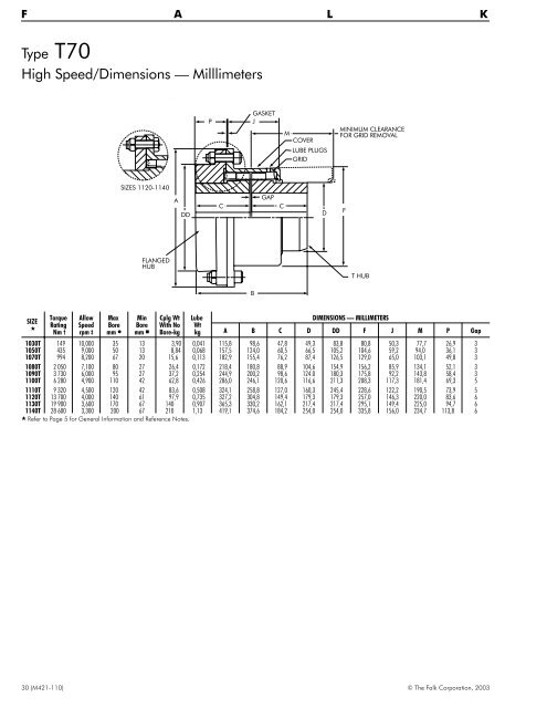
F A L K Type T70 High Speed/Dimensions — Milllimeters P GASKET J M COVER LUBE PLUGS GRID MINIMUM CLEARANCE FOR GRID REMOVAL SIZES 1120-1140 A DD C GAP C D F FLANGED HUB T HUB B SIZE Torque Rating Nm † Allow Speed rpm ‡ Max Bore mm Min Bore mm Cplg Wt With No Bore-kg Lube Wt kg DIMENSIONS — MILLIMETERS A B C D DD F J M P Gap 1030T 149 10,000 35 13 3,90 0,041 115,8 98,6 47,8 49,3 83,8 80,8 50,3 77,7 26,9 3 1050T 435 9,000 50 13 8,84 0,068 157,5 124,0 60,5 66,5 105,2 104,6 59,2 94,0 36,1 3 1070T 994 8,200 67 20 15,6 0,113 182,9 155,4 76,2 87,4 126,5 129,0 65,0 103,1 49,8 3 1080T 2 050 7,100 80 27 26,4 0,172 218,4 180,8 88,9 104,6 154,9 156,2 85,9 134,1 52,1 3 1090T 3 730 6,000 95 27 37,2 0,254 244,9 200,2 98,6 124.0 180,3 175,8 92,2 143,8 58,4 3 1100T 6 280 4,900 110 42 62,8 0,426 286,0 246,1 120,6 116,6 211,3 208,3 117,3 181,4 69,3 5 1110T 9 320 4,500 120 42 83,6 0,508 324,1 258,8 127,0 160,3 245,4 228,6 122,2 190,5 73,9 5 1120T 13 700 4,000 140 61 97,9 0,735 327,2 304,8 149,4 179,3 179,3 257,0 146,3 220,0 83,6 6 1130T 19 900 3,600 170 67 140 0,907 365,3 330,2 162,1 217,4 217,4 295,1 149,4 225,0 94,7 6 1140T 28 600 3,300 200 67 210 1,13 419,1 374,6 184,2 254,0 254,0 335,8 156,0 234,7 113,8 6 Refer to Page 5 for General Information and Reference Notes. 30 (M421-110) © The Falk Corporation, 2003
Type T90 Engine Flywheel Adapter/Dimensions — Millimeters Used primarily to connect the flywheel of an engine to the driven machinery. Adapter plates are designed to accommodate standard SAE J620 bolt patterns. The T90 design provides for higher torque ratings with resulting smaller sizes and lower costs than elastomer coupling designs. The flexible gridmember provides torsional damping in addition to accepting misalignment. Adapter plates are bolted and doweled to the hub to provide a secure joint. Selection — Determine the proper Steelflex coupling size using the selection method. Check size selected against those shown in table below for the clutch size used on the engine flywheel. If the coupling size is not shown, refer all details to Falk. G - (NO. & SIZE OF HOLES) ADAPTER BOLTED AND DOWELED TO HUB BY FALK T AF U BC ADAPTER L B J GAP C COVER GRID D T-HUB LUBE PLUGS A Adapter—Inches CPLG Assembly Allow Cplg Wt DIMENSIONS — MILLIMETERS Max Bore Min AF SIZE Torque Speed No Bore in mm Clutch Bore WR Rating † rpm ‡ T Hub +.000 BC G T mm A B C D J L U Gap Dia – .005 Nm kg 6.5 8.500 7.875 6-.344 .375 .375 1050T 1060T 395 621 3600 3600 50 56 13 20 8,16 10,4 0,025 0,031 138,2 150,9 141,7 150,9 60,5 63,5 66,5 76,2 79,2 91,9 78,0 84,1 127,0 139,7 3 3 375 1070T 904 3600 67 20 13,2 0,038 162,1 176,3 76,2 87,4 95,2 96,8 149,4 3 7.5 9.500 8.750 8-.344 . 375 . 375 1050T 1060T 395 621 3600 3600 50 56 13 20 9,07 10,9 0,034 0,040 138.2 150,9 141,7 150,9 60,5 63,5 66,5 76,2 79,2 91,9 78,0 84,1 127,0 139,7 3 3 . 375 1070T 904 3600 67 20 13,6 0,047 162,1 176,3 76,2 87,4 95,2 96,8 149,4 3 . 375 1050T 395 3600 50 13 9,53 0,044 138,2 141,7 60,5 66,5 79,2 78,0 127,0 3 8 10.375 9.625 6-.406 . 375 . 375 1060T 1070T 621 904 3600 3600 56 67 20 20 11,8 14,5 0,050 0,057 150,9 162,1 150,9 176,3 63,5 76,2 76,2 87,4 91,9 95,2 84,1 96,8 139,7 149,4 3 3 . 500 1080T 1 860 3600 80 27 21,8 0,097 193,5 205,0 88,9 104,6 115,8 112,8 165,1 3 10 12.375 11.625 8-.406 . 500 1080T 1 860 3600 80 27 24,0 0,145 193,5 205,0 88,9 104,6 115,8 112,8 165,1 3 11.5 13.875 13.125 8-.406 . 500 1090T 3 390 3600 95 27 33,6 0,240 212,9 227,3 98,6 124,0 122,2 125,5 190,5 3 14 18.375 17.250 8-.531 . 650 . 750 1100T 1110T 5 710 8 470 2440 2250 110 120 42 42 60,3 73,5 0,791 0,965 251,0 269,7 276,9 292,1 120,6 127,0 142,0 160,3 155,4 161,5 151,4 160,3 212,9 231,9 5 5 16 20.375 19.250 8-.531 . 650 . 750 1100T 1110T 5 710 8 470 2440 2250 110 120 42 42 65,8 79,4 1,097 1,319 251,0 269,7 276,9 292,1 120,6 127,0 142,0 160,3 155,4 161,5 151,4 160,3 212,9 231,9 5 5 18 22.500 21.375 6-.656 . 750 . 750 1110T 1120T 5 710 12 400 2250 2025 120 140 42 61 86,2 110 1,827 2,096 269,7 307,8 292,1 341,1 127,0 149,4 160,3 179,3 161,5 191,5 160,3 185,4 231,9 254,0 5 6 . 900 1130T 10 100 1800 170 67 150 2,849 345,9 373,1 162,1 217,4 195,1 204,7 292,1 6 21 26.500 27.250 12-.656 .900 1.000 1130T 1140T 10 100 26 000 1800 1650 170 200 67 67 168 217 4,553 5,738 345,9 384,0 373,1 419,9 162,1 184,2 217,4 254,0 195,1 201,2 204,7 229,4 298,5 336,6 6 6 1.000 1150T 36 200 1500 215 108 276 7,572 453,1 420,6 182,9 269,2 271,3 231,4 349,3 6 24 28.875 27.250 12-.812 .900 1.000 1130T 1140T 10 100 26 000 1800 1650 170 200 67 67 180 230 5,987 7,332 345,9 384,0 373,1 419,9 162,1 184,2 217,4 254,0 195,1 201,2 204,7 229,4 298,5 336,6 6 6 1.000 1150T 36 200 1500 215 108 289 9,174 453,1 420,6 182,9 269,2 271,5 231,4 349,3 6 Machined as Required See Page 5 for General Information and Reference Notes. For total coupling weight add [ 0,101 x (AF 2 -U 2 )xT]tovalue shown. 1.000 1160T 50 800 1350 240 121 298 . . . 501,9 453,4 198,1 304,8 278,4 248,9 393,7 6 1.250 1170T 67 800 1225 280 134 409 . . . 566,9 495,3 215,9 355,6 307,3 273,0 438,2 6 © The Falk Corporation, 2003 (M421-110) 31