STEELFLEX® - Rexnord
STEELFLEX® - Rexnord
STEELFLEX® - Rexnord

Create successful ePaper yourself
Turn your PDF publications into a flip-book with our unique Google optimized e-Paper software.
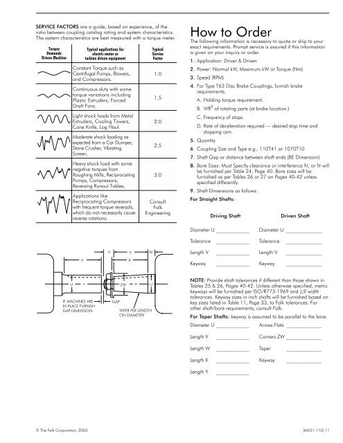
SERVICE FACTORS are a guide, based on experience, of the<br />
ratio between coupling catalog rating and system characteristics.<br />
The system characteristics are best measured with a torque meter.<br />
Torque<br />
Demands<br />
Driven Machine<br />
Typical applications for<br />
electric motor or<br />
turbine driven equipment<br />
Constant Torque such as<br />
Centrifugal Pumps, Blowers,<br />
and Compressors.<br />
Continuous duty with some<br />
torque variations including<br />
Plastic Extruders, Forced<br />
Draft Fans.<br />
Light shock loads from Metal<br />
Extruders, Cooling Towers,<br />
Cane Knife, Log Haul.<br />
Moderate shock loading as<br />
expected from a Car Dumper,<br />
Stone Crusher, Vibrating<br />
Screen.<br />
Heavy shock load with some<br />
negative torques from<br />
Roughing Mills, Reciprocating<br />
Pumps, Compressors,<br />
Reversing Runout Tables,<br />
Applications like<br />
Reciprocating Compressors<br />
with frequent torque reversals,<br />
which do not necessarily cause<br />
reverse rotations.<br />
Typical<br />
Service<br />
Factor<br />
1.0<br />
1.5<br />
2.0<br />
2.5<br />
3.0<br />
Consult<br />
Falk<br />
Engineering<br />
How to Order<br />
The following information is necessary to quote or ship to your<br />
exact requirements. Prompt service is assured if this information<br />
is given on your inquiry or order.<br />
1. Application: Driver & Driven<br />
2. Power: Normal kW, Maximum kW or Torque (Nm)<br />
3. Speed (RPM)<br />
4. For Type T63 Disc Brake Couplings, furnish brake<br />
requirements.<br />
A. Holding torque requirement.<br />
B. WR 2 of rotating parts (at brake location.)<br />
C. Frequency of stops.<br />
D. Rate of deceleration required — desired stop time and<br />
stopping rpm.<br />
5. Quantity<br />
6. Coupling Size and Type e.g., 110T41 or 1070T10<br />
7. Shaft Gap or distance between shaft ends (BE Dimension)<br />
8. Bore Sizes: Must Specify clearance or interference fit, or fit will<br />
be furnished per Table 24, Page 40. Bore sizes will be<br />
furnished as per Tables 26 or 27 on Pages 40-42 unless<br />
specified differently.<br />
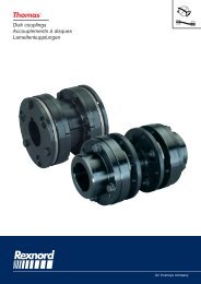
9. Shaft Dimensions as follows:<br />
For Straight Shafts:<br />
Driving Shaft<br />
Driven Shaft<br />
Diameter U _____________<br />
Diameter U ______________<br />
Tolerance _____________ Tolerance ______________<br />
Y<br />
V<br />
W<br />
Length V _____________ Length V ______________<br />
V<br />
X<br />
Keyway _____________ Keyway ______________<br />
U<br />
IF MACHINES ARE<br />
IN PLACE FURNISH<br />
GAP DIMENSION.<br />
GAP<br />
ZW<br />
U<br />
TAPER PER LENGTH<br />
ON DIAMETER<br />
NOTE: Provide shaft tolerances if different than those shown in<br />
Tables 25 & 26, Pages 40-42. Unless otherwise specified, metric<br />
keyways will be furnished per ISO/R773-1969 and J S 9 width<br />
tolerances. Keyway sizes in inch shafts will be furnished based on<br />
key sizes listed in Table 11, Page 33, to Falk tolerances. For<br />
other shaft/bore requirements, consult Falk.<br />
For Taper Shafts: keyway is assumed to be parallel to the bore.<br />
Diameter U _____________ Across Flats ______________<br />
Length V _____________ Corners ZW ______________<br />
Length W _____________ Taper ______________<br />
Length X _____________ Keyway ______________<br />
Length Y<br />
_____________<br />
© The Falk Corporation, 2003 (M421-110) 11