STEELFLEX® - Rexnord
STEELFLEX® - Rexnord
STEELFLEX® - Rexnord

Create successful ePaper yourself
Turn your PDF publications into a flip-book with our unique Google optimized e-Paper software.
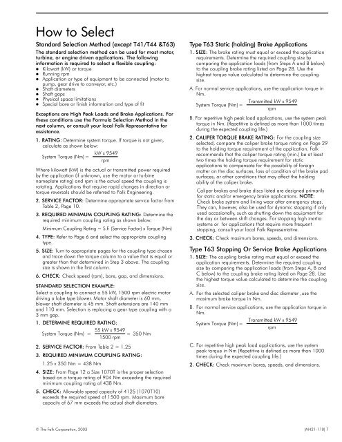
How to Select<br />
Standard Selection Method (except T41/T44 &T63)<br />
The standard selection method can be used for most motor,<br />
turbine, or engine driven applications. The following<br />
information is required to select a flexible coupling:<br />
Kilowatt (kW) or torque<br />
Running rpm<br />
Application or type of equipment to be connected (motor to<br />
pump, gear drive to conveyor, etc.)<br />
Shaft diameters<br />
Shaft gaps<br />
Physical space limitations<br />
Special bore or finish information and type of fit<br />
Exceptions are High Peak Loads and Brake Applications. For<br />
these conditions use the Formula Selection Method in the<br />
next column, or consult your local Falk Representative for<br />
assistance.<br />
1. RATING: Determine system torque. If torque is not given,<br />
calculate as shown below:<br />
kW x 9549<br />
System Torque (Nm) =<br />
rpm<br />
Where kilowatt (kW) is the actual or transmitted power required<br />
by the application (if unknown, use the motor or turbine<br />
nameplate rating) and rpm is the actual speed the coupling is<br />
rotating. Applications that require rapid changes in direction or<br />
torque reversals should be referred to Falk Engineering.<br />
2. SERVICE FACTOR: Determine appropriate service factor from<br />
Table 2, Page 10.<br />
3. REQUIRED MINIMUM COUPLING RATING: Determine the<br />
required minimum coupling rating as shown below:<br />
Minimum Coupling Rating = S.F. (Service Factor) x Torque (Nm)<br />
4. TYPE: Refer to Page 6 and select the appropriate coupling<br />
type.<br />
5. SIZE: Turn to appropriate pages for the coupling type chosen<br />
and trace down the torque column to a value that is equal or<br />
greater than that determined in Step 3 above. The coupling<br />
size is shown in the first column.<br />
6. CHECK: Check speed (rpm), bore, gap, and dimensions.<br />
STANDARD SELECTION EXAMPLE:<br />
Select a coupling to connect a 55 kW, 1500 rpm electric motor<br />
driving a lobe type blower. Motor shaft diameter is 60 mm,<br />
blower shaft diameter is 45 mm. Shaft extensions are 140 mm<br />
and 110 mm. Selection is replacing a gear type coupling with a<br />
3 mm gap.<br />
1. DETERMINE REQUIRED RATING:<br />
55 kW x 9549<br />
System Torque (Nm) = = 350 Nm<br />
1500 rpm<br />
2. SERVICE FACTOR: From Table 2 = 1.25<br />
3. REQUIRED MINIMUM COUPLING RATING:<br />
1.25 x 350 Nm = 438 Nm<br />
4. SIZE: From Page 12 a Size 1070T is the proper selection<br />
based on a torque rating of 904 Nm exceeding the required<br />
minimum coupling rating of 438 Nm.<br />
5. CHECK: Allowable speed capacity of 4125 (1070T10)<br />
exceeds the required speed of 1500 rpm. Maximum bore<br />
capacity of 67 mm exceeds the actual shaft diameters.<br />
Type T63 Static (holding) Brake Applications<br />
1. SIZE: The brake rating must equal or exceed the application<br />
requirements. Determine the required coupling size by<br />
comparing the application loads (from Steps A and B below)<br />
to the coupling brake rating listed on Page 28. Use the<br />
highest torque value calculated to determine the coupling<br />
size.<br />
A. For normal service applications, use the application torque in<br />
Nm.<br />
Transmitted kW x 9549<br />
System Torque (Nm) =<br />
rpm<br />
B. For repetitive high peak load applications, use the system peak<br />
torque in Nm. (Repetitive is defined as more than 1000 times<br />
during the expected coupling life.)<br />
2. CALIPER TORQUE BRAKE RATING: For the coupling size<br />
selected, compare the caliper brake torque rating on Page 29<br />
to the holding torque requirement of the application. Falk<br />
recommends that the caliper torque rating (min.) be at least<br />
two times the holding torque requirement for static<br />
applications to compensate for the possibility of foreign<br />
matter on the disc surfaces, loss of condition of the brake pad<br />
surfaces, or other conditions that may affect the holding<br />
ability of the caliper brake.<br />
Caliper brakes and brake discs listed are designed primarily<br />
for static and/or emergency brake applications. NOTE:<br />
Check brake system and lining wear after emergency stops.<br />
They can, however, also be used for dynamic stopping if only<br />
used occasionally, such as shutting down the equipment for<br />
the day or between shift changes. For stopping high inertia<br />
systems or for applications that require more frequent<br />
stopping, consult your local Falk Representative.<br />
3. CHECK: Check maximum bores, speeds, and dimensions.<br />
Type T63 Stopping Or Service Brake Applications<br />
1. SIZE: The coupling brake rating must equal or exceed the<br />
application requirements. Determine the required coupling<br />
size by comparing the application loads (from Steps A, B and<br />
C below) to the coupling brake rating listed on Page 28. Use<br />
the highest torque value calculated to determine the coupling<br />
size.<br />
A. For the selected caliper brake and disc diameter ,use the<br />
maximum brake torque in Nm.<br />
B. For normal service applications, use the application torque in<br />
Nm.<br />
Transmitted kW x 9549<br />
System Torque (Nm) =<br />
rpm<br />
C. For repetitive high peak load applications, use the system<br />
peak torque in Nm (Repetitive is defined as more than 1000<br />
times during the expected coupling life.)<br />
2. CHECK: Check maximum bores, speeds, and dimensions.<br />
© The Falk Corporation, 2003 (M421-110) 7