STEELFLEX® - Rexnord
STEELFLEX® - Rexnord
STEELFLEX® - Rexnord

You also want an ePaper? Increase the reach of your titles
YUMPU automatically turns print PDFs into web optimized ePapers that Google loves.
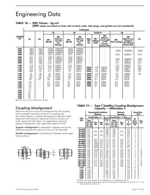
Engineering Data<br />
TABLE 18 — WR2 Values – kg-m2<br />
(WR2 values are based on hubs with no bore; seals, lube plugs, and gaskets are not considered)<br />
COUPLING<br />
SIZE<br />
T10<br />
T20<br />
WR 2<br />
(Min BE)<br />
Coupling Type<br />
T31 T35 T10/G82 T50<br />
WR2<br />
Added Per<br />
mm of BE<br />
Over<br />
Minimum<br />
WR 2<br />
(Min BE)<br />
WR2<br />
Added Per<br />
mm of BE<br />
Over<br />
Minimum<br />
Rigid<br />
Hub<br />
Size<br />
WR 2<br />
(Without<br />
Shaft)<br />
WR2<br />
Added Per<br />
mm of Length<br />
of “SD”<br />
Diameter<br />
Between Hubs<br />
WR 2<br />
(Each Coupling)<br />
WR2<br />
Added Per mm<br />
of length of<br />
“SD” Diameter<br />
Between Hubs<br />
1020T 0,0014 0,0016 0,00286 0,00000207 0,00214 0,00000207 . . . . . . . . . . . . . . . . . .<br />
1030T 0,0022 0,0023 0,00449 0,00000484 0,00336 0,00000484 . . . . . . . . . 0,00434 0,000000500 0,00434<br />
1040T 0,0033 0,0035 0,00930 0,00000876 0,00629 0,00000876 . . . . . . . . . . . . . . . . . .<br />
1050T 0,0073 0,0075 0,0181 0,0000161 0,0127 0,0000161 . . . . . . . . . 0,0181 0,00000161 0,0181<br />
1060T 0,012 0,012 0,0387 0,0000274 0,0253 0,0000274 . . . . . . . . . . . . . . . . . .<br />
1070T 0,019 0,018 0,0513 0,0000468 0,0349 0,0000468 . . . . . . . . . 0,0422 0,00000509 0,0420<br />
1080T 0,045 0,043 0,116 0,0000964 0,0804 0,0000964 . . . . . . . . . 0,101 0,0000124 0,101<br />
1090T 0,079 0,080 0,236 0,000187 0,157 0,000187 . . . . . . . . . 0,177 0,0000258 0,176<br />
1100T 0,178 0,178 0,514 0,000313 0,346 0,000313 . . . . . . . . . 0,417 0,0000629 0,417<br />
1110T 0,270 0,272 0,798 0,000523 0,534 0,000523 1035G 0,787 0,000130 0,699 0,0000916 0,697<br />
1120T 0,514 0,472 1,56 0,000817 1,04 0,000817 1040G 1,51 0,000199 0,801 0,000162 0,800<br />
1130T 0,990 1,05 2,51 0,00176 1,75 0,00176 1045G 2,56 0,000412 1,42 0,000266 1,42<br />
1140T 1,85 1,88 4,35 0,00326 3,10 0,00326 1050G 4,78 0,000879 2,81 0,000348 2,80<br />
1150T 3,49 3,29 9,00 0,00276 6,24 0,00276 1055G 8,23 0,00130 3,04 0,000559<br />
1160T 5,82 6,03 12,8 0,00454 9,90 0,00454 1060G 12,1 0,00209 9,13 0,00130<br />
1170T 10,4 10,4 24,8 0,00909 17,6 0,00909 1070G 23,7 0,00318 15,0 0,00130<br />
1180T 18,3 . . . 39,7 0,0138 29,0 0,0138 1080G 38,3 0,00466 25,8 0,00209<br />
1190T 26,2 . . . 65,0 0,0214 45,6 0,0214 1090G 62,2 0,00659 36,9 0,00318<br />
1200T 43,6 . . . 93,5 0,0381 68,5 0,0381 1100G 92,7 0,00908 59,8 0,00466<br />
1210T 75,6<br />
1220T 113<br />
1230T 175<br />
1240T 339<br />
1250T 525<br />
1260T 712<br />
Values shown are for standard hub lengths.<br />
T70<br />
Coupling Misalignment<br />
Maximum life and minimum maintenance for the coupling<br />
and connected machinery will result if couplings are<br />
accurately aligned. Coupling life expectancy between initial<br />
alignment and maximum operating limits is a function of<br />
load, speed and lubrication. For applications requiring<br />
greater misalignment, refer application details to Falk.<br />
Angular misalignment is expressed in degrees and as the<br />
difference between the value of X minus Y, as illustrated.<br />
Parallel misalignment is the distance P between shaft center<br />
lines as shown.<br />
Y<br />
X<br />
P<br />
GAP<br />
TABLE 19 —<br />
CPLG<br />
SIZE<br />
Type T Steelflex Coupling Misalignment<br />
Capacity — Millimeters <br />
Recommended Installation<br />
Maximum<br />
Parallel Offset – P<br />
Types<br />
T10, T20<br />
T31, T35<br />
T41, T63<br />
Type<br />
T50<br />
Type<br />
T70<br />
Maximum<br />
Operating<br />
Angular Parallel Offset – P Angular<br />
(1/16 °) Types<br />
(1/4 °)<br />
X T10, T20 Type X<br />
minus T31, T35 T70 minus<br />
Y T41, T63<br />
Y<br />
Normal Gap<br />
±10%<br />
All<br />
Types<br />
Except<br />
T31<br />
Type<br />
T31<br />
20/1020T 0,15 . . . . . . 0,08 0,30 . . . 0,25 3 5<br />
30/1030T 0,15 0,05 0,08 0,08 0,30 0,15 0,30 3 5<br />
40/1040T 0,15 . . . . . . 0,08 0,30 . . . 0,33 3 5<br />
50/1050T 0,20 0,05 0,10 0,10 0,41 0,20 0,41 3 5<br />
60/1060T 0,20 . . . . . . 0,13 0,41 . . . 0,46 3 5<br />
70/1070T 0,20 0,05 0,10 0,13 0,41 0,20 0,51 3 5<br />
80/1080T 0,20 0,05 0,10 0,15 0,41 0,20 0,61 3 5<br />
90/1090T 0,20 0,078 0,10 0,18 0,41 0,20 0,71 3 5<br />
100/1100T 0,25 0,078 0,13 0,20 0,51 0,25 0,84 5 6<br />
110/1110T 0,25 0,078 0,13 0,23 0,51 0,25 0,91 5 6<br />
120/1120T 0,28 0,078 0,15 0,25 0,56 0,28 1,02 6 10<br />
130/1130T 0,28 0,10 0,15 0,30 0,56 0,28 1,19 6 10<br />
140/1140T 0,28 0,10 0,15 0,33 0,56 0,28 1,35 6 10<br />
150/1150T 0,30 0,10 0,15 0,41 0,61 0,30 1,57 6 10<br />
160/1160T 0,30 0,13 0,15 0,46 0,61 0,30 1,78 6 10<br />
170/1170T 0,30 0,13 0,15 0,51 0,61 0,30 2,01 6 10<br />
180/1180T 0,38 0,13 0,20 0,56 0,76 0,38 2,26 6 10<br />
190/1190T 0,38 0,15 0,20 0,61 0,76 0,38 2,46 6 10<br />
200/1200T 0,38 0,15 0,20 0,69 0,76 0,38 2,72 6 10<br />
1210T 0,456 . . . . . . 0,74 0,91 . . . 3,00 13 . . .<br />
1220T 0,456 . . . . . . 0,81 0,91 . . . 3,28 13 . . .<br />
1230T 0,456 . . . . . . 0,89 0,97 . . . 3,61 13 . . .<br />
1240T 0,48 . . . . . . 0,97 0,97 . . . 3,91 13 . . .<br />
1250T 0,501 . . . . . . 1,07 1,02 . . . 4,29 13 . . .<br />
1260T 0,501 . . . . . . 1,17 1,02 . . . 4,65 13 . . .<br />
Values may be combined for an installation or an operating condition.<br />
Operating offset limits between Type T50 Floating Shaft Assembly is a function of 1 / 4 ° and<br />
distance between shaft ends.<br />
© The Falk Corporation, 2003 (M421-110) 37