STEELFLEX® - Rexnord
STEELFLEX® - Rexnord
STEELFLEX® - Rexnord

Create successful ePaper yourself
Turn your PDF publications into a flip-book with our unique Google optimized e-Paper software.
F A L K<br />
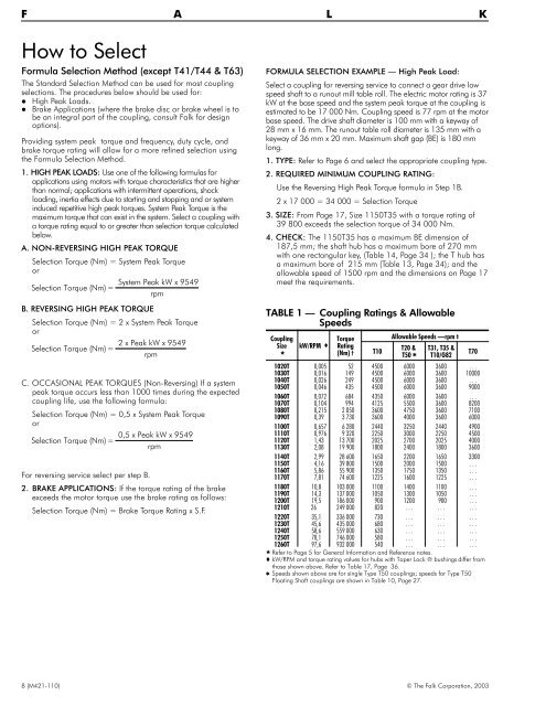
How to Select<br />
Formula Selection Method (except T41/T44 & T63)<br />
The Standard Selection Method can be used for most coupling<br />
selections. The procedures below should be used for:<br />
High Peak Loads.<br />
Brake Applications (where the brake disc or brake wheel is to<br />
be an integral part of the coupling, consult Falk for design<br />
options).<br />
Providing system peak torque and frequency, duty cycle, and<br />
brake torque rating will allow for a more refined selection using<br />
the Formula Selection Method.<br />
1. HIGH PEAK LOADS: Use one of the following formulas for<br />
applications using motors with torque characteristics that are higher<br />
than normal; applications with intermittent operations, shock<br />
loading, inertia effects due to starting and stopping and or system<br />
induced repetitive high peak torques. System Peak Torque is the<br />
maximum torque that can exist in the system. Select a coupling with<br />
a torque rating equal to or greater than selection torque calculated<br />
below.<br />
A. NON-REVERSING HIGH PEAK TORQUE<br />
Selection Torque (Nm) = System Peak Torque<br />
or<br />
System Peak kW x 9549<br />
Selection Torque (Nm) =<br />
rpm<br />
B. REVERSING HIGH PEAK TORQUE<br />
Selection Torque (Nm) =2xSystem Peak Torque<br />
or<br />
2 x Peak kW x 9549<br />
Selection Torque (Nm) =<br />
rpm<br />
C. OCCASIONAL PEAK TORQUES (Non-Reversing) If a system<br />
peak torque occurs less than 1000 times during the expected<br />
coupling life, use the following formula:<br />
Selection Torque (Nm) = 0,5 x System Peak Torque<br />
or<br />
0,5 x Peak kW x 9549<br />
Selection Torque (Nm) =<br />
rpm<br />
For reversing service select per step B.<br />
2. BRAKE APPLICATIONS: If the torque rating of the brake<br />
exceeds the motor torque use the brake rating as follows:<br />
Selection Torque (Nm) = Brake Torque Rating x S.F.<br />
FORMULA SELECTION EXAMPLE — High Peak Load:<br />
Select a coupling for reversing service to connect a gear drive low<br />
speed shaft to a runout mill table roll. The electric motor rating is 37<br />
kW at the base speed and the system peak torque at the coupling is<br />
estimated to be 17 000 Nm. Coupling speed is 77 rpm at the motor<br />
base speed. The drive shaft diameter is 100 mm with a keyway of<br />
28 mm x 16 mm. The runout table roll diameter is 135 mm with a<br />
keyway of 36 mm x 20 mm. Maximum shaft gap (BE) is 180 mm<br />
long.<br />
1. TYPE: Refer to Page 6 and select the appropriate coupling type.<br />
2. REQUIRED MINIMUM COUPLING RATING:<br />
Use the Reversing High Peak Torque formula in Step 1B.<br />
2 x 17 000 = 34 000 = Selection Torque<br />
3. SIZE: From Page 17, Size 1150T35 with a torque rating of<br />
39 800 exceeds the selection torque of 34 000 Nm.<br />
4. CHECK: The 1150T35 has a maximum BE dimension of<br />
187,5 mm; the shaft hub has a maximum bore of 270 mm<br />
with one rectangular key, (Table 14, Page 34 ); the T hub has<br />
a maximum bore of 215 mm (Table 13, Page 34); and the<br />
allowable speed of 1500 rpm and the dimensions on Page 17<br />
meet the requirements.<br />
TABLE 1 — Coupling Ratings & Allowable<br />
Speeds<br />
Coupling<br />
Size<br />
<br />
kW/RPM <br />
Torque<br />
Rating<br />
(Nm) †<br />
T10<br />
Allowable Speeds —rpm ‡<br />
T20 &<br />
T50 <br />
T31, T35 &<br />
T10/G82<br />
1020T 0,005 52 4500 6000 3600 . . .<br />
1030T 0,016 149 4500 6000 3600 10000<br />
1040T 0,026 249 4500 6000 3600 . . .<br />
1050T 0,046 435 4500 6000 3600 9000<br />
1060T 0,072 684 4350 6000 3600 . . .<br />
1070T 0,104 994 4125 5500 3600 8200<br />
1080T 0,215 2 050 3600 4750 3600 7100<br />
1090T 0,39 3 730 3600 4000 3600 6000<br />
1100T 0,657 6 280 2440 3250 2440 4900<br />
1110T 0,976 9 320 2250 3000 2250 4500<br />
1120T 1,43 13 700 2025 2700 2025 4000<br />
1130T 2,08 19 900 1800 2400 1800 3600<br />
1140T 2,99 28 600 1650 2200 1650 3300<br />
1150T 4,16 39 800 1500 2000 1500 . . .<br />
1160T 5,86 55 900 1350 1750 1350 . . .<br />
1170T 7,81 74 600 1225 1600 1225 . . .<br />
1180T 10,8 103 000 1100 1400 1100 . . .<br />
1190T 14,3 137 000 1050 1300 1050 . . .<br />
1200T 19,5 186 000 900 1200 900 . . .<br />
1210T 26 249 000 820 . . . . . . . . .<br />
1220T 35,1 336 000 730 . . . . . . . . .<br />
1230T 45,6 435 000 680 . . . . . . . . .<br />
1240T 58,6 559 000 630 . . . . . . . . .<br />
1250T 78,1 746 000 580 . . . . . . . . .<br />
1260T 97,6 932 000 540 . . . . . . . . .<br />
Refer to Page 5 for General Information and Reference notes.<br />
kW/RPM and torque rating values for hubs with Taper Lock ® bushings differ from<br />
those shown above. Refer to Table 17, Page 36.<br />
Speeds shown above are for single Type T50 couplings; speeds for Type T50<br />
Floating Shaft couplings are shown in Table 10, Page 27.<br />
T70<br />
8 (M421-110) © The Falk Corporation, 2003