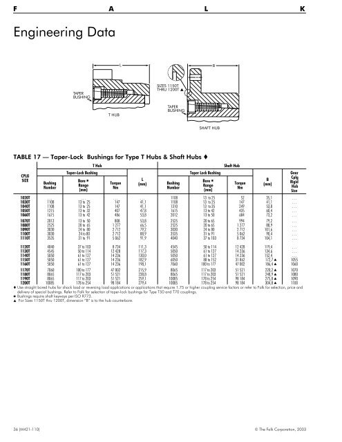
F A L K Engineering Data L B TAPER BUSHING SIZES 1150T THRU 1200T THUB TAPER BUSHING SHAFT HUB TABLE 17 — Taper-Lock CPLG SIZE Bushing Number T Hub Taper-Lock Bushing Bore Range (mm) Bushings for Type T Hubs & Shaft Hubs Torque Nm L (mm) Bushing Number Taper Lock Bushing Bore Range (mm) Shaft Hub 1020T . . . . . . . . . . . . 1108 13 to 25 52 35,1 . . . 1030T 1108 13 to 25 147 41,1 1108 13 to 25 147 41,1 . . . 1040T 1108 13 to 25 147 41,1 1310 13 to 35 249 53,8 . . . 1050T 1215 13 to 32 407 47,8 1615 13 to 42 435 60,4 . . . 1060T 1615 13 to 42 486 53,8 2012 13 to 50 684 73,2 . . . 1070T 2012 13 to 50 808 53,8 2525 20 to 65 994 79,2 . . . 1080T 2525 20 to 65 1 277 66,5 2525 20 to 65 1 277 88,9 . . . 1090T 3030 24 to 80 2 712 79,2 3030 24 to 80 2 712 101,6 . . . 1100T 3030 24 to 80 2 712 88,9 3535 31 to 91 5 062 90,4 . . . 1110T 3535 31 to 91 5 062 91,9 4040 37 to 103 8 734 104,1 . . . 1120T 4040 37 to 103 8 734 111,3 4545 50 to 114 12 428 119,4 . . . 1130T 4545 50 to 114 12 428 117,3 5050 61 to 127 14 236 134,6 . . . 1140T 5050 61 to 127 14 236 130,0 5050 61 to 127 14 236 152,4 . . . 1150T 5050 61 to 127 14 236 182,9 6050 88 to 152 31 862 172,7 1055 1160T 5050 61 to 127 14 236 198,1 7060 100 to 177 47 002 186,4 1060 1170T 7060 100 to 177 47 002 215,9 8065 117 to 203 51 521 220,2 1070 1180T 8065 117 to 203 51 521 238,8 8065 117 to 203 51 521 248,9 1080 1190T 8065 117 to 203 51 521 259,1 10085 178 to 254 98 184 275,8 1090 1200T 10085 178 to 254 98 184 279,4 10085 178 to 254 98 184 304,8 1100 Use straight bored hubs for shock load or reversing load applications or applications that require 1.75 or higher coupling service factors or refer to Falk for selection, price and delivery of special bushings. Refer to Falk for selection of taper-lock bushings for Type T50 and T70 couplings. Bushings require shaft keyways per ISO R773. For Sizes 1150T thru 1200T, dimension “B” is to the hub counterbore. Torque Nm B (mm) Gear Cplg Rigid Hub Size 36 (M421-110) © The Falk Corporation, 2003
Engineering Data TABLE 18 — WR2 Values – kg-m2 (WR2 values are based on hubs with no bore; seals, lube plugs, and gaskets are not considered) COUPLING SIZE T10 T20 WR 2 (Min BE) Coupling Type T31 T35 T10/G82 T50 WR2 Added Per mm of BE Over Minimum WR 2 (Min BE) WR2 Added Per mm of BE Over Minimum Rigid Hub Size WR 2 (Without Shaft) WR2 Added Per mm of Length of “SD” Diameter Between Hubs WR 2 (Each Coupling) WR2 Added Per mm of length of “SD” Diameter Between Hubs 1020T 0,0014 0,0016 0,00286 0,00000207 0,00214 0,00000207 . . . . . . . . . . . . . . . . . . 1030T 0,0022 0,0023 0,00449 0,00000484 0,00336 0,00000484 . . . . . . . . . 0,00434 0,000000500 0,00434 1040T 0,0033 0,0035 0,00930 0,00000876 0,00629 0,00000876 . . . . . . . . . . . . . . . . . . 1050T 0,0073 0,0075 0,0181 0,0000161 0,0127 0,0000161 . . . . . . . . . 0,0181 0,00000161 0,0181 1060T 0,012 0,012 0,0387 0,0000274 0,0253 0,0000274 . . . . . . . . . . . . . . . . . . 1070T 0,019 0,018 0,0513 0,0000468 0,0349 0,0000468 . . . . . . . . . 0,0422 0,00000509 0,0420 1080T 0,045 0,043 0,116 0,0000964 0,0804 0,0000964 . . . . . . . . . 0,101 0,0000124 0,101 1090T 0,079 0,080 0,236 0,000187 0,157 0,000187 . . . . . . . . . 0,177 0,0000258 0,176 1100T 0,178 0,178 0,514 0,000313 0,346 0,000313 . . . . . . . . . 0,417 0,0000629 0,417 1110T 0,270 0,272 0,798 0,000523 0,534 0,000523 1035G 0,787 0,000130 0,699 0,0000916 0,697 1120T 0,514 0,472 1,56 0,000817 1,04 0,000817 1040G 1,51 0,000199 0,801 0,000162 0,800 1130T 0,990 1,05 2,51 0,00176 1,75 0,00176 1045G 2,56 0,000412 1,42 0,000266 1,42 1140T 1,85 1,88 4,35 0,00326 3,10 0,00326 1050G 4,78 0,000879 2,81 0,000348 2,80 1150T 3,49 3,29 9,00 0,00276 6,24 0,00276 1055G 8,23 0,00130 3,04 0,000559 1160T 5,82 6,03 12,8 0,00454 9,90 0,00454 1060G 12,1 0,00209 9,13 0,00130 1170T 10,4 10,4 24,8 0,00909 17,6 0,00909 1070G 23,7 0,00318 15,0 0,00130 1180T 18,3 . . . 39,7 0,0138 29,0 0,0138 1080G 38,3 0,00466 25,8 0,00209 1190T 26,2 . . . 65,0 0,0214 45,6 0,0214 1090G 62,2 0,00659 36,9 0,00318 1200T 43,6 . . . 93,5 0,0381 68,5 0,0381 1100G 92,7 0,00908 59,8 0,00466 1210T 75,6 1220T 113 1230T 175 1240T 339 1250T 525 1260T 712 Values shown are for standard hub lengths. T70 Coupling Misalignment Maximum life and minimum maintenance for the coupling and connected machinery will result if couplings are accurately aligned. Coupling life expectancy between initial alignment and maximum operating limits is a function of load, speed and lubrication. For applications requiring greater misalignment, refer application details to Falk. Angular misalignment is expressed in degrees and as the difference between the value of X minus Y, as illustrated. Parallel misalignment is the distance P between shaft center lines as shown. Y X P GAP TABLE 19 — CPLG SIZE Type T Steelflex Coupling Misalignment Capacity — Millimeters Recommended Installation Maximum Parallel Offset – P Types T10, T20 T31, T35 T41, T63 Type T50 Type T70 Maximum Operating Angular Parallel Offset – P Angular (1/16 °) Types (1/4 °) X T10, T20 Type X minus T31, T35 T70 minus Y T41, T63 Y Normal Gap ±10% All Types Except T31 Type T31 20/1020T 0,15 . . . . . . 0,08 0,30 . . . 0,25 3 5 30/1030T 0,15 0,05 0,08 0,08 0,30 0,15 0,30 3 5 40/1040T 0,15 . . . . . . 0,08 0,30 . . . 0,33 3 5 50/1050T 0,20 0,05 0,10 0,10 0,41 0,20 0,41 3 5 60/1060T 0,20 . . . . . . 0,13 0,41 . . . 0,46 3 5 70/1070T 0,20 0,05 0,10 0,13 0,41 0,20 0,51 3 5 80/1080T 0,20 0,05 0,10 0,15 0,41 0,20 0,61 3 5 90/1090T 0,20 0,078 0,10 0,18 0,41 0,20 0,71 3 5 100/1100T 0,25 0,078 0,13 0,20 0,51 0,25 0,84 5 6 110/1110T 0,25 0,078 0,13 0,23 0,51 0,25 0,91 5 6 120/1120T 0,28 0,078 0,15 0,25 0,56 0,28 1,02 6 10 130/1130T 0,28 0,10 0,15 0,30 0,56 0,28 1,19 6 10 140/1140T 0,28 0,10 0,15 0,33 0,56 0,28 1,35 6 10 150/1150T 0,30 0,10 0,15 0,41 0,61 0,30 1,57 6 10 160/1160T 0,30 0,13 0,15 0,46 0,61 0,30 1,78 6 10 170/1170T 0,30 0,13 0,15 0,51 0,61 0,30 2,01 6 10 180/1180T 0,38 0,13 0,20 0,56 0,76 0,38 2,26 6 10 190/1190T 0,38 0,15 0,20 0,61 0,76 0,38 2,46 6 10 200/1200T 0,38 0,15 0,20 0,69 0,76 0,38 2,72 6 10 1210T 0,456 . . . . . . 0,74 0,91 . . . 3,00 13 . . . 1220T 0,456 . . . . . . 0,81 0,91 . . . 3,28 13 . . . 1230T 0,456 . . . . . . 0,89 0,97 . . . 3,61 13 . . . 1240T 0,48 . . . . . . 0,97 0,97 . . . 3,91 13 . . . 1250T 0,501 . . . . . . 1,07 1,02 . . . 4,29 13 . . . 1260T 0,501 . . . . . . 1,17 1,02 . . . 4,65 13 . . . Values may be combined for an installation or an operating condition. Operating offset limits between Type T50 Floating Shaft Assembly is a function of 1 / 4 ° and distance between shaft ends. © The Falk Corporation, 2003 (M421-110) 37