Quick Setup Guide M300 FLOW Transmitter - METTLER TOLEDO
Quick Setup Guide M300 FLOW Transmitter - METTLER TOLEDO
Quick Setup Guide M300 FLOW Transmitter - METTLER TOLEDO
You also want an ePaper? Increase the reach of your titles
YUMPU automatically turns print PDFs into web optimized ePapers that Google loves.
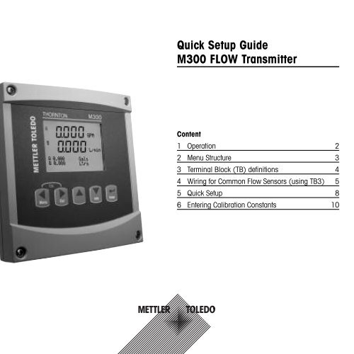
<strong>Quick</strong> <strong>Setup</strong> <strong>Guide</strong><br />
<strong>M300</strong> <strong>FLOW</strong> <strong>Transmitter</strong><br />
Content<br />
1 Operation 2<br />
2 Menu Structure 3<br />
3 Terminal Block (TB) definitions 4<br />
4 Wiring for Common Flow Sensors (using TB3) 5<br />
5 <strong>Quick</strong> <strong>Setup</strong> 8<br />
6 Entering Calibration Constants 10
1 Operation<br />
Entry of data values, selection of data entry options<br />
Use the key to increase or the key to decrease a digit. Use the same keys to navigate<br />
within a selection of values or options of a data entry field.<br />
Note: Some screens require configuring multiple values via the same data field (ex: configuring<br />
multiple setpoints). Be sure to use the or key to return to the primary field and the<br />
or key to toggle between all configuration options before entering to the next display screen.<br />
<br />
Navigation with in Display<br />
If a is displayed on the bottom right hand corner of the display, you can use the<br />
or the key to navigate to it. If you click [ENTER] you will navigate backwards through<br />
the menu (go back one screen). This can be a very useful option to move back up the menu tree<br />
without having to exit into the measuring mode and re-enter the menu.<br />
Exit menu<br />
Note: Exit the menu at any time by pressing the and key simultaneously (escape).<br />
The transmitter returns to the Measurement mode.<br />
”Save changes” dialog<br />
Three options are possible for the ”Save changes” dialog:<br />
– ”Yes & Exit”: Save changes and exit to measuring mode<br />
– ”Yes & ”: Save changes and go back one screen<br />
– ”No & Exit”: Don’t save changes and exit to measuring mode<br />
The ”Yes & ” option is very useful if you want to continue configuring without having to<br />
re-enter the menu.<br />
2
2 Menu Structure<br />
Measurement<br />
Mode <strong>M300</strong><br />
Menu<br />
Cal<br />
Info<br />
Messages<br />
Model/Software<br />
Revision<br />
<strong>Quick</strong> <strong>Setup</strong> Configure System PID <strong>Setup</strong> Service<br />
Measurement<br />
Analog Outputs<br />
Set Points<br />
Alarm<br />
Display<br />
Hold Outputs<br />
Set Language<br />
USB<br />
Passwords<br />
Set/Clear Lockout<br />
Reset<br />
PID <strong>Setup</strong><br />
Tune Parameters<br />
Mode<br />
Diagnostics<br />
Calibrate<br />
Tech Service<br />
3
3 Terminal Block (TB) definitions<br />
Power connections are labeled –Nfor Neutral and +L for Line, for 100 to 240 VAC or 20 – 30 VDC.<br />
1<br />
⁄4 DIN 1<br />
⁄2<br />
TB2 for<br />
DIN<br />
⁄4 DIN<br />
TB4 TB3<br />
1 AO1+<br />
1 9<br />
2 AO1–/AO2–<br />
3 AO2+<br />
9 1<br />
4 –<br />
5 –<br />
9<br />
6 –<br />
TB1A<br />
7 DI1+<br />
1 7<br />
8 DI1–<br />
TB1B 1<br />
9 –<br />
1 7 TB2<br />
TB1A for 1 ⁄4 DIN<br />
1 NO2<br />
2 COM2<br />
3 NC2<br />
4 –<br />
5 –<br />
6 NO4<br />
7 COM4<br />
TB1B for 1 ⁄4 DIN<br />
1 NO1<br />
2 COM1<br />
3 NC1<br />
4 –<br />
5 –<br />
6 NO3<br />
7 COM3<br />
TB2 for 1 ⁄2 DIN<br />
1 AO1+<br />
2 AO1–/AO2–<br />
3 AO2+<br />
4 –<br />
5 –<br />
6 –<br />
7 DI1+<br />
8 DI1–<br />
9 –<br />
1 NO1<br />
2 COM1<br />
3 NC1<br />
4 NO2<br />
5 COM2<br />
6 NC2<br />
7 –<br />
TB1 1 14<br />
1 9 1 9 1 9<br />
TB2 TB3 TB4<br />
TB1 for 1 ⁄2 DIN<br />
8 –<br />
9 –<br />
10 –<br />
11 NO3<br />
12 COM3<br />
13 NO4<br />
14 COM4<br />
NO = normally open (contact is open if unactuated). NC = normally closed (contact is closed if unactuated).<br />
3.1 Sensor Connections – TB3<br />
4<br />
Flow<br />
Pin no.<br />
Function<br />
1 – Not used<br />
2 GND Ground<br />
3 BJ +10 VDC<br />
4 BIN Pulse Input<br />
5 +5V +5 VDC<br />
6 GND Ground<br />
7 AJ +10 VDC<br />
8 AIN Pulse Input<br />
9 +5V +5 VDC<br />
– AJ and AIN refer to connections for channel A.
4 Wiring for Common Flow Sensors (using TB3)<br />
Sensor wiring for most flow sensors is shown below. For other sensors, please see the instruction<br />
manual. Wiring is shown for channel A.<br />
Kit 58 091 032 supplied with the <strong>M300</strong> includes 4 each of the capacitors and resistors shown in the<br />
diagrams below, plus wire nuts for use in completing the wiring.<br />
Data industrial 200 series<br />
Flow sensors<br />
Type: high<br />
black<br />
shield<br />
red<br />
THORNTON 33142-33145,<br />
33159-33162, 33273<br />
1K<br />
0.33uF<br />
TB 3<br />
1<br />
2 GND<br />
3<br />
4<br />
5 +5V<br />
6 GND<br />
7 A J<br />
8 A IN<br />
9 +5V<br />
<strong>M300</strong> transmitter<br />
5
Wiring for Common Flow Sensors (using TB3)<br />
Data industrial 4000 series<br />
Flow sensors<br />
Type: high<br />
black<br />
THORNTON<br />
33174-33177,33171,33172<br />
shield<br />
red<br />
clear<br />
0.33uF<br />
TB 3<br />
1<br />
2 GND<br />
3<br />
4<br />
5 +5V<br />
6 GND<br />
7 A J<br />
8 A IN<br />
9 +5V<br />
<strong>M300</strong> transmitter<br />
Hoffer and Sponsler<br />
Turbine sensors<br />
Type: high<br />
THORNTON<br />
33336-333377 (Hoffer)<br />
33441-33450 (Sponsler)<br />
black<br />
shield<br />
red<br />
white or orange<br />
0.33uF<br />
TB 3<br />
1<br />
2 GND<br />
3<br />
4<br />
5 +5V<br />
6 GND<br />
7 A J<br />
8 A IN<br />
9 +5V<br />
<strong>M300</strong> transmitter<br />
6
shield<br />
red<br />
black<br />
Signet 2507, 2536, 2540<br />
Hall effect<br />
Paddlewheel sensor, Type: high<br />
THORNTON 33282, 33285,<br />
33287, 33298-33305<br />
10K<br />
0.33uF<br />
TB 3<br />
1<br />
2 GND<br />
3<br />
4<br />
5 +5V<br />
6 GND<br />
7 A J<br />
8 A IN<br />
9 +5V<br />
<strong>M300</strong> transmitter<br />
Signet 515 sensor<br />
Type: low<br />
black<br />
shield<br />
red<br />
THORNTON 33189, 33193,<br />
33195, 33186, 33229<br />
TB 3<br />
1<br />
2 GND<br />
3<br />
4<br />
5 +5V<br />
6 GND<br />
7 A J<br />
8 A IN<br />
9 +5V<br />
<strong>M300</strong> transmitter<br />
7
5 <strong>Quick</strong> <strong>Setup</strong> (PATH: Menu/<strong>Quick</strong> <strong>Setup</strong>)<br />
<strong>Quick</strong> <strong>Setup</strong> allows limited configuration of the most common functions of the <strong>M300</strong> Flow transmitter.<br />
Detailed information for each function can be found in the individual sections of the manual.<br />
Enter <strong>Quick</strong> <strong>Setup</strong> mode<br />
While in Measurement mode press<br />
<strong>Setup</strong> and press the [ENTER] key.<br />
75.5 GPM<br />
283.9 L/min<br />
MENU<br />
<strong>Quick</strong> <strong>Setup</strong><br />
to bring up the Menu selection. Select <strong>Quick</strong><br />
Note: To exit <strong>Quick</strong> <strong>Setup</strong> mode at any time press the and keys simultaneously<br />
(Escape). The transmitter returns to the Measurement mode and the old values<br />
remain active.<br />
Flow Sensor Type Selection<br />
Refer to Section 4 for Flow sensor type information.<br />
75.5 GPM<br />
283.9 L/min<br />
SensorType Input High<br />
Measurement Selection<br />
<br />
75.5 GPM<br />
283.9 L/min<br />
a GPM<br />
Analog Output? Yes <br />
Select the desired flow sensor type which corresponds to the type of flow sensor wired<br />
to the transmitter. The choices are High, Low and Type 2.<br />
Select the desired line (a or c) to configure the values to be displayed and whether this<br />
value will have an Analog Output.<br />
Convention:<br />
1st line on display = > a<br />
3rd line on display = > c<br />
75.5 GPM<br />
0.000 Gals<br />
Example:<br />
– By selecting a and GPM as units, the flow rate value will be displayed on the 1st line.<br />
– By selecting c and Gals as units, the total flow value will be displayed on the 3rd line<br />
of the display which has more digits of resolution.<br />
– Selecting None means the display will be blank for the line selected.<br />
8
Analog Outputs<br />
75.5 GPM<br />
Aout1 min= 0.000 GPM<br />
Aout1 max= 0.000 GPM<br />
<br />
By selecting Analog Output Yes on the previous screen the linear 4–20 mA analog output<br />
Aout1 will be setup for measurement a or Aout2 for measurement c when [ENTER]<br />
is pressed. Selecting No means that no analog output is setup.<br />
Aout min and Aout max are the minimum and maximum measurement values for the<br />
4 and 20 mA signal limits respectively.<br />
Set points<br />
75.5 GPM<br />
a Set Point Yes<br />
SP1 Type= High<br />
<br />
After configuring the Analog Output, a Set Point can be configured for that measurement.<br />
If No is selected and [ENTER] is pressed then the <strong>Quick</strong> <strong>Setup</strong> is done and<br />
the menus are exited without setting any set point.<br />
75.5 GPM<br />
SP1 High = 0.000<br />
75.5 GPM<br />
<br />
Selecting Yes and pressing [ENTER] means a Set Point can be configured.<br />
The following Set Point Types can be selected:<br />
– Off (Set Point is Off)<br />
– High (High value has to be set)<br />
– Low (Low value has to be set)<br />
– Outside (High and Low value have to be set)<br />
– Between (High and Low value have to be set)<br />
After setting the Set point value(s) a Relay (none (blank), 1, 2, 3, 4) can be configured<br />
for that Set Point, including delay and hysteresis.<br />
SP1 use Relay #1<br />
<br />
75.5 GPM<br />
Save Change Yes<br />
Press Enter to Exit<br />
<br />
If Yes and [ENTER] is pressed, the display, analog output, set point and relay setups<br />
are stored and the previous values including use of the relay are cancelled.<br />
If No and [ENTER] is pressed then no changes are made and the transmitter will<br />
return to the normal operating mode.<br />
9
6 Entering Calibration Constants (PATH: Cal/Sensor/Edit)<br />
K-factors are supplied with flow sensor documentation, and need to be identified for the specific sensor<br />
pipe size, converted to appropriate units if necessary, and entered for each channel. If a certificate of<br />
calibration with multipoint linearization is provided (some vortex and turbine sensors) refer to the<br />
instruction manual. Multiplier units entered into the <strong>M300</strong> must be pulses per gallon, even if the readout<br />
will be in other units. Enter Adder constants (if provided) in units of GPM.<br />
If K factors are provided in units of GPM/Hz, divide 60 by the K value and enter the result as the<br />
Multiplier, ”M”. For example, a K value of 2 GPM/Hz would result in a Multiplier of 60/2 = 30.<br />
If an offset is provided in Hz, multiply it by the original K factor (in GPM/Hz) and enter the result as the<br />
Adder, ”A”. If an offset is not provided, leave the Adder set to zero.<br />
75.00 GPM<br />
While in Measurement mode press the key. Press the or key to select<br />
”Sensor”. For 4 channel models, select the channel.<br />
Calibrate Sensor<br />
Channel A GPM<br />
<br />
75.00 GPM<br />
Select ”Edit”.<br />
Calibrate Sensor<br />
Channel A Edit<br />
<br />
75.00 GPM<br />
Press Enter to display all calibration constants for the sensor. Change the K-factor ”M”<br />
and Adder ”A”. If no adder is provided, leave this as 0.<br />
M= 1.0000 A=0.0000 <br />
10
75.00 GPM<br />
For multipoint data, please refer to the instruction manual.<br />
K1=100.000 F1=0.0000<br />
K2=100.000 F2=0.0000<br />
75.00 GPM<br />
Select Yes to save the new calibration values and the successful Calibration is confirmed<br />
on the display.<br />
Save Calibration Yes<br />
Press Enter to Exit<br />
<br />
11
A<br />
BR<br />
CH<br />
D<br />
Mettler-Toledo Ges.m.b.H., Südrandstrasse 17, A - 1230 Wien<br />
Phone +43 1 607 43 56, Fax +43 1 604 28 80<br />
Mettler-Toledo Ind. e Com. Ltda., Alameda Araguaia, 451, Alphaville, BR - 06455-000 Barueri / SP<br />
Phone +55 11 4166 7444, Fax +55 11 4166 7401<br />
Mettler-Toledo (Schweiz) GmbH, Im Langacher, Postfach, CH - 8606 Greifensee<br />
Phone +41 44 944 45 45, Fax +41 44 944 45 10<br />
Mettler-Toledo GmbH, Prozeßanalytik, Ockerweg 3, D - 35396 Gießen<br />
Phone +49 641 507 333, Fax +49 641 507 397<br />
F Mettler-Toledo, Analyse Industrielle S.A.S., 30, Boulevard Douaumont, BP 949, F - 75829 Paris Cedex 17<br />
Phone +33 1 47 37 06 00, Fax +33 1 47 37 46 26<br />
J<br />
CN<br />
UK<br />
USA<br />
Mettler-Toledo K.K., Process Division, 4F Izumikan Sanbancho Bldg., 3-8 Sanbancho,<br />
Chiyoda-ku, JP - 102-0075 Tokyo<br />
Phone +81 3 5762 07 06, Fax +81 3 5762 09 71<br />
Mettler-Toledo Instruments (Shanghai) Co. Ltd., 589 Gui Ping Road, Cao He Jing, CN - 200233 Shanghai<br />
Phone +86 21 64 85 04 35, Fax +86 21 64 85 33 51<br />
Mettler-Toledo LTD, 64 Boston Road, Beaumont Leys, GB - Leicester LE4 1AW<br />
Phone +44 116 235 7070, Fax +44 116 236 5500<br />
Mettler-Toledo, Process Analytics, Inc., 36 Middlesex Turnpike, Bedford, MA 01730, USA<br />
Phone +1 781 301 8800, Fax +1 781 271 0681<br />
Mettler-Toledo AG<br />
Process Analytics<br />
Industrie Nord, Im Hackacker 15<br />
CH-8902 Urdorf, Switzerland<br />
Phone +41 44 729 62 11, Fax +41 44 729 66 36<br />
www.mt.com/pro<br />
Subject to technical changes.<br />
© Mettler-Toledo AG 04 /2008.<br />
Printed in Switzerland. 52 121 322


