
You also want an ePaper? Increase the reach of your titles
YUMPU automatically turns print PDFs into web optimized ePapers that Google loves.
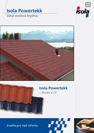
<strong>Isola</strong><br />
<strong>Powertekk</strong><br />
Installation<br />
manual
Introduction<br />
<strong>Isola</strong> <strong>Powertekk</strong> is a steel based, light weight roof<br />
covering system designed to provide an attractive and<br />
economic finish for all types of roofs down to 10° pitch.<br />
The <strong>Isola</strong> <strong>Powertekk</strong> Nordic tile is manufactured from<br />
0.5 mm cold rolled, galvanized steel and weighs only<br />
7.7 kg/m². The steel thickness combined with the Nordic<br />
profile provides superior strength and stability of the<br />
tiles.<br />
<strong>Powertekk</strong> Nordic is available in six colours, coated and<br />
covered with mineral granules,<br />
The <strong>Isola</strong> <strong>Powertekk</strong> CC is manufactured from 0.45 mm<br />
cold rolled, galvanized steel and weighs only 5.0 kg/m².<br />
<strong>Powertekk</strong> CC is available in six colours with a hard<br />
and smooth surface. The <strong>Powertekk</strong> CC coating offers<br />
extremely good colour stability, retention of gloss and<br />
high UV-resistance.<br />
A comprehensive range of accessories is avaliable both<br />
for Nordic and CC, including eaves, ridge, gable end<br />
covers and ventilators, completes the system.<br />
Each tile has a downturned front edge and an upturned<br />
rear edge, and is profiled to provide a strong overlapping<br />
and interlocking roof covering. <strong>Powertekk</strong> tiles are<br />
produced in large format. This enables faster installation<br />
with fewer fixings compared to traditional tile or slate<br />
roofing.<br />
Once installed <strong>Powertekk</strong> tiles provide a durable weathertight<br />
and low maintenance roof.<br />
The Installation Manual contains the basic rules for the<br />
correct installation of <strong>Isola</strong> <strong>Powertekk</strong>. Compliance with<br />
the following directions will guarantee that your roof is<br />
durable and safe.<br />
Please observe the product and installation differences<br />
between the <strong>Powertekk</strong> Nordic and <strong>Powertekk</strong> CC<br />
– especially the differences in the Gable Tiles, and the<br />
difference in batten spacing.<br />
2
Content<br />
General planning details 4<br />
Installation<br />
1. Roof Layout 6<br />
2. Installation, roof surface 7<br />
3. Eaves 10<br />
4. Ridge 11<br />
5. Hip 14<br />
6. Gable with Barge Board Cover 15<br />
7. Gable with Gable Tile 16<br />
8. Valley 18<br />
9. Chimney flashing 20<br />
10. Side wall flashing 21<br />
11. Front wall flashing 22<br />
12. Installation of accessories 23<br />
13. Skylight/roof exit 25<br />
14. Roof windows 26<br />
Calculation of materials<br />
Covered width with Gable Tiles 27<br />
Covered width with Barge Board Cover 28<br />
Covered length of roof eaves to ridge 29<br />
<strong>Powertekk</strong> details of products 30<br />
<strong>Isola</strong> TopSec roof safety accessories<br />
15. Snow guard 32<br />
16. Holders for round timber 34<br />
17. Single steps 35<br />
18. Roof ladder 37<br />
19. Chimney platform 39<br />
20. Safety hooks 41<br />
21. Solar panel support system 42<br />
Technical data 44<br />
3
General planning details<br />
NORDIC CC<br />
Roof pitch<br />
The minimum roof pitch for <strong>Isola</strong> <strong>Powertekk</strong> is 10° (17.6%).<br />
Minimum allowed roof pitch shall be checked against valid<br />
regulations in each country.<br />
Roof underlay<br />
On roof pitches from 10° to 18° the roof should be built with<br />
a wooden or plywood desk covered with a bitumen based<br />
underlayer. All overlaps must be sealed. On roof pitches above<br />
18° there shall as a minimum be installed a breather membrane<br />
designated for use in supported and unsupported pitched roof<br />
applications, including warm, hybrid and cold roofs.<br />
Ventilation<br />
Metal, and therefore metal roofing, does not permit diffusion.<br />
Correct ventilation will prevent condensation problems. In order<br />
to achieve a functionally correct roof with <strong>Isola</strong> <strong>Powertekk</strong> it<br />
is therefore important to ensure satisfactory ventilation of the<br />
space below the tiles. The ventilation shall be arranged to safeguard<br />
a good air circulation from the eaves to the ridge.<br />
Battens and Counterbattens<br />
Counterbattens 30 x 50 mm is recommended. Other dimensions<br />
may be used according to local regulations and good<br />
practice.<br />
Battens 30 x 50 mm is recommended. Standard flashings are<br />
made to fit 30 mm high battens. Where the rafters are widely<br />
spaced, the dimension of the tile battens should be chosen<br />
accordingly to comply with local regulations for load bearing<br />
capacity. Please note that the maximum width of the batten is<br />
65 mm.<br />
Batten distance for <strong>Powertekk</strong> Nordic shall be 369 mm, measured<br />
from front to front of the battens. For <strong>Powertekk</strong> CC the<br />
batten distance shall be 371 mm.<br />
Snow load<br />
<strong>Powertekk</strong> Nordic has been tested for a uniformly distributed<br />
load equal to 21 kN/m² without observing failure or visible permanent<br />
deformations. <strong>Isola</strong> <strong>Powertekk</strong> can be assumed to have<br />
adequate strength and stiffness at all relevant snow loads.<br />
Wind load<br />
The pull through or tear out design capasity is 740 N per fastener,<br />
or 7.4 kN/m² with 4 nails per tile. The capasity is adequate<br />
for all relevant wind loads up to hurricane.<br />
4
Safety in case of fire<br />
<strong>Powertekk</strong> has been tested at roof pitches 15° and 45° according<br />
to the requirements of the DIN 4102, Part 7. Accordingly<br />
<strong>Powertekk</strong> is classified as resistant against radiant heat and<br />
spread of flames at all roof pitches.<br />
<strong>Powertekk</strong> also satisfy the requirements for Class B ROOF (t1)<br />
according to prEN 13501-5 regarding surface spread of flames.<br />
Installation temperature<br />
<strong>Isola</strong> <strong>Powertekk</strong> can be installed at all temperatures likely to be<br />
met in roofing works. However at temperatures below 0° C<br />
extra care is required, particularly when driving nails and cutting<br />
and bending tiles.<br />
Fixing materials<br />
Appropriate nails or screws shall be used to fix <strong>Isola</strong> <strong>Powertekk</strong><br />
to the battens. Nailing can be done manually or with a nailing<br />
gun.<br />
Metal combinations<br />
Due to the risk of galvanic corrosion copper fixings and mounting<br />
parts must not be used in combination with <strong>Powertekk</strong>.<br />
Other metal combinations are not a problem.<br />
Cutting of the tiles<br />
The necessary cutting to size should be done "cold" using suitable<br />
hand shears or guillotine shears. Cutting can also be done<br />
by circular saw with a cutting blade specially for this purpose.<br />
Heat-generating cutting with rotating machines faster than<br />
4000 rpm must not be used. Overheating of the metal when<br />
cutting will damage the corrotion protection (zinc) along the<br />
cut edge.<br />
For <strong>Powertekk</strong> CC sutiable hand shears or guillotine shears are<br />
recommended.<br />
Surface repairs<br />
Surface damages to the roofing should be repaired with the<br />
<strong>Powertekk</strong> Repair Kit. Details made from lead flashing can also<br />
be colour-matched using the Repair Kit. For correct use of the<br />
Repair Kit see instructions included in the set.<br />
Roof safety<br />
For regular services on the roof (chimney sweeper) safe access<br />
should be planned and built in. <strong>Isola</strong> TopSec roof ladders,<br />
chimeny platforms and safety hooks are available and custommade<br />
for <strong>Powertekk</strong>.<br />
5
Roof layout<br />
Spacing of the battens<br />
NORDIC<br />
20 mm 369 mm 369 mm 369 mm 369 mm Y 20 mm<br />
Spacing of the battens<br />
20 mm 371 mm 371 mm 371 mm 371 mm Y 20 mm<br />
CC<br />
The <strong>Isola</strong> <strong>Powertekk</strong> roofing system is installed with a constant<br />
batten spacing of:<br />
369 mm for <strong>Powertekk</strong> Nordic and<br />
371 mm for <strong>Powertekk</strong> CC.<br />
The spacing shall always be measured from the front of a<br />
batten to the front of the next one.<br />
The first batten at the eave should be placed 20 mm from the<br />
start of the counterbattens.<br />
The adjustment to fit to the total rafter length (“Y”-distance)<br />
is always taken at the ridge. The last batten at the ridge should<br />
be fixed with the upper edge 20 mm down from the ridge.<br />
6
For alternative eaves solutions the first batten is to be placed<br />
at the front end of the counterbatten (see page 11). The<br />
distance from the front of the first to the second batten shall<br />
then be 357 mm.<br />
Covered width and length<br />
NORDIC CC<br />
For calculation of the coverded width of <strong>Powertekk</strong> tiles including<br />
the Gable Tile or the Barge Board Cover see tables on<br />
pages 27/28.<br />
For easy calculation of the covered length or estimating number<br />
of <strong>Powertekk</strong> rows from eaves to ridge se table Covered<br />
length on page 29<br />
Installation, roof surface<br />
NORDIC CC<br />
Installation should be done from ridge to eaves, starting with<br />
the second horisontal row from the ridge, which will be the<br />
first row of full tiles. Secure the tiles temporarily left and right<br />
in the top with two nails vertically into the batten. The tiles in<br />
the following rows should be installed with overlaps in a staggered<br />
pattern. The tiles can be laid from right to left - or left<br />
to right. The tiles at the left-hand or right-hand gable should<br />
be cut to fit.<br />
NB: If the tiles have to be cut in the bottom of the profile,<br />
allow approx. 20 mm extra and bend up at the barge board.<br />
7
Y<br />
20mm<br />
Cut the top tile to fit the upper batten spacing “Y” ensuring<br />
that the cut tile rests on the full width of the upper batten.<br />
Secure in top batten with nails. The side overlaps of the tiles<br />
should be staggered to the overlaps in the previously fixed<br />
row.Nail then in the vertical front in every second profile at the<br />
point where the profile is closest to the batten.<br />
NB: If <strong>Isola</strong> Ridge Ventilation Band is not being used, the top<br />
row of roof tiles should be bent up approx. 20-30 mm at the<br />
ridge. Add this measurement to the length “Y” when cutting.<br />
Subsequent roof tiles should be laid by lifting the front of the<br />
overlying tile. Three or four rows can be prelaid in this way.<br />
The tiles should be fixed in the vertical front part in every second<br />
profile, leaving the lower row unfixed until the following<br />
rows have been placed.<br />
NB: The eaves flashing has to be installed and provisionally<br />
fixed before the eaves row of tiles is placed.<br />
8
Fixing<br />
NORDIC CC<br />
15 mm<br />
Fix the tiles in every<br />
second profile in the<br />
point shown in the<br />
illustration.<br />
Nailing gun Duofast<br />
CNP 50 Y with special<br />
footing for <strong>Powertekk</strong>.<br />
Walking on the roof tiles<br />
NORDIC CC<br />
Only walk on the roofed surface in the bottom of the valleys<br />
and place the foot directely over the battens.<br />
9
Eaves with <strong>Powertekk</strong><br />
Eaves flashing<br />
NORDIC CC<br />
For roofs with underlayer of vapour open membrane, or other<br />
membranes, this should either lead into the gutter via a flashing<br />
or, if the eaves overhang sufficiently, simply to the outside.<br />
The Eaves Flashing is preformed for a roof pitch of 30° and<br />
has to be adjusted to other roof pitches.<br />
The Eaves Flashings are provided with a horisontal cut of 30<br />
mm in one end. Enter the second flashing into the cut and<br />
push together thus ensuring an overlap of 30 mm, secure<br />
temporarily with nails. The eaves flashings will be secured permanently<br />
through the fixing of the bottom row of tiles.<br />
10
Alternative Eaves<br />
NORDIC CC<br />
Roofing underlayer to be taken down over the drip flashing.<br />
First batten to be placed flash with the end of the counterbattens.<br />
Insect prevention net to be fixed to the batten and to the<br />
end of the counterbattens. Eaves flashing to be fixed on top<br />
of the first batten. Front of the second batten to be fixed 357<br />
mm from the front of the first batten.<br />
The bottom row of tiles shall be fixed with screws vertically<br />
close to the edge of the tile. Fix with one screw in every second<br />
small valley and seal around the head of the screw.<br />
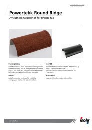
Ridge<br />
Ridge batten height with<br />
Round Ridge Big<br />
NORDIC CC<br />
50 mm<br />
H<br />
30 mm<br />
Table: Round Ridge Big<br />
Roof pitch 10º 15º 20º 25º 30º 35º 40º 45º 50º<br />
Hight in mm 155 145 140 125 115 105 90 80 60<br />
The height given is allowing a ventilation gap of 20 mm between<br />
the round ridge and the tiles, based on 30 mm height of<br />
battens both sides. NB: The ridge batten is installed at the correct<br />
heigth (H) above the ridge to support the Round Ridge (Big<br />
or Small). The heigth will vary with varying roof pitches, and<br />
with the chosen ridge element. The Ridge Ventilation Band can<br />
only be installed together with the Round Ridge Big.<br />
11
Ridge with Round Ridge Big<br />
NORDIC CC<br />
Install the ridge batten holder and ridge batten, properly aligned,<br />
at the appropriate height, then fix the Ridge Ventilation<br />
Band. Then fix the spacers for the round ridges 375 mm apart.<br />
NB: The Ridge Ventilation Band is fitted directely over the ridge<br />
batten up to a height (H) of max. 125 mm. Where the height<br />
(H) is greater, an additonal batten over the Ridge Ventilation<br />
Band is required.<br />
When the <strong>Isola</strong> Ridge Ventilation Band is not used the cut roof<br />
tiles of the top row can be bent up 20 - 30 mm as an alternative.<br />
This measurement has then to be added when cutting the<br />
tiles for the top row.<br />
Capping of the ridge can start from the left or right end of<br />
the roof. Round Ridge single module Start and End pieces are<br />
available. The Round Ridges can then be laid in an overlapping<br />
arrangement and fixed from above at the overlaps.<br />
If a full number of the 3-module Round Ridges do not match<br />
exactly to the ridge length of the roof, it should be used singlemodule<br />
Round Ridges at the last 1 - 2 m adjusting the overlaps<br />
to fit. Alternatively the last piece of Round Ridge should be cut<br />
to fit and formed at the end over the Ridge End Plate.<br />
12
Angle ridge<br />
NORDIC CC<br />
The top row of cut roof tiles to be bent up 20 - 30 mm and<br />
fixed. On both sides of the ridge a batten (max 24 mm thick)<br />
shall be placed parallell to and over the underlying battens<br />
and fixed down into the batten with appropriate nails or<br />
screws. Distance between the overlying battens to be adjusted<br />
to the width of the <strong>Powertekk</strong> Angle Ridge. Angle Ridge<br />
to be placed with ca 10 cm overlapping and fixed horisontally<br />
into the battens.<br />
Ventilation of the ridge area can be provided through the<br />
installation of Roof Vent 75, or the overlying battens can be<br />
installed in pieces of ca 50 cm with an appropirate gap between<br />
the pieces.<br />
13
Hip<br />
NORDIC CC<br />
The hip capping is identical to the ridge capping. At the eaves<br />
the hip should be closed with a Ridge/Hip end Cap. The tiles<br />
can be bent up approx. 20 mm at the sides of the hip batten<br />
as an alternative to the <strong>Isola</strong> Ridge Ventilation Band.<br />
The Round Ridges should be cut to fit where the ridge and<br />
hip meet and covered with a <strong>Powertekk</strong> Y-Ridge 10°-30° or<br />
30°-50°, or the joint should be covered with Isoflex P, which is<br />
the selfadhesive, flexible, granule covered Alu-band for joints.<br />
As an alternative the joint can be covered by lead sheet. The<br />
lead can be matched with the colour of the roof using the<br />
Reapir Kit. The surface to be coated must be free from dust,<br />
grease or oils.<br />
14
Gable with Barge Board Cover<br />
NORDIC CC<br />
25 mm<br />
A barge board is required in order to form the gable. It should<br />
be max. 24 mm thick and shall be fitted 25 mm higher than<br />
the top edge of the tile battens. Installed underlayers should<br />
be dressed up and fixed on the top of the barge board.<br />
Start installing from the eaves. Place the Barge Board Cover<br />
on the barge board and secure from the top and side. The<br />
Barge Board Covers should at the top be covered by the<br />
Round Ridge. The overlapping Round Ridge should be cut in<br />
the area of the cover and bent up to fit.<br />
NB: If the full tiles do not fit exactly to the total length of the<br />
roof the roof tiles must be cut to size accordingly and turned<br />
up approx. 20 mm against the barge board. In the eaves end<br />
the open profile of the Barge Board Cover can be closed. Just<br />
a few straight cuts and bends are required.<br />
15
Gable with Gable Tile<br />
NORDIC<br />
With this type of gable roofing, the roof width must have<br />
exact modular dimensions (see page 27 Table: Covered width<br />
of roof with Gable Tile, <strong>Powertekk</strong> Nordic).<br />
The barge board shall be mounted with the top at the same<br />
level as the top of the battens.<br />
The Gable Tiles shall be installed parallell with the installation<br />
of the roof tiles. The first Gable Tile (second row from top) to<br />
be placed and fixed temporarily with one nail vertically into<br />
the batten through the prepunched hole.<br />
As the roof tiles are being installed, the Gable Tiles should<br />
each be secured on the side and on the front where they overlap.<br />
16
Gable with Gable Tile<br />
CC<br />
For the installation of Gable Tile CC a barge board shall be<br />
fixed with the top edge to fit against the underside of the tile<br />
battens.<br />
The tile battens to be cut flush with the face of the barge<br />
board. If the tiles have to be cut to fit, allow an extra 10 – 20<br />
mm for bending up.<br />
The Gable Tile CC shall be installed one by one over the ready<br />
installed roof tiles, starting from the eaves. Each Gable Tile CC<br />
shall be fixed on the side with two nails/screws into the barge<br />
board/battens.<br />
17
Valley<br />
NORDIC CC<br />
50 mm<br />
50 mm<br />
150 mm 150 mm<br />
The valley shall be provided with two (counter)battens at each<br />
side. The valley is preformed for 30 mm high battens. These<br />
battens should be laid parallel with the bottom line of the valley<br />
and 150 mm out form the center at both sides. The tile battens<br />
end in the middle of the valley's two battens.<br />
145 mm 145 mm<br />
Fit the <strong>Powertekk</strong> Valley sections with an overlap of 80 mm<br />
and secure at the side with fixing clips.<br />
NB: The valley sections have a water channel measuring 145<br />
mm to each side and they are tapered towards one end. The<br />
narrow, marked side should be laid towards the eaves.<br />
For continuous support valley boards shall be installed at rafter<br />
level.<br />
18
80 mm<br />
The roughly cut roof tiles should overlap into the valley by<br />
minimum 80 mm from the edge of the installed steel valley.<br />
Use a chalk line to mark a straigth line in correct poisiton (80<br />
mm overlap) and cut along the line.<br />
Of optical reasons the tiles may be bent down along the cut<br />
edges.<br />
Cutting of the tiles<br />
The necessary cutting to size should be done "cold" using suitable<br />
hand shears or guillotine shears. Cutting can also be done<br />
by circular saw with a cutting blade specially for this purpose.<br />
Heat-generating cutting with rotating machines faster than<br />
4000 rpm must not be used. Overheating of the metal when<br />
cutting will damage the corrotion protection (zinc) along the<br />
cut edge.<br />
For <strong>Powertekk</strong> Nordic the following tools can be recommended:<br />
Festool TS 55 EBQ oder ATF 55 EB<br />
Panasonic EY 3530<br />
19
Chimney flashing<br />
NORDIC CC<br />
Place battens/boards above and below the chimney for support<br />
of the tiles.<br />
Adjust and cut the tiles around the chimney, add 20 - 30 mm<br />
for bending up. The chimney should be flashed with Isoflex<br />
P, then secured and sealed mechanically with a capping strip.<br />
Alternatively the covering can be made with a traditional<br />
flashing. Make sure that the flashing at the back of the chimney<br />
is built up to lead the water to the sides of the chimney.<br />
20
Sidewall flashing<br />
NORDIC CC<br />
The roof tiles should be laid right up to the wall. If a roofing<br />
tile has to be cut to non-modular size, it should be turned up<br />
approx. 20 mm against the wall. The Sidewall Flashing should<br />
be installed from the eaves towards the ridge, then secured<br />
and sealed with a capping strip.<br />
Alternatively Isoflex P can be used as replacement for the<br />
Sidewall Flashing. Shall also be fixed to the wall with a capping<br />
strip and sealed.<br />
21
Front wall flashing<br />
NORDIC CC<br />
Depending upon type of construction ventilation shall be provided<br />
integrated in the construction, or by means of installing an<br />
appropriate number of Roof Vent 75.<br />
The last batten against the wall to be replaced by a board of<br />
thickness 25 mm.<br />
Install <strong>Powertekk</strong> tiles up to the wall. The last tile to be cut and<br />
bent up 25 mm. Place a batten max 20 mm thick on top of the<br />
upper tile and fix through the tiles into the underlying board.<br />
Install the Front Wall Flashing and fix from the front into the<br />
batten and also fix in top of the vertical part on the wall. Finally<br />
install and seal the Wall Sealing Strip.<br />
22
Installation of accessories<br />
Base plate<br />
NORDIC CC<br />
The Base Plate is used as a basis for fixing of individual steps<br />
and platforms. (The bracket is of make Flender and will fit the<br />
system components from the same producer). It is fixed directly<br />
through the battens using screws. The roof tiles at both sides<br />
overlap the Base Plate. It is fixed in the front by the adjoining<br />
roof tiles. The prefitted bracket should be checked to make<br />
sure that it is firmly attached and the screws tightened if necessary.<br />
The bracket of the Base Plate is limited to roof pitches<br />
between 22° and 55°.<br />
Pipe Penetration Tile<br />
NORDIC CC<br />
For aerials and pipes up to Ø 60 mm. The roof tiles on both<br />
sides overlap the Pipe Penetration Tile. The only fixing in the<br />
front is in the adjoining roof tiles.<br />
23
Roof Vent 75<br />
NORDIC CC<br />
Roof Vent 75 is used wherever constructional ventilation is<br />
not possible. The ventilation opening is 75 cm². The roof tiles<br />
on both sides overlap the vent. The only fixing in the front is<br />
in the adjoining roof tiles.<br />
Sanitary Vent<br />
NORDIC CC<br />
The Sanitary Vent is used to ventilate/extract air from kitchens,<br />
bathrooms etc.. The ventilator is supplied with an insulated<br />
insert, and an adapter for connection to Ø 100, 110, 125,<br />
130 and 150 mm. For roof pitches 10° - 45°.<br />
The roof tiles on both sides overlap the vents. The only fixing<br />
in the front is in the adjoining roof tiles.<br />
24
Soil Pipe Vent<br />
NORDIC CC<br />
The Soil Pipe Vent is used to ventilate the domestic vaste<br />
water pipes. The vent is supplied with a flexible connection<br />
pipe, connecting to Ø 50, 75 and 100 mm.<br />
The roof tiles on both sides overlap the vents. The only fixing<br />
in the front is in the adjoining roof tiles.<br />
Skylight / roof exit<br />
NORDIC<br />
To fit a skylight, leave a “2x4-tile” opening when installing the<br />
roofing tiles. Then insert the skylight. Cut and adjust the downturn<br />
end of the overlying tile row to fit. The window should be<br />
fixed to the rafters at the sides by means of its fixing straps.<br />
25
Installation of roof windows<br />
NORDIC CC<br />
General:<br />
Any make of roofwindow for living areas can be installed in a<br />
<strong>Powertekk</strong> roof. When using prefabricated flashings, use the<br />
types for normal concrete or ceramic roof tiles (for example<br />
Velux type EDW). The deviations from the manufacturer's<br />
installation instructions only relate to the base, depending on<br />
the system.<br />
When integrating a window, it is vital that the base with its<br />
supports and supplementary timbers are generally placed<br />
directly on the rafter, i.e. the support timbers are arranged<br />
in such a way that the top edge of the support is level with<br />
the top edge of the counter-batten. The support must be no<br />
thicker than the counter-battens used. A width of approx.<br />
15 cm must be available as a support for the prefabricated<br />
flashings.<br />
The window itself shall be fitted in accordance with the<br />
manufacturer’s instructions.<br />
26
Covered width with Gable Tile<br />
NORDIC<br />
185 mm 1110 mm<br />
273 mm<br />
Covered width measured to outside face of barge board<br />
Covered width (mm)<br />
Number Additional<br />
of tiles profile waves 1 2 3 4 5<br />
Cut length 273 458 643 828 1.013<br />
1 1.568 1.753 1.938 2.123 2.308 2.493<br />
2 2.678 2.863 3.048 3.233 3.418 3.603<br />
3 3.788 3.973 4.158 4.343 4.528 4.713<br />
4 4.898 5.083 5.268 5.453 5.638 5.823<br />
5 6.008 6.193 6.378 6.563 6.748 6.933<br />
6 7.118 7.303 7.488 7.673 7.858 8.043<br />
7 8.228 8.413 8.598 8.783 8.968 9.153<br />
8 9.338 9.523 9.708 9.893 10.078 10.263<br />
9 10.448 10.633 10.818 11.003 11.188 11.373<br />
10 11.558 11.743 11.928 12.113 12.298 12.483<br />
11 12.668 12.853 13.038 13.223 13.408 13.593<br />
12 13.778 13.963 14.148 14.333 14.518 14.703<br />
13 14.888 15.073 15.258 15.443 15.628 15.813<br />
14 15.998 16.183 16.368 16.553 16.738 16.923<br />
15 17.108 17.293 17.478 17.663 17.848 18.033<br />
Covered width with Gable Tile<br />
CC<br />
1180 mm<br />
Covered width measured to outside face of barge board<br />
Covered width (mm)<br />
Number Additional<br />
of tiles profile waves 1 2 3 4 5<br />
Cut length 255 440 625 810 995<br />
1 1.180 1.365 1.550 1.735 1.920 2.105<br />
2 2.290 2.475 2.660 2.845 3.030 3.215<br />
3 3.400 3.585 3.770 3.955 4.140 4.325<br />
4 4.510 4.695 4.880 5.065 5.250 5.435<br />
5 5.620 5.805 5.990 6.175 6.360 6.545<br />
6 6.730 6.915 7.100 7.285 7.470 7.655<br />
7 7.840 8.025 8.210 8.395 8.580 8.765<br />
8 8.950 9.135 9.320 9.505 9.690 9.875<br />
9 10.060 10.245 10.430 10.615 10.800 10.985<br />
10 11.170 11.355 11.540 11.725 11.910 12.095<br />
11 12.280 12.465 12.650 12.835 13.020 13.205<br />
12 13.390 13.575 13.760 13.945 14.130 14.315<br />
13 14.500 14.685 14.870 15.055 15.240 15.425<br />
14 15.610 15.795 15.980 16.165 16.350 16.535<br />
15 16.720 16.905 17.090 17.275 17.460 17.645<br />
27
Covered width with<br />
Barge Board Cover<br />
NORDIC<br />
Covered width measured to the inside face of barge board<br />
Covered width (mm)<br />
Number Additional<br />
of tiles profile waves 1 2 3 4 5<br />
Cut length 273 458 643 828 1.013<br />
1 1.198 1.383 1.568 1.753 1.938 2.123<br />
2 2.308 2.493 2.678 2.863 3.048 3.233<br />
3 3.418 3.603 3.788 3.973 4.158 4.343<br />
4 4.528 4.713 4.898 5.083 5.268 5.453<br />
5 5.638 5.823 6.008 6.193 6.378 6.563<br />
6 6.748 6.933 7.118 7.303 7.488 7.673<br />
7 7.858 8.043 8.228 8.413 8.598 8.783<br />
8 8.968 9.153 9.338 9.523 9.708 9.893<br />
9 10.078 10.263 10.448 10.633 10.818 11.003<br />
10 11.188 11.373 11.558 11.743 11.928 12.113<br />
11 12.298 12.483 12.668 12.853 13.038 13.223<br />
12 13.408 13.593 13.778 13.963 14.148 14.333<br />
13 14.518 14.703 14.888 15.073 15.258 15.443<br />
14 15.628 15.813 15.998 16.183 16.368 16.553<br />
15 16.738 16.923 17.108 17.293 17.478 17.663<br />
28
Covered length of roof<br />
from eaves to ridge<br />
NORDIC CC<br />
Number Covered length in mm<br />
of tiles NORDIC CC<br />
1 389 391<br />
2 758 762<br />
3 1.127 1.133<br />
4 1.496 1.504<br />
5 1.865 1.875<br />
6 2.234 2.246<br />
7 2.603 2.617<br />
8 2.972 2.988<br />
9 3.341 3.359<br />
10 3.710 3.730<br />
11 4.079 4.101<br />
12 4.448 4.472<br />
13 4.817 4.843<br />
14 5.186 5.214<br />
15 5.555 5.585<br />
16 5.924 5.956<br />
17 6.293 6.327<br />
18 6.662 6.698<br />
19 7.031 7.069<br />
20 7.400 7.440<br />
21 7.769 7.811<br />
22 8.138 8.182<br />
23 8.507 8.553<br />
24 8.876 8.924<br />
25 9.245 9.295<br />
26 9.614 9.666<br />
27 9.983 10.037<br />
28 10.352 10.408<br />
29 10.721 10.779<br />
30 11.090 11.150<br />
NB: The covered length is measured from the rafter end up to<br />
the front side of the top batten.<br />
29
Needs for <strong>Powertekk</strong><br />
<strong>Powertekk</strong>- Application<br />
Product<br />
Roof area Tiles General roof cover<br />
Ridge / Hip Round Ridge 1) Ridge / Hip<br />
Round Ridge 3-modules 2) Ridge / Hip<br />
Round Ridge End Plate End cover for Round Ridge<br />
Round Ridge Start Start of ridge cover<br />
Round Ridge End End of ridge cover<br />
Hip End Cap Big<br />
Hip End at eaves<br />
Hip End Cap Small Hip End at eaves<br />
Y-Ridge 10˚ - 30˚<br />
Hip / Ridge connection<br />
Y-Ridge 30˚ - 50˚<br />
Hip / Ridge connection<br />
Ridge Ventlation Band 3) Ridge / Hip<br />
Angle Ridge<br />
Ridge / Hip<br />
Eaves Eaves Flashing Eaves<br />
Gable end Barge Board Cover, Gable<br />
right / left<br />
Gable Tile Nordic, Gable<br />
right / left<br />
Gable Tile CC,<br />
Gable<br />
right / left<br />
Wall flashings Side Wall Flashing Upstanding wall parallel<br />
right / left<br />
to the gable<br />
Front Wall Flashing<br />
Upstanding wall parallel to eave/ridge<br />
Valley Valley Valley<br />
Fixings Nails / Screws For Fixing of <strong>Powertekk</strong><br />
Other Wall Sealing Strip For sealing at vertical surfaces<br />
accessories Flat Sheet Covering of flat surfaces<br />
Pipe Penatration Tile for aerials<br />
Soil pipe Vent<br />
for ventilation of vaste water system<br />
Sanitary Vent<br />
ventilation from bathrooms, kitchens<br />
Univent 200<br />
Multipurpose ventilator CC<br />
Roof Vent 75<br />
Roof Ventilation<br />
Base Plate<br />
Support for roof steps<br />
Transparent Tile 2-modules for Nordic<br />
Transparent Tile 3-modules for CC<br />
Skylight<br />
Exit for roof services<br />
Isoflex P<br />
for details, selfadhesive<br />
Repair Kit<br />
Repair of small surface damages<br />
1) Round Ridge is available in Big: Ø 215 mm and Small Ø 150 mm<br />
2) Round Ridge 3-modules is available in granuled version only<br />
3) Ridge Ventilation Band ist suitable for installation with Round Ridge Big only<br />
30
NORDIC CC<br />
Effective length/<br />
area<br />
Material required<br />
1.110 mm x 369 mm 2,44 tiles / m 2<br />
380 mm 2,63 pcs / m<br />
1.130 mm 0,88 pcs / m<br />
–––––––– 1,00 pcs / detail<br />
380 mm 1,00 pcs / detail<br />
380 mm 1,00 pcs / detail<br />
200 mm 1,00 pcs / detail<br />
200 mm 1,00 pcs / detail<br />
–––––––– 1,00 pcs / detail<br />
–––––––– 1,00 pcs / detail<br />
5.000 mm 0,20 pcs / m<br />
1.150 mm 0,87 pcs / m<br />
1.200 mm 0,83 pcs / m<br />
1.110 mm 0,90 pcs / m<br />
185 mm 2,71 pcs / m<br />
2,71 pcs / m<br />
1.110 mm 0,90 pcs / m<br />
1.150 mm 0,87 pcs / m<br />
1.150 mm 0,87 pcs / m<br />
10 pcs / m 2<br />
1200 mm 0,83 pcs / m<br />
1250 mm x 450 mm<br />
369 mm x 370 mm 1,00 pcs / detail<br />
369 mm x 370 mm 1,00 pcs / detail<br />
369 mm x 370 mm 1,00 pcs / detail<br />
369 mm x 370 mm 1,00 pcs / detail<br />
369 mm x 370 mm 1,00 pcs / detail<br />
369 mm x 185 mm 1,00 pcs / detail<br />
370 x 369 mm 1,00 pcs / detail<br />
555 x 369 mm 1,00 pcs / detail<br />
738 mm x 738 mm 1,00 pcs / detail<br />
1.250 mm x 300 mm<br />
31
Snow guard fence<br />
NORDIC CC<br />
1. Install the <strong>Powertekk</strong> tiles as described. At the level where<br />
the snow fence shall be installed leave one row of tiles open.<br />
2. Fix a board (width 80 – 100 mm) above the tile batten. The<br />
board shall be approx. 10 mm thinner than the the batten.<br />
Push the snow guard bracket tight against the upper part of<br />
the tile. Then fix the bracket with two screws (6,5 x 38 mm)<br />
into the already installed board.<br />
3. Close the open row of tiles.<br />
32
4. Insert the metal clip in the slot at the top of the bracket and<br />
leave it open. Place the snowfence into the brackets at the<br />
desired level and close by turning the clip over and pressing the<br />
tab into the hole till it clicks tight.<br />
Joining of fences is done simply by pushing the male/female<br />
joints together.<br />
33
Holders for round timber<br />
NORDIC CC<br />
1. Install the <strong>Powertekk</strong> tiles as described. At the level where<br />
the snow fence shall be installed leave one row of tiles open.<br />
2. Fix a board (width 80 – 100 mm) above the tile batten. The<br />
board shall be approx. 10 mm thinner than the the batten.<br />
Push the bracket tight against the upper part of the tile. Then<br />
fix the bracket with two screws (6,5 x 38 mm) into the already<br />
installed board.<br />
3. Close the open row of tiles.<br />
34
Single steps<br />
For mounting parallell with<br />
the installation of <strong>Powertekk</strong> tiles<br />
NORDIC CC<br />
Normally a number of Single Steps are installed in a continous<br />
vertical line and interconnected. The step at the top shall always<br />
be secured to the roof structure by means of a fixing rail that is<br />
fixed with screws into the rafters. In the case of installing one or<br />
more single steps in more than one vertical line, the upper step<br />
for each vertical line shall always be fixed to a fixing rail. One<br />
step corresponds to the height of one row of <strong>Powertekk</strong> tiles.<br />
1. Install the <strong>Powertekk</strong> tiles as described. At the level where<br />
the fixing rail shall be installed leave one row in apropriate<br />
width of tiles open.<br />
2. Place the fixing rail above the tile batten and locate the<br />
underlying rafters. Enter the two holders sideways into the<br />
fixing rail. Enter the two U-formed pieces into the holders and<br />
finally enter the top step into the last pieces and press down<br />
until it clicks in place. Now push the fixing rail with the mounted<br />
step upwards till its tight against the upper vertical part of<br />
the <strong>Powertekk</strong> tile.<br />
35
3. Secure the fixing rail with the supplied screws. Screw shall<br />
be located in the center of the rafter and shall go minimum 30<br />
mm into the rafter. Close the open row of tiles above the fixing<br />
rail.<br />
4. Lift the tile with the mounted step just enough to enter the<br />
next step under the tile, hanging it over the batten. Connect<br />
the two steps by entering the upstanding hook into the keyhole<br />
slot and pull tight.<br />
5. Continue the following steps in the same way parallell with<br />
installing the tiles.<br />
36
Roof ladder<br />
Roof ladder for installation<br />
after the <strong>Powertekk</strong> installation.<br />
NORDIC CC<br />
1. Install the <strong>Powertekk</strong> tiles as described. At the level where<br />
the fixing rail shall be installed leave one row in apropriate<br />
width of tiles open.<br />
2. Assemble the 3-step ladder with a distance between the<br />
vertical rails of 37 cm. Fix the two brackets to the vertical sides<br />
of the ladder. Place the fixing rail above the tile batten and<br />
locate the undelying rafters.<br />
Fix the stop plates to the brackets and hook into the fixing rail<br />
and lock in position. Now push the fixing rail with the mounted<br />
brackets upwards till its tight agains the upper vertical part of<br />
the <strong>Powertekk</strong> tile.<br />
Secure the fixing rail to the rafters with the supplied screws.<br />
Screws shall be located in the center of the rafter and shall go<br />
minimum 30 mm into the rafter.<br />
Position the brackets sideways so that the vertical parts of<br />
the ladder are located in the bottom of the profiles of the<br />
<strong>Powertekk</strong> tiles.<br />
37
3. Close the open row of tiles above the fixing rail. Further ladder<br />
elements in direction of the eaves can now be installed. The<br />
parts are joined on the sides with the supplied joining flat bar and<br />
screws.<br />
4. At the eaves end the ladder shall be secured with brackets. Lift<br />
the <strong>Powertekk</strong> tile and hang the hooks of the flat bars over the<br />
underlying battens, press the tiles down and fix as normal. Attach<br />
the ladder to the two vertical parts of the brackets with the supplied<br />
screws.<br />
38
Chimney Platform<br />
NORDIC CC<br />
1. Install the <strong>Powertekk</strong> tiles as described. At the level where<br />
the fixing rail shall be installed leave one row in apropriate<br />
width of tiles open.<br />
2. Place the fixing rail above the tile batten and locate the<br />
undelying rafters. Fix the stop plates to the brackets and hook<br />
into the fixing rail and lock in position. Now push the fixing<br />
rail with the mounted brackets upwards till its tight agains the<br />
upper vertical part of the <strong>Powertekk</strong> tile.<br />
Secure the fixing rail to the rafters with the supplied screws<br />
6,5 x 64 mm. Screws shall be located in the center of the rafter<br />
and shall go minimum 30 mm into the rafter. Position the<br />
brackets sideways so that they are localted in the bottom of<br />
the profiles of the <strong>Powertekk</strong> tiles. Finally tighten the screws<br />
(8 x 20 mm) of the two stop plates in the fixing rail.<br />
39
3. Place and fix the <strong>Powertekk</strong> tiles in the open row of tiles<br />
over the fixing rail.<br />
4. Screw the platform brackets to the fixing brackets with<br />
2 pcs 8 x 20 mm bolts and nuts, fix the platform to these<br />
brackets with 2 pcs 6 x 16 mm bolts and washer head nuts.<br />
Adjust the platform to horisontal position.<br />
NB! The support brackets of the platform must not lay on the<br />
flashing around the chimney. The free end of the platform<br />
must not protrude more than 25 cm outside the supporting<br />
brackets.<br />
6 x 16 mm<br />
6,5 x 64 mm<br />
8 x 20 mm<br />
40
Safety Hooks<br />
NORDIC CC<br />
1. Install the <strong>Powertekk</strong> tiles as described. At the level where<br />
the fixing rail shall be installed leave one row in apropriate<br />
width of tiles open.<br />
2. Place the fixing rail above the tile batten and locate the<br />
underlying rafters. Fix the holding brackets onto the safety<br />
hook and slide this sideways onto the fixing rail. Now push the<br />
fixing rail with the mounted safety hook upwards till its tight<br />
agains the upper vertical part of the <strong>Powertekk</strong> tile.<br />
3. Secure the fixing rail to the rafters with the supplied screws<br />
6,5 x 64 mm. Screws shall be located in the center of the rafter<br />
and shall go minimum 30 mm into the rafter. Close the open<br />
row of tiles over the fixing rail.<br />
41
Solar panel support system<br />
NORDIC CC<br />
The solar panel support system is a system providing vertical<br />
support rails above the <strong>Powertekk</strong> roof covering. The rails will<br />
serve as a base for the manufacturer specific systems for support<br />
of solar panels on pitch roofs.<br />
1. Install the <strong>Powertekk</strong> tiles as described. At the level where<br />
the fixing rail shall be installed leave one row in apropriate<br />
width of tiles open.<br />
2. Place the fixing rail above the tile batten and locate the<br />
undelying rafters. Enter the two holders sideways into the<br />
fixing rail. Enter the two U-formed pieces into the holders and<br />
finally enter the holding brackets into the last pieces and press<br />
down until it clicks in place. Now push the fixing rail with the<br />
mounted step upwards till its tight agains the upper vertical<br />
part of the <strong>Powertekk</strong> tile.<br />
42
3. Secure the fixing rail to the rafters with the supplied screws<br />
6,5 x 64 mm. Screws shall be located in the center of the rafter<br />
and shall go minimum 30 mm into the rafter. The fixing rails<br />
can be extended sidewise with sections of 1.25 m to the required<br />
width of the solar panel system in question.<br />
Close the open row of tiles over the fixing rail(s).<br />
4. Further support brackets in direction of the eaves shall be<br />
installed at every third row of tiles. Lift the <strong>Powertekk</strong> tile and<br />
hang the hooks of the flat bars over the underlying battens,<br />
press the tiles down and fix as normal.<br />
5. The L-rails are then fixed to the brackets with the 8 x 20 mm<br />
bolts and nuts. The L-rail are extended using the supplied bolts<br />
and nuts, placing the joining piece on the inside of the vertical<br />
part of the L-rail.<br />
43
Technical data<br />
NORDIC<br />
CC<br />
Area of application<br />
New buildings and renovation<br />
of old roofs<br />
Roof gradient: 10º - 90º<br />
Batten spacing: 369 mm 371 mm<br />
Plate size: 1198 x418 mm 1180 x411 mm<br />
Covered area: 1110 x369 mm 1110 x371 mm<br />
Panels per m²:<br />
2,44 pcs<br />
Steel thickness: 0,50 mm 0,45 mm<br />
Galvanizing (zinc coating): 275 g/m 2<br />
Weigth: 3,1 kg / tile 2,05 kg / tile<br />
7,7 kg / m 2 5,0 kg / m 2<br />
Surface texture: coloured Polyurethane<br />
granules coating<br />
covered with<br />
clear acrylic<br />
08.2007<br />
NORWEGIAN<br />
ACCREDITATION<br />
No S03<br />
NS- ISO 9001 CERTIFICATED FIRM<br />
<strong>Isola</strong> as<br />
N-3945 ˇ Porsgrunn<br />
Tel.: +47 35 57 57 00<br />
Fax: +47 35 55 48 44<br />
www.isola.com<br />
Dry and healthy buildings