Girard Awnings R
Girard Awnings R
Girard Awnings R

You also want an ePaper? Increase the reach of your titles
YUMPU automatically turns print PDFs into web optimized ePapers that Google loves.
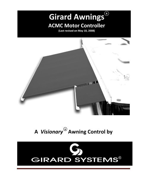
<strong>Girard</strong> <strong>Awnings</strong> R<br />
ACMC Motor Controller<br />
(Last revised on May 10, 2008)<br />
R<br />
A Visionary Awning Control by
<strong>Girard</strong> AC Motor Controller Installation Guide<br />
ACMC<br />
Revision 2.08<br />
May 10, July 2008<br />
ACMC Installation Guide Rev 2.08 1
Instructions for Safe Operation<br />
1. RANGE OF ENVIRONMENT CONDITIONS<br />
This product is designed to be safe under the following environmental conditions:<br />
Indoor Use<br />
Altitude up to 2000M<br />
Temperature of 5°C to 40°C<br />
Maximum relative humidity 80%<br />
Mains supply voltage fluctuations not to exceed ± 10 % of the nominal<br />
Voltage.<br />
2.<br />
This symbol is marked on the equipment when it is necessary for<br />
the user to refer to the manual for important safety information.<br />
3.<br />
This symbol denotes a potential hazard. Attention must be given to<br />
the statement to prevent damage, destruction or harm.<br />
ACMC Installation Guide Rev 2.08 2
Table of Contents<br />
1 Introduction .................................................................................................................................... 4<br />
2 Installing the ACMC ..................................................................................................................... 5<br />
2.1 Mounting ................................................................................................................................ 5<br />
2.2 General Wiring Considerations .......................................................................................... 6<br />
2.2.1 Warning! ............................................................................................................................ 6<br />
2.2.2 Power Supply .................................................................................................................... 6<br />
2.2.3 High Voltage Connections .............................................................................................. 6<br />
2.2.4 Low Voltage Connections .............................................................................................. 7<br />
2.2.5 RF Antenna ....................................................................................................................... 7<br />
2.3 Grounding .............................................................................................................................. 7<br />
3 High Voltage Connections ........................................................................................................... 8<br />
3.1 AC Motor Output (PL200) ................................................................................................. 8<br />
3.2 ACS control input (PL201) ................................................................................................. 8<br />
3.2.1 HV Extend ........................................................................................................................ 8<br />
3.2.2 HV Retract ........................................................................................................................ 8<br />
3.3 Mains Power (PL202)........................................................................................................... 8<br />
4 Low Voltage Connections ............................................................................................................ 9<br />
4.1 Anemometer Input ............................................................................................................... 9<br />
4.1.1 Wind speed switch settings ............................................................................................. 9<br />
4.2 Retract, Extend and Stop Buttons ................................................................................... 10<br />
4.3 Retract Limit Switch ........................................................................................................... 10<br />
4.4 Connect Button ................................................................................................................... 10<br />
4.5 Status LED .......................................................................................................................... 10<br />
4.6 Low Voltage Extend Input ................................................................................................ 10<br />
4.7 Parking Brake Input ........................................................................................................... 11<br />
4.8 Ignition Input / Low Voltage Retract Input .................................................................. 11<br />
5 Customizing rf Remote to ACMC ............................................................................................ 12<br />
5.1 Learning Mode (Programming) ........................................................................................ 12<br />
5.2 Motor Calibration Process ................................................................................................. 12<br />
5.3 Normal Operation .............................................................................................................. 13<br />
5.4 Quick Reference .................................................................................................................. 13<br />
5.4.1 Programming .................................................................................................................. 13<br />
5.4.2 Calibration ....................................................................................................................... 13<br />
5.4.3 Erase all ............................................................................................................................ 13<br />
ACMC Installation Guide Rev 2.08 3
1 Introduction<br />
The ACMC (AC Motor Controller) provides multi-function control of motorized lateral<br />
arm awnings. It features redundant closure sensing and safety interlocks to prevent<br />
operation when the vehicle is in motion or in an unusable condition. The companion rf<br />
Remote Control allows the user to operate the awning from outside the coach.<br />
This document contains instructions for the proper installation and operation of the<br />
ACMC. The ACMC can be controlled by the rf Remote Control, an existing ACS<br />
Controller or from a wall switch. In addition to basic extend and retract functionality, the<br />
ACMC supports the following features (not all features are fitted to all models, please refer<br />
to the model number for specific features):<br />
• Ignition monitoring When the vehicle ignition is turned on, the awning is<br />
automatically retracted for safety reasons.<br />
• Parking-brake monitoring When the vehicle parking brake is released, the<br />
awning is automatically retracted.<br />
• Anemometer (Wind-speed) sensing An external anemometer, supplied by <strong>Girard</strong>,<br />
may be used to measure local wind-speed. The awning will be automatically<br />
retracted when the wind-speed exceeds a preset, user selectable threshold.<br />
• Limit-switch inputs The motor is automatically stopped when the awning position<br />
limit-switch is tripped.<br />
• Current-limiter The motor is automatically stopped when it stalls at the extent of<br />
operation (box closed condition). The current-limiter is implemented on retract<br />
only, in order to account for awning-stretch over time, ensuring that the awning is<br />
fully retracted.<br />
The RF communication protocol is proprietary, and uses the ISM licence-free band for RF<br />
communication (316.05MHz). The ACMC can be configured for use with a maximum of<br />
16 rf remote controls (more than one channel from a single remote is permitted, if for<br />
example, group and individual control is required). The ACMC requires 120V ac power<br />
from either shore input or an inverter input.<br />
The ACMC hardware is available in a number of different configurations, set at the<br />
factory. In all configurations the primary function of the board is to control a reversible AC<br />
motor.<br />
Version 1 (serial number suffix ver1) has a built in current limiter, rf communication,<br />
anemometer inputs, low voltage awning control capability and a limit switch input for<br />
retract operation. (This version will replace the earlier SOMFY-ACL controllers.)<br />
Version 2 (serial number suffix ver2) has a built in current limiter, rf communication,<br />
anemometer inputs, low voltage awning control capability, a limit switch input for retract<br />
operation and safety interlocks for park brake and ignition inputs.<br />
Version 3 (serial number suffix ver3) has a built in current limiter, rf communication,<br />
anemometer inputs, low voltage awning control capability, a limit switch input for retract<br />
operation, safety interlocks for park brake and ignition inputs and an interface to an<br />
existing ACS controller panel.<br />
ACMC Installation Guide Rev 2.08 4
2 Installing the ACMC<br />
2.1 Mounting<br />
1. Determine suitable mounting location for the ACMC board. The back wall of a<br />
cabinet is ideal, as it provides a solid mounting surface.<br />
2. Use the mounting holes on the corners of the plastic casing and wood screws to<br />
mount the device.<br />
3. Wire the awnings and power using the connectors mounted on the Printed<br />
circuit board making sure it is the direction indicated on the board.<br />
4. Connect the outputs to other devices, passing the wire through the provided<br />
strain relief.<br />
5. Motor ground must be connected to maintain electrical safety.<br />
6. Tighten the strain relief on both sides of the device before screwing the top on.<br />
ACMC Installation Guide Rev 2.08 5
2.2 General Wiring Considerations<br />
2.2.1 Warning!<br />
Use extreme caution when making the power connections to the AC<br />
mains. Power must be turned OFF before any connections are made.<br />
Under no circumstances should the wiring be done when the<br />
electrical components are energized. The ACMC unit is to be<br />
installed by a qualified electrician in accordance with national and<br />
local electrical codes and the instructions in this document.<br />
2.2.2 Power Supply<br />
This device is designed to operate on 115V AC at 60HZ. The necessary power-rating will<br />
be determined by the specifications for motor being used.<br />
2.2.3 High Voltage Connections<br />
The high-voltage connections are described in detail in section 3. Wire all high-voltage<br />
connections using the appropriate mating halves for the connectors mounted on the board.<br />
Take note of the labels marked on the board, and ensure that all wires are connected as<br />
indicated.<br />
IMPORTANT: The following guidelines should be adhered to for high-voltage wiring:<br />
1. The ends of the wire must be stripped neatly to about 1/3 rd of an inch and if<br />
possible tinned to prevent fraying.<br />
2. Extra care must be taken to ensure the connections are made in accordance with the<br />
wiring diagram presented in section 3.<br />
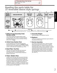
3. If the wire has stranded conductors, make sure that there are no loose strands<br />
outside the terminal contact.<br />
WRONG (Notice the<br />
loose strands outside<br />
the terminal contact)<br />
4. Be sure to pass the wires through the provided strain relief. Tighten the strain relief<br />
on both sides before attaching the top of the enclosure.<br />
5. DO NOT TOUCH any part of the board at any time when it is energized.<br />
Note: Motor ground must be connected to maintain electrical safety.<br />
If the device does not operate as expected, verify that all wires are securely and correctly<br />
connected. If it still does not work, shut off power, disconnect the wiring and call <strong>Girard</strong>.<br />
DO NOT attempt to debug the device under any circumstances. There are no user<br />
serviceable parts on this unit.<br />
ACMC Installation Guide Rev 2.08 6
2.2.4 Low Voltage Connections<br />
The low-voltage connections are described in detail in section 4. The low voltage control<br />
inputs should be connected to the appropriate mating halves for the connectors mounted to<br />
the ACMC board. As with the high-voltage connections, the provided strain relief should<br />
be utilised. The two rightmost strain-relief’s, one on either side of the box, are suggested<br />
for the low-voltage connections.<br />
2.2.5 RF Antenna<br />
On those ACMC boards with RF Communication capabilities, an RF antenna wire extends<br />
from the lower right corner of the board. This wire should pass through the drilled hole<br />
relief and out of the enclosure. It is important that this wire not be shortened (standard<br />
length is 9.5 inches), coiled or folded in any way. The antenna wire should be well<br />
separated from other wires, and kept clear of surrounding metallic objects.<br />
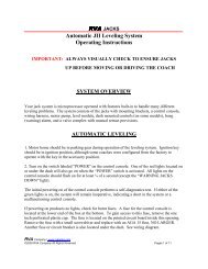
2.3 Grounding<br />
The high voltage ground is electrically isolated from the low voltage ground on the ACMC<br />
board as indicated by the figure below.<br />
+12V Low Voltage<br />
High Voltage<br />
AC 115V<br />
Battery Ground<br />
Green Wire<br />
ACMC Installation Guide Rev 2.08 7
3 High Voltage Connections<br />
3.1 AC Motor Output (PL200)<br />
The AC Motor should be wired to the AC Motor Output connector using the wire colors<br />
indicated on the ACMC board. The color convention for the selected motor should be<br />
confirmed by comparison with the diagram above, and connections made accordingly.<br />
<strong>Girard</strong> recommends AWG16/18 wire for all high voltage connections. The motor output<br />
connections indicated above are for a Left hand motor. For a Right hand motor, reverse<br />
the Retract and Extend leads – Black should now be connected to Extend and Red to<br />
Retract.<br />
3.2 ACS control input (PL201)<br />
3.2.1 HV Extend<br />
This input is functionally identical to the low-voltage extend signal (see section 4) except<br />
that it should be driven with an AC signal between 115 and 230V.<br />
3.2.2 HV Retract<br />
This input is functionally identical to the low-voltage retract signal (see section 4) except<br />
that it should be driven with an AC signal between 115 and 230V.<br />
3.3 Mains Power (PL202)<br />
The ACMC is designed to operate on 115V AC at 60HZ. The ACMC will work with both<br />
shore power and inverter power. The necessary power rating will be determined by the<br />
specifications for motor being used. DO NOT attempt to change the specified operating<br />
voltage of the board! Note that neutral is common to both the mains and the high voltage<br />
ACS signals.<br />
ACMC Installation Guide Rev 2.08 8
4 Low Voltage Connections<br />
Note that most signals have a companion ground connection, which is assumed to be<br />
chassis ground (battery minus). In case any particular input is not used, it may be left<br />
unconnected unless specifically noted below. <strong>Girard</strong> recommends AWG20-22 wire for all<br />
low voltage connections.<br />
4.1 Anemometer Input<br />
[Pins 4 & 5 on PL403]<br />
To enable wind speed monitoring and emergency retract function, a two-wire anemometer<br />
must be connected between this input and ground. This input enables the ACMC to<br />
measure wind speed and take the appropriate action as described below.<br />
4.1.1 Wind speed switch settings<br />
The ACMC measures the wind speed using the two-wire anemometer, and if this exceeds<br />
the preset threshold for 10 seconds, the ACMC goes into an override retract state. When<br />
the wind speed falls below the threshold for one minute, the ACMC comes out of the<br />
override state. In the override state, the ACMC will not accept any commands from the rf<br />
Remote. The wind speed threshold is set using the dipswitches situated on the lower right<br />
corner of the ACMC, as described below.<br />
Switch 2 Switch 1 Wind Speed Threshold<br />
OFF OFF 18 mph (Recommended)<br />
OFF ON 20 mph<br />
ON OFF 22 mph<br />
ON ON 26 mph<br />
ACMC Installation Guide Rev 2.08 9
4.2 Retract, Extend and Stop Buttons<br />
[Pins 7, 8 & 9 (signal) and 6 (ground) on PL403]<br />
These inputs can be used as an alternative to, or instead of the rf Remote Control. External<br />
normally open switches should be connected between these inputs and ground. Three<br />
separate inputs are available for extend, retract and stop operation. It should be noted<br />
however, that an rf Remote is necessary for calibration and proper operation of the current<br />
limiter function.<br />
4.3 Retract Limit Switch<br />
[Pin 10 (signal) and Pin 2 (Ground) on PL403]<br />
This switch automatically stops a retract operation, and all subsequent retract requests at<br />
the limit of operation (closed box condition) to prevent motor stalling. This input is<br />
activated when connected to ground.<br />
4.4 Connect Button<br />
[Pin 2 (signal) and Pin 1 (Ground) on PL404]<br />
This button is used to establish an RF communication link between the ACMC and the<br />
ACS Remote Control. It is also used to initiate the motor calibration process. The Connect<br />
button can be extended to an external location using the connect button input, and a<br />
normally open push-button connected to ground.<br />
4.5 Status LED<br />
[Pin 4 (signal) and Pin 3 (Ground) on PL404]<br />
The Status LED is used during the ID/channel learning process. The status LED may also<br />
be placed externally using the external status LED output. This output is powered from 3V<br />
and includes a 220-ohm series resistance. This output may also be used with other devices<br />
(e.g., a buzzer); please contact <strong>Girard</strong> for further details.<br />
4.6 Low Voltage Extend Input<br />
[Pin 6 (signal) and Pin 5 (ground) on PL404]<br />
A switch to +12V can be used to control this input. This input is asserted when a voltage<br />
between 5 and 12V DC is applied. . The ACMC will extend the awning as long as a +12V<br />
signal is available on this input, to the limits of operation as determined by the extend limit<br />
switch.<br />
ACMC Installation Guide Rev 2.08 10
4.7 Parking Brake Input<br />
[Pin 8 (signal) and Pin 7 (Ground) on PL404]<br />
This input should be connected to the vehicle’s parking brake. The parking brake input<br />
over-rides all other inputs. For normal operation this input must be externally grounded.<br />
When the ACMC detects the parking brake is ungrounded (disengaged), it performs a full<br />
retract operation. The ACMC will also ignore all remote commands while the parking<br />
brake input is ungrounded. In the case where this input is not used, it must be connected to<br />
ground to enable normal operation of the ACMC.<br />
4.8 Ignition Input / Low Voltage Retract Input<br />
[Pin 10 (signal) and Pin 9 (Ground) on PL404]<br />
This input should be connected to the vehicle’s Ignition circuit, or to an external switch to<br />
+12V. The ACMC will retract the awning and ignore all remote commands while this<br />
input is asserted. If the input is connected to both the vehicle ignition and to the external<br />
switch, both of these should be connected through a separate diode. Please refer to the<br />
wiring diagram for details. The ACMC will retract the awning as long as a +12V signal is<br />
available on this input, to the limits of operation as determined by the retract limit switch<br />
and the current limiter function. In case of +24V Ignition circuitry, please contact <strong>Girard</strong><br />
for additional information on wiring.<br />
ACMC Installation Guide Rev 2.08 11
5 Customizing rf Remote to ACMC<br />
There are three different modes of operation of the ACMC with the rf Remote Control.<br />
They are described in the section below.<br />
5.1 Learning Mode (Programming)<br />
Before an ACMC can accept commands from an rf Remote Control, it must first ‘learn’ the<br />
ID and current channel number of the transmitting remote. The ACMC can store up to 16<br />
remote control ID/channel pairs in its memory. This means that the ACMC board can be<br />
controlled by up to 16 different rf Remote Controls and channels. One may configure the<br />
ACMC to respond to multiple channels from an rf Remote Control. This allows the ACMC<br />
to be controlled on a channel individually, and additionally be controlled as part of a<br />
group, using the same rf Remote Control. Configuring more than 16 ID/channel pairs will<br />
replace the oldest stored one and so forth.<br />
The remote ID/channel learning process can be initiated by pressing the Connect Button.<br />
When the Connect Button is pressed, the ACMC listens for a connect signal from the rf<br />
Remote Control for 20 seconds. A remote channel connect signal can be generated by<br />
simultaneously pressing extend and retract buttons on the rf Remote Control. The status<br />
LED blinks to indicate it is in ‘listen’ mode. When the connect signal is received, the<br />
ACMC stores the ID and current channel number of the transmitting remote. The status<br />
LED will turn off when programming the ID/channel is done successfully. Failure will<br />
cause the LED to stop flashing and remain on for 1 minute. This process is referred to as<br />
programming the ACMC.<br />
An existing ID/channel pair may be removed from memory by repeating the programming<br />
process as described above for the particular ID/channel pair. All stored ID/channel pairs<br />
may be removed from the ACMC’s memory by pressing and holding the Connect Button<br />
down for 10 seconds.<br />
Consult the documentation for the rf Remote Control for details on its operation.<br />
5.2 Motor Calibration Process<br />
Once an ACMC has been programmed to communicate with a particular remote, motor<br />
calibration needs to be performed. The calibration process measures the motor’s normal<br />
and stall characteristics and stores them in memory. These measurements are used by the<br />
current limiter to stop the motor when it reaches the stall condition during retract<br />
operation. The calibration operation can be performed only after an ACMC has been<br />
programmed, as it requires an rf Remote Control.<br />
The motor calibration process can be initiated by pressing the Connect Button provided on<br />
the ACMC. When the Connect Button is pressed, the ACMC listens for a motor calibrate<br />
signal from the rf Remote Control for 20 seconds. The LED will blink for the duration of<br />
the calibration process. When the motor calibrate signal is received, the ACMC will<br />
initiate calibration process. Calibration takes a total of 20 seconds after activation. The<br />
awning is first extended for five seconds and the current is measured. The awning is then<br />
retracted for ten seconds and both the run current and the stall current are measured. If the<br />
calibration process is successfully completed the LED will turn off, else it will remain on<br />
for a minute after calibration. The LED will blink at a low rate until calibration is<br />
performed properly. Calibration is a required step for proper operation of the ACMC, and<br />
only needs to be done when the awning is first installed. Care should be taken to make sure<br />
ACMC Installation Guide Rev 2.08 12
the awning is completely closed (fully retracted) before the start of the calibration; a false<br />
calibration would result in premature tripping of the awning motor.<br />
5.3 Normal Operation<br />
Normal operation can be started once the ACMC has been paired with a remote and has<br />
been calibrated. The extend, stop and retract buttons can now be used to position the<br />
awning as required. The interlocks will override user input to prevent any unsafe<br />
environmental condition from damaging the awning. All previously programmed remotes<br />
can be erased from ACMC’s memory by pressing and holding the connect button for ten<br />
seconds. The Status LED stops blinking when this process is successfully completed.<br />
5.4 Quick Reference<br />
5.4.1 Programming<br />
Push Connect button on ACMC, press and hold extend and retract buttons<br />
simultaneously on the remote control for seven seconds.<br />
5.4.2 Calibration<br />
Push Connect button on ACMC, press and hold extend and stop buttons<br />
simultaneously on the remote control for seven seconds.<br />
5.4.3 Erase all<br />
Push and hold Connect button on ACMC for ten seconds.<br />
ACMC Installation Guide Rev 2.08 13
ACMC Installation Guide Rev 2.08 14